

8J - 2 TURN SIGNALS AND HAZARD WARNING FLASHER |
|
Ä |
|
TESTING PROCEDURES
MULTI-FUNCTION SWITCH TESTS AA, AC, AP, AND AY BODIES
The multi-function switch contains electrical circuitry for turn signal, cornering lamps (optional), hazard warning, headlamp beam select, headlamp optical horn, windshield wiper, pulse wipe, and windshield washer switching. This integrated switch assembly is mounted to the left hand side of the steering column. Should any function of the switch fail, the entire switch assembly must be replaced. Refer to Fig. 1 for diagnosis.
To test the switch, first disconnect the negative battery cable, then remove the upper and lower column covers to gain access to the switch connector. Remove switch connector. Using an ohmmeter, test for continuity (no resistance) between the terminals of the switch as shown in the following continuity charts (Fig 2 or 3).
DUAL-FUNCTION SWITCH TESTSÐAG AND AJ BODIES
The dual-function switch contains electrical circuitry for hazard warning switching, and circuitry and electronics for turn signal cancellation. The switch assembly is mounted to the left hand side of the steering column.
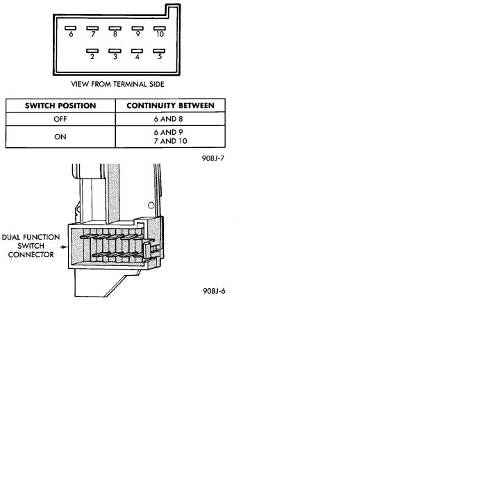
To test the hazard warning portion of the switch, first disconnect the negative battery cable, then remove the upper and lower steering column covers to gain access to the switch connector. Remove switch connector (Fig. 4). Using an ohmmeter, test for continuity between the terminals of the switch as shown in the following continuity chart (Fig. 5).
To test the cancellation portion of the switch:
(1)Reconnect battery and switch connector (Fig. 5).
(2)Connect voltmeter positive lead (+) to pin 8 and negative lead (-) to ground.
(3)Place ignition switch to the ON position. Voltmeter should read battery voltage. If no voltage is present, check feed wire to pin 8. If battery voltage is present continue with switch test.
RIGHT CANCELLATION TEST
(1)Connect one side of a jumper wire to pin 3 and the other end of jumper wire to ground.
(2)Connect the positive lead (+) of a voltmeter to pin 5 and the negative lead (-) to ground.
CAUTION: Do not allow pin 5 to become grounded during test, switch failure will result.
(3)With the ignition switch in the ON position, push the cancellation pawl down and read the voltmeter.
(4)The voltmeter should show at least 9 volts.
(5) If voltage is 0 to 8 volts the cancellation switch is defective. If voltage is 9 volts or more the cancellation switch is working correctly.
LEFT CANCELLATION TEST
(1)Connect one side of a jumper wire to pin 4 and the other end of jumper wire to ground.
(2)Connect the positive lead (+) of a voltmeter to pin 5 and the negative lead (-) to ground.
CAUTION: Do not allow pin 5 to become grounded during test, switch failure will result.
(3)With the ignition switch in the ON position, push the cancellation pawl up and read the voltmeter.
(4)The voltmeter should show at least 9 volts.
(5)If voltage is 0 to 8 volts the cancellation switch is defective. If voltage is 9 volts or more the cancellation switch is working correctly.
REMOTE TURN SIGNAL SWITCH TESTÐAA AND AJ BODIES
The remote turn signal switch is located on the left side of the instrument panel switch pod. To test, remove switch pod assembly from instrument panel. Using an ohmmeter, test for continuity between the terminals of the switch as shown in the following continuity chart (Fig. 6). The white 7 way connector next to the 14 way connector must be connected when performing continuity checks.
CANCELLATION SOLENOID TESTÐAG AND AJ BODIES
To test the turn signal cancellation solenoid:
(1)Remove switch pod from instrument panel.
(2)Connect one end of a jumper wire to the positive terminal of the battery, the other end to pin 6 of the turn signal switch 14 way connector.
(3)Place turn signal switch in the left turn mode.
(4)Take a second jumper wire and connect one end to a good ground. Momentarily touch the other end of the jumper wire to pin 11 or 14. The solenoid should energize, and return the switch to its center OFF position.
(5)Place turn signal switch in the right turn mode.
(6)Repeat step 4. The solenoid should energize, and return the switch to its center OFF position.
(7)If switch does not return to center in either direction, the switch is defective.
MULTI-FUNCTION SWITCHÐAA, AC, AP AND AY BODIES
REMOVAL
(1)Disconnect negative battery cable.
(2)Tilt column only remove tilt lever.
Ä |
|
TURN SIGNALS AND HAZARD WARNING FLASHER 8J - 3 |
|
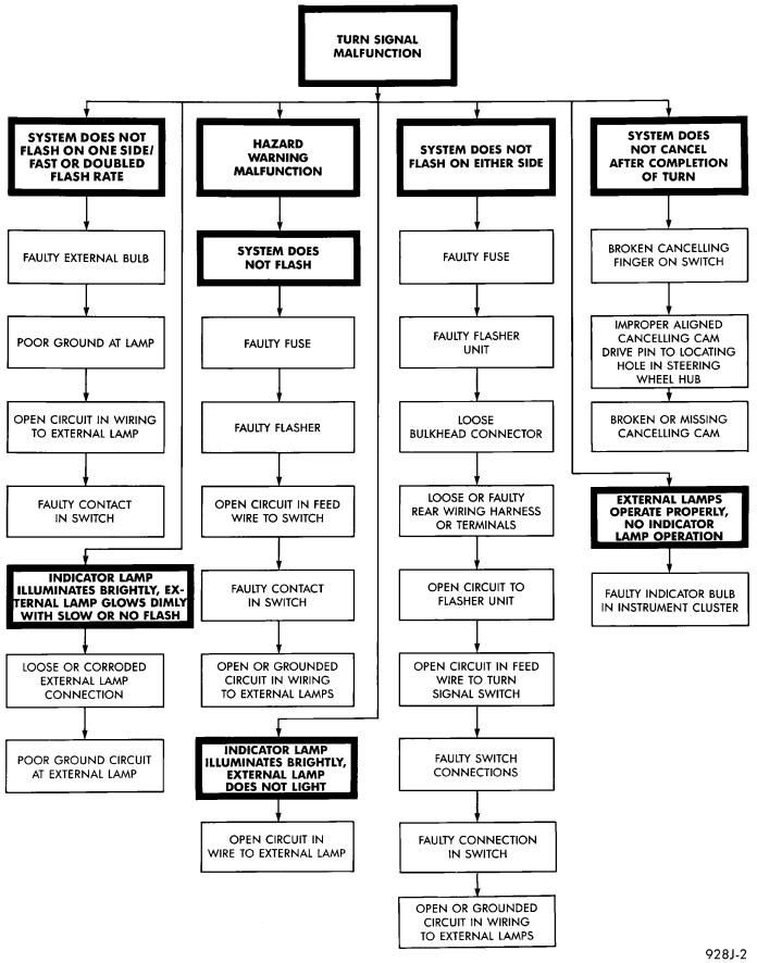
Fig. 1 Turn Signal and Hazard Warning Flasher Diagnosis
8J - 4 TURN SIGNALS AND HAZARD WARNING FLASHER |
|
Ä |
|
Fig. 2 Turn Signal and Hazard Switch Continuity
Fig. 3 Beam Select Switch Continuity
(3)Remove both upper and lower steering column shrouds.
(4)Remove multi-function switch tamper proof mounting screws (Fig.7).
(5)Gently pull switch away from column. Loosen connector screw. The screw will remain in the connector.
(6)Remove wiring connector from multi-function switch.
INSTALLATION
(1)Install wiring connector to switch and tighten connector retaining screw to 2 NIm (17 in. lbs.) torque.
(2)Mount multi-function switch to column and tighten retaining screws to 2 NIm (17 in. lbs.) torque.
Fig. 4 Dual-Function Switch Connector
Fig. 5 Hazard Warning Switch ContinuityÐAJ Body
(3)Install steering column covers. Tighten retaining screws to 2 NI (17 in. lbs.) torque.
(4)Tilt column only install tilt lever.
(5)Install negative battery cable.
(6)Check all functions of switch for proper opera-
tion.

Ä |
|
TURN SIGNALS AND HAZARD WARNING FLASHER 8J - 5 |
|
(5) Gently pull switch away from column. Release connector lock on the wiring connector, then remove the connector from the switch (Fig. 8).
Fig. 6 Remote Turn Signal Switch ContinuityÐAG
and AJ Bodies
Fig. 7 Multi-Function SwitchÐAA, AC, AP and AY
Bodies
DUAL-FUNCTION SWITCHÐAG AND AJ BODIES
REMOVAL
(1)Disconnect negative battery cable.
(2)Tilt column only remove tilt lever.
(3)Remove three attaching screws, in the upper and lower steering column covers and remove covers.
(4)Remove two tamper proof mounting screws.
Fig. 8 Dual-Function SwitchÐAG and AJ Bodies
INSTALLATION
(1)Install wiring connector to switch. Make sure that switch locking tab is fully seated in the wiring connector.
(2)Mount switch to column and torque screws to 2 NI (17 in. lbs.).
(3)Install steering column covers and torque screws to 2 NI (17 in. lbs.).
(4)Tilt column only install tilt lever.
(5)Re-install negative battery cable.
(6)Check all functions of switch for proper operation of the hazard warning and turn signal cancellation.
REMOTE TURN SIGNAL SWITCH REMOVALÐAG AND AJ BODIES
(1)Disconnect battery ground cable..
(2)Remove turn signal lever by pulling it straight out of the switch (Fig. 9).
(3)Remove two screws from the bottom of the switch pod that hold turn signal switch.
(4)Disconnect turn signal pigtail wire from headlamp switch at the 8-way connector.