

lab-inf-4_tasks / 7918
.pdfJOURNAL OF APPLIED PHYSICS |
VOLUME 94, NUMBER 12 |
15 DECEMBER 2003 |
Characterization of porous materials with a rigid frame via re¯ected waves
Z. E. A. Fellaha) and F. G. Mitri
National Institute of Health and Medical Research (INSERM U556), 151 Cours Albert Thomas, 69424 Lyon Cedex 03, France
C. Depollier
Laboratoire d'Acoustique de l'Universite du Maine, UMR±CNRS 6613, Université du Maine, Avenue Olivier Messiaen, 72085 Le Mans Cedex 09, France
S. Berger and W. Lauriks
Laboratorium voor Akoestiek en Thermische Fysica, Katholieke Universiteit Leuven, Celestijnenlaan 200 D, B-3001 Heverlee, Belgium
J. Y. Chapelon
National Institute of Health and Medical Research (INSERM U556), 151 Cours Albert Thomas, 69424 Lyon Cedex 03, France
~Received 15 July 2003; accepted 1 October 2003!
The inverse problem for waves re¯ected by porous material is solved at oblique incidence, and an inverse scattering calculation of porosity and tortuosity is given for air-saturated plastic foam samples. The interaction of the sound pulse with the ¯uid-saturated porous material is described by a time-domain equivalent ¯uid model. The sensitivity of the porosity and tortuosity is studied and it shows their effect on the re¯ection coef®cient at the ®rst interface. This study shows that porosity is much more sensitive than tortuosity to re¯ection, especially when the incident angle is less than its critical value, at which the re¯ection coef®cient vanishes. Some advantages and perspectives of this method are discussed. © 2003 American Institute of Physics. @DOI: 10.1063/1.1629386#
I. INTRODUCTION
Porous media ®lled with air,1±3 such as ®brous mats, plastic foams, and various felts, are used extensively in the automobile, aeronautical, and building industries to attenuate sound waves. Lately, low frequency ~i.e., in the 20± 600 kHz range! ultrasonic techniques have amply proven their worth as powerful tools by which to probe the acoustic properties of these materials.
Determining the properties of a medium using waves re¯ected by or transmitted through the medium is an inverse scattering problem.4 ± 8 Such problems are often approached by taking a physical model of the scattering process, generating a synthetic response for a number of assumed parameter values, and adjusting these parameters until a reasonable level of correspondence is attained between the synthetic response and the data observed.
Ultrasonic materials can often be characterized by measuring the attenuation coef®cient and phase velocity in the
frequency domain9±11 or by measuring transmitted and re- ¯ected waves in the time domain.4 ± 8,12 In the frequency do-
main, measurement of the attenuation coef®cient may be more robust than measurement of the phase velocity. In these situations, application of the Kramers±Kronig dispersion relations13 may allow the phase velocity to be determined from the measured attenuation coef®cient.
To ef®ciently cope with the speci®c problems that occur in transient acoustic ®eld propagation, new approaches are required.12,14 At present, most signal propagation analyses
a!Electronic mail: fellah@lyon.inserm.fr
are performed in the frequency domain using the Fourier transform, and the results are translated into the time domain, and vice versa. However this has several limitations. The ®rst one is that transformation is dif®cult to compute numerically with suf®cient accuracy for nonanalytical functions. For example, using the Fourier transform to obtain timedomain results for a lossy material is a more complicated approach than using a true time-domain analysis, and the numerical results are less accurate. The second disadvantage is that by working in the frequency domain, some numerical information is lost or hard to recover. For example, in the case of noisy data it may be dif®cult to reconstruct the chronological events of a signal by phase unwrapping. Consequently, it is dif®cult to obtain a deep understanding of transient signal propagation using the frequency-domain method.
A time-domain approach differs from frequency analysis in that the susceptibility functions that describe viscous and thermal effects are convolution operators that act on the velocity and pressure ®elds and therefore a different algebraic formalism must be applied to solve the wave equation. The time-domain response of the material is described by an instantaneous response and a ``susceptibility'' kernel responsible for memory effects. In the past, many authors have used fractional calculus as an empirical method to describe the properties of viscoelastic materials, e.g., Caputo15 and Bagley and Torvik.16 The observation that asymptotic expressions of stiffness and damping in porous materials are proportional to fractional powers of frequency suggests that time derivatives of fractional order might describe the behavior of sound waves in this kind of material, including relaxation and frequency dependence.
0021-8979/2003/94(12)/7914/9/$20.00 |
7914 |
© 2003 American Institute of Physics |
J. Appl. Phys., Vol. 94, No. 12, 15 December 2003 |
Fellah et al. |
7915 |
In this article, we solve the inverse problem for a slab of porous material with a rigid frame via re¯ected waves for different incident angles. An optimization procedure based on the least-square method is used that gives an estimate of the porosity and tortuosity of air-saturated porous materials. This method is based on a temporal equivalent ¯uid description of the propagation of sound in ¯uid-saturated porous material. This model was initially introduced by the authors6 to describe the memory effect of the wave during its propagation in the time domain. The advantage of this method is its simplicity compared to classical methods ~summarized in this article!.
The article is outlined as follows. In Sec. II, the parameters for ultrasonic transport in air-saturated porous material are de®ned and the classical experimental techniques used to estimate them are given. Section III describes a time-domain model and the basic equations of wave propagation in porous material. Section IV is devoted to the direct problem and expression of the re¯ection and transmission kernels in the time domain at oblique incidence. The sensitivity of the porosity and tortuosity and of the incident angle is discussed, showing the effect of each parameter on the re¯ection coef- ®cient at the ®rst interface. Section VI contains the numerical solution of the inverse problem based on the least-square method. Experimental validation that relies on ultrasonic measurement is discussed for air-saturated industrial plastic foams.
II. ULTRASONIC TRANSPORT PARAMETERS IN AIR-SATURATED POROUS MATERIAL
The quantities involved in sound propagation in porous materials can be de®ned locally, on a microscopic scale. However, this type of study is generally dif®cult because of the complicated geometry of the frames. Only the mean values of the quantities involved are of practical interest. Averaging must be performed on a macroscopic scale using volumes with dimensions suf®ciently large for the average to be signi®cant. At the same time, these dimensions must be much smaller than the wavelength. Even on a macroscopic scale, a description of sound propagation in porous material can be very complicated, since sound also propagates within the frame of the material. If the frame is motionless, the porous material can be replaced, macroscopically, by an equivalent ¯uid. If the porosity is low, the equivalent ¯uid has the same properties as air in porous material on a macroscopic scale.
In 1987, a substantial contribution was made by Johnson et al.,17 who put forth a theory of dynamic ¯uid ¯ow ~i.e., as a function of frequency! in porous media, thereby introducing the concept of dynamic tortuosity and permeability as well as viscous characteristic length. Originally, their research mainly focused on geophysical and petroleum indus-
try applications. The Johnson et al. model was used for different kinds of porous materials.1,4 ±13,17±24 For gas-saturated
porous media, Allard1 produced an analogous theory for ther-
mal effects by introducing the concept of thermal characteristic length. Lafarge et al.22,23 extended this theory by adding
the concept of thermal permeability which plays an important role in low frequency approximations.
A. Porosity
One important parameter which appears in theories of sound propagation in porous materials is porosity f. Porosity is the relative volume fraction of the air contained in the material. Unlike other parameters included in the description of different various phenomena occurring in acoustic propagation of porous media at a high frequency range, such as tortuosity,17 viscous characteristic length,17 and thermal characteristic length,1 or at a low frequency range, such as ¯ow resistivity17 and thermal permeability,22,23 porosity is a key parameter that plays an important role in propagation at all frequencies. As such, in studies of the acoustic properties of porous materials, it is extremely useful to be able to measure this parameter.
Beranek25 described an apparatus ~a porosimeter! used to measure the porosity of porous materials. This device was based on the equation of state for ideal gases at constant temperature ~i.e., Boyle's law!. Porosity can be determined by measuring the change in air pressure that occurs with a known change in volume of the chamber containing the sample. In the Beranek apparatus, changes in both pressure and volume are monitored using a U-shaped ¯uid-®lled manometer. An alternative technique for measuring porosity is a dynamic method proposed by Leonard.26 Techniques that use
water as the pore-®lling ¯uid, rather than air, are common in geophysical studies.27,28 Mercury has been used as the pore-
®lling ¯uid in other applications.29 However, for many materials, the introduction of liquids into the material is not appropriate. A similar device to that of Beranek's, that involves the use of an electronic pressure transducer, was introduced by Champoux et al.30 This device can be used to measure very slight changes in pressure accurately, and the output can be recorded by a computer. Recently, a simple alternative method for measuring porosity via waves re- ¯ected at the ®rst interface of a slab of air-saturated porous
material was proposed by the authors, and it gave good results for plastic foams7,8,31 and random bead packing.32
B. Tortuosity
Tortuosity a` is an important geometrical parameter included in the description of inertial coupling between the ¯uid and the structure of porous material in the high frequency range. This parameter represents the refraction index for porous materials.6 The concept of tortuosity is not recent, and it is found with different notations and meanings in previous studies. It is the structure form factor ks according to Zwikker and Kosten33 or parameter q2 according to Attenborough.34 In the case of cylindrical pores at angle q to the direction of propagation, a`51/cos2 q. In Carman's book,35 tortuosity is related to (cos q)21. An electrical method for measuring tortuosity was developed by Carman,35 Brown,36 and Johnson et al.,28 which, however, can only be used if the frame does not conduct electricity. The porous material is saturated with a conducting ¯uid, and the resistivity of the saturated material is measured between two electrodes using the relation

7916 J. Appl. Phys., Vol. 94, No. 12, 15 December 2003
a`5f |
rc |
, |
~1! |
|
r f |
||||
|
|
|
where rc and r f are the measured resistivities of the saturated material and the ¯uid, respectively. From relation ~1!, it can be seen that the tortuosity is independent of the shape of the pore cross sections. By introducing the concept of dynamic tortuosity for common porous materials with arbitrary pore shape, Johnson et al.17 gave another de®nition of tortuosity,
^um2 &V |
|
|
|
a`5lim ^um&V2 |
, |
v!`, |
~2! |
where v is the angular frequency and um is the microscopic velocity for a steady ¯ow of inviscid ¯uid. The symbol ^ &V denotes the average of the ¯uid volume V and the term ^um& is interpreted as macroscopic velocity. Johnson et al.17 proposed a method for measuring tortuosity using super¯uid 4He as the pore ¯uid.
Tortuosity takes a low value (a`51) for porous material with straight pores, and high values (a`52,3) for porous media with high resistivity. This parameter can also be evaluated using ultrasonics for measurement in the frequency domain,9±11 from the attenuation or phase velocity, or in the
time domain by solving the inverse problem in the transmitted4 ± 6 or re¯ected mode7,8,31,32
III. MODEL
In porous material acoustics, a distinction can be made between two situations depending on whether the frame is moving or not. In the ®rst case, wave dynamics due to the solid frame±¯uid coupling are clearly described by Biot theory.37,38 In air-saturated porous media, the structure is generally motionless and the waves propagate only in the ¯uid. This case is described by the equivalent ¯uid model which is a particular case of the Biot model, in which ¯uid± structure interactions are taken into account in two frequency response factors: dynamic tortuosity of the medium a~v! given by Johnson et al.17 and dynamic compressibility of the air in the porous material b~v! given by Allard.1 In the frequency domain, these factors multiply the ¯uid's density and compressibility, respectively, and represent the deviation of the ¯uid's behavior in free space as the frequency increases. In the time domain, they act as operators and in the asymptotic domain ~high frequency approximation! with
their expressions given4 ± 8,12 by |
|
|
|
|
|
|
||||||||||
Äa~t !5a`Sd~t !1 |
2 |
S |
h |
D1/2t21/2D, |
|
|
|
|
~3! |
|||||||
L |
pr f |
|
|
|
|
|||||||||||
Ä |
|
|
2~g21 ! |
|
|
h |
1/2 |
|
|
|
|
|
||||
|
|
|
|
|
|
21/2 |
|
. |
~4! |
|||||||
|
|
|
|
|
|
|
|
|
|
|
|
|
||||
b~t !5 |
S |
d~t !1 |
L8 |
SpPrr f D |
|
t |
|
D |
||||||||
|
|
|
|
|
|
|
||||||||||
In these equations, d(t) is the Dirac function, Pr is the Prandtl number, h and r f are ¯uid viscosity and ¯uid density, respectively, and g is the adiabatic constant. The relevant physical parameters of the model are the medium's tortuosity a` initially introduced by Zwikker and Kosten,33 and viscous and the thermal characteristic lengths L and L8 intro-
Fellah et al.
duced by Johnson et al.17 and Allard.1 In this model time convolution of t21/2 with a function is interpreted as a semiderivative operator according to the de®nition of the fractional derivative of order n given in work by Samko and colleagues39
Dn@x~t !#5 G~21 n! |
E0 ~t2u !2n21x~u !du, |
~5! |
|
|
|
t |
|
where G(x) is the gamma function.
In this framework, the basic equations of our model obtained from the conservation of momentum and conservation of mass can be written as
r f Äa~t !* |
]vi |
52¹i p |
|
|||||
]t |
|
|||||||
|
|
|
|
|
|
|
||
and |
|
|
|
|
|
|
|
|
Ä |
! |
|
]p |
|
|
|||
b~t |
|
|
|
|||||
|
|
|
* |
|
52¹"v, |
~6! |
||
|
Ka |
|
]t |
|||||
where the asterisk * denotes the time convolution operation, p is the acoustic pressure, v is the particle velocity, and Ka is the bulk modulus of air. The ®rst equation is the Euler equation, the second one is the constitutive equation.
In the plane ~xoz! constitutive Eqs. ~6! can be written as
|
|
|
]v |
x |
~x,z,t ! |
|
|
2r a |
` |
|
S |
h |
D |
1/2 |
|
|
|
|
|
|||||||||||||||||
|
|
|
|
|
|
|
|
|
|
|
|
|
|
|
|
|
||||||||||||||||||||
r f a` |
|
|
|
|
|
|
1 |
|
|
|
f |
|
|
|
|
|
|
|
|
|
|
|
|
|
|
|||||||||||
|
|
|
]t |
|
|
L |
|
|
|
|
pr f |
|
|
|
|
|
|
|
|
|
|
|
||||||||||||||
|
|
3 E |
t |
|
]vx~x,z,t8!/]t8 |
|
|
dt852 |
]p~x,z,t ! |
|
, |
|
|
|||||||||||||||||||||||
|
|
|
|
|
|
|
|
|
|
|
|
|
|
|
|
|
|
|
|
|
|
|
|
|||||||||||||
|
|
|
|
|
|
|
|
|
|
|
|
|
|
|
|
|
|
]x |
|
|
|
|||||||||||||||
|
|
|
At2t8 |
|
|
|
|
|
|
|
|
|||||||||||||||||||||||||
|
|
|
0 |
|
|
|
|
|
|
S |
|
|
|
D |
|
|
|
|
|
|
|
|
|
|
|
|||||||||||
|
|
|
]v |
z |
~x,z,t ! |
|
|
2r a |
` |
|
h |
1/2 |
|
|
|
|
|
|||||||||||||||||||
|
|
|
|
|
|
|
|
|
|
|
|
|
|
|
|
|
||||||||||||||||||||
r f a` |
|
|
|
|
|
|
1 |
|
|
|
f |
|
|
|
|
|
|
|
|
|
|
|
|
|
||||||||||||
|
|
|
]t |
|
|
|
L |
|
|
|
pr f |
|
|
|
|
|
|
|
|
|
|
|
||||||||||||||
|
|
3 E |
t |
|
]vz~x,z,t8!/]t8 |
|
dt852 |
]p~x,z,t ! |
, |
~7! |
||||||||||||||||||||||||||
|
|
|
|
|
|
|
|
|
|
|
|
|
|
|
|
|
|
|
|
|||||||||||||||||
|
|
|
|
|
|
|
|
|
|
|
|
|
|
|
|
|
]z |
|||||||||||||||||||
|
|
|
At2t8 |
|
|
|
|
|
||||||||||||||||||||||||||||
|
|
|
0 |
|
|
|
|
|
S |
|
|
|
|
|
|
|
D |
|
|
|
|
|
|
|||||||||||||
1 ]p~x,z,t ! |
|
2~g21 ! |
|
|
h |
|
|
|
1/2 |
|
|
|
|
|
||||||||||||||||||||||
|
|
|
|
|
|
|
|
|
|
|
|
|||||||||||||||||||||||||
|
|
|
|
|
1 |
|
|
|
|
|
|
|
|
|
|
|
|
|||||||||||||||||||
Ka |
]t |
|
KaL8 |
|
|
pr f Pr |
|
|
|
|
|
|
||||||||||||||||||||||||
|
|
3 E |
t |
|
]p~x,z,t8!/]t8 |
|
|
|
|
|
|
|
|
|
|
|
]vx~x,z,t ! |
|
|
]vz~x,z,t ! |
||||||||||||||||
|
|
|
|
|
|
|
|
|
|
|
|
|
|
dt852 |
|
|
|
|
|
|
|
|
2 |
|
, |
|||||||||||
|
|
|
|
|
|
|
|
|
|
|
|
|
|
|
|
|
|
|
|
]x |
|
]z |
||||||||||||||
|
|
|
|
|
At2t8 |
|
|
|
|
|
|
|
||||||||||||||||||||||||
|
|
|
0 |
|
|
|
|
|
|
|
|
|
|
|
|
|
|
|
|
|
|
|
|
|
|
|
|
|||||||||
where vx and vz are the components of particle velocity along axes x and z.
In these equations, the convolutions express the dispersive nature of the porous material. They take into account memory effects due to the fact that the medium's response to wave excitation is not instantaneous but instead needs some time to take effect.
IV. DIRECT PROBLEM
The direct scattering problem involves determining the scattered ®eld as well as the internal ®eld that arises when a known incident ®eld impinges on the porous material with known physical properties. To compute the solution of the direct problem one needs to know the Green's function4,40 of
J. Appl. Phys., Vol. 94, No. 12, 15 December 2003 |
Fellah et al. |
7917 |
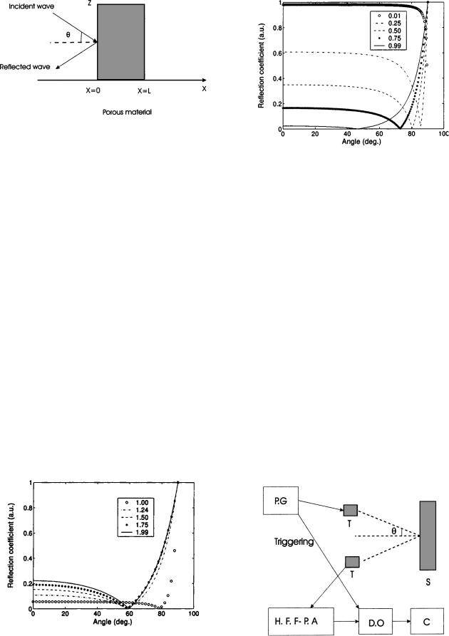
FIG. 1. Problem geometry.
the modi®ed wave equation in a porous medium. In this case, the internal ®eld is given by the time convolution of the Green's function with the incident wave, and the re¯ected and transmitted ®elds are deduced from the internal ®eld and the boundary conditions.
Here in Sec. IV some notation is introduced. The problem geometry is shown in Fig. 1. A homogeneous porous material occupies region 0<x<L. This medium is assumed to be isotropic and to have a rigid frame. A short sound pulse impinges at oblique incidence on the medium from the left, giving rise to an acoustic pressure ®eld p(x,z,t) and an acoustic velocity ®eld v(x,z,t) within the material, which satisfy the system of Eqs. ~7! and can be written as
|
|
|
]vx~x,z,t ! |
1bD1/2@vx~x,z,t !#52 |
|
]p~x,z,t ! |
|
|||||||
|
a |
|
|
|
|
|
|
|
, |
~8! |
||||
|
|
|
]t |
|
|
|||||||||
|
|
|
|
|
|
|
|
|
]x |
|
||||
|
|
|
]vz~x,z,t ! |
1bD1/2@vz~x,z,t !#52 |
]p~x,z,t ! |
|
||||||||
|
a |
|
|
|
|
|
, |
~9! |
||||||
|
|
|
]t |
|
||||||||||
|
|
|
|
|
|
|
|
|
]z |
|
||||
|
]p~x,z,t ! |
|
|
|
|
|
|
|
|
|
||||
d |
|
|
|
|
1 f D1/2@ p~x,z,t !# |
|
|
|
|
|
||||
|
]t |
|
|
|
|
|
|
|||||||
|
|
|
|
|
|
|
|
|
|
|
|
|
||
|
|
|
|
]vx~x,z,t ! |
]vz~x,z,t ! |
|
|
|
|
|
||||
|
52 |
|
|
|
2 |
|
, |
|
|
|
|
~10! |
||
|
|
]x |
|
|
|
|
|
|
||||||
|
|
|
|
|
|
|
]z |
|
|
|
|
|
||
with
FIG. 3. Variation of the re¯ection coef®cient at the ®rst interface with the incident angle for ®xed tortuosity value a`51.1 and for different values of porosity f50.99 ~solid line!, 0.75 ~star!, 0.50 ~dashed line!, 0.25 ~dashdotted line!, and 0.01 ~circle!.
|
|
|
|
|
|
|
|
|
2r a |
` |
|
h |
1/2 |
|
|
|
|
|
||||||||
|
a5r f a` , b5 |
|
|
|
f |
|
S |
|
|
D |
, |
|
|
|
|
|
||||||||||
|
|
L |
|
|
r f |
|
|
|
|
|
||||||||||||||||
1 |
|
, |
|
|
|
|
|
|
|
|
|
|
|
|
|
|
|
|
|
|
|
|
|
|||
|
d5 |
|
|
|
|
|
|
|
|
|
|
|
|
|
|
|
|
|
|
|
|
|
|
|
||
Ka |
|
|
|
|
|
|
|
|
|
|
|
|
|
|
|
|
|
|
|
|
|
|||||
and |
|
|
|
|
|
|
|
|
|
|
|
|
|
|
|
|
|
|
|
|
|
|||||
|
|
2~g21 ! |
|
|
|
h |
|
|
|
1/2 |
|
|
|
|
|
|
|
|
|
|||||||
|
f 5 |
S |
|
|
|
D . |
|
|
|
|
|
|
|
|
|
|||||||||||
|
|
|
|
|
|
|
|
|
|
|
|
|
|
|
|
|||||||||||
KaL8 |
|
r f Pr |
|
|
|
|
|
|
|
|
|
|||||||||||||||
|
In the region of x<0, the incident pressure wave is given |
|||||||||||||||||||||||||
by |
|
|
S |
|
|
|
|
|
|
|
|
|
|
D |
|
|
|
|||||||||
|
|
|
|
|
|
|
|
|
|
|
c0 |
|
|
|
c0 |
|
|
|
||||||||
|
pi~x,z,t !5pi |
|
t2 |
|
x cos u |
z sin u |
|
|
, |
|
~11! |
|||||||||||||||
|
|
|
|
|
|
|
|
|
2 |
|
|
|
|
|||||||||||||
where c0 is the |
velocity |
of |
the free ¯uid |
(x<0); c0 |
||||||||||||||||||||||
5A |
Ka /r f |
. |
|
|
|
|
|
|
|
|
|
|
|
|
|
|
|
|
|
|
|
|
|
|||
|
In the region of 0<x<L, the pressure wave is given by |
|||||||||||||||||||||||||
|
|
|
|
|
|
S |
|
|
|
|
|
|
c8 |
|
|
|
c8 |
8 |
D |
|
|
|||||
|
p~x,z,t !5p t2 |
x cos u8 |
z sin u |
|
|
, |
~12! |
|||||||||||||||||||
|
|
|
|
|
|
|
|
|
2 |
|
|
|
|
|||||||||||||
FIG. 2. Variation of the re¯ection coef®cient at the ®rst interface r with the incident angle u for ®xed porosity value f50.9 and for different values of tortuosity a`51.99 ~solid line!, 1.75 ~star!, 1.5 ~dashed line!, 1.24 ~dashdotted line!, and 21 ~circle!.
FIG. 4. Experimental setup of ultrasonic measurements in re¯ected mode. PG: Pulse generator, HFFPA: high frequency ®ltering preampli®er, DO: digital oscilloscope, C: computer, T: transducer, S: sample.
7918 J. Appl. Phys., Vol. 94, No. 12, 15 December 2003
TABLE I. Measured values of porosity and tortuosity using classical methods ~after Refs. 4 ± 6 and 9±11!.
Material |
M1 |
M2 |
M3 |
|
|
|
|
Tortuosity |
1.1 |
1.1 |
1.5 |
Porosity |
0.95 |
0.99 |
0.86 |
|
|
|
|
|
|
|
|
where c8 is the velocity in the porous material (0<x<L), and the refraction angle u8 is given by Descartes±Snell law1 as
sin u |
|
sin u8 |
|
||
|
5 |
|
|
. |
~13! |
c0 |
c8 |
||||
To simplify the system of Eqs. ~7!, we can then use the following property:
]sin u ]
|
|
52 |
|
|
|
|
|
|
|
|
|
, |
|
|
|
~14! |
||||
|
]z |
|
|
c0 |
]t |
|
|
|||||||||||||
which implies |
|
|
|
|
|
|
|
|
|
|
|
|
|
|||||||
|
]vz |
52 |
sin u ]vz |
|
|
|
||||||||||||||
|
|
|
|
|
|
|
|
|
|
|
|
|
|
|||||||
|
]z |
c0 |
|
|
|
]t |
|
|
|
|||||||||||
and |
|
|
|
|
|
|
|
|
|
|
|
|
|
|
|
|
|
|||
|
]p |
|
|
sin u ]p |
|
|
|
|||||||||||||
|
|
52 |
|
|
|
|
|
|
|
. |
|
|
~15! |
|||||||
|
]z |
c0 |
|
|
|
|
]t |
|
|
|||||||||||
From Eqs. ~9! and ~15!, we then obtain the relation, |
|
|||||||||||||||||||
|
]vz |
|
|
|
sin2 u |
]p |
|
|||||||||||||
|
|
|
|
52 |
|
|
|
|
|
|
~a1bD21/2!21* |
|
. |
~16! |
||||||
|
]z |
c |
2 |
|
|
|
|
|
||||||||||||
|
|
|
|
0 |
|
|
|
|
|
|
|
|
]t |
|
||||||
|
|
|
|
|
|
|
|
|
|
|
|
|
|
|
|
|
|
|
||
Using Eqs. ~8!, ~10!, and ~16!, the equation system @Eqs. ~8!±~10!# can thus be simpli®ed to
|
]vx~x,z,t ! |
1bD1/2@vx~x,z,t !#52 |
]p~x,z,t ! |
|
|
a |
|
|
, |
~17! |
|
]t |
|
||||
|
|
]x |
|
||
Fellah et al.
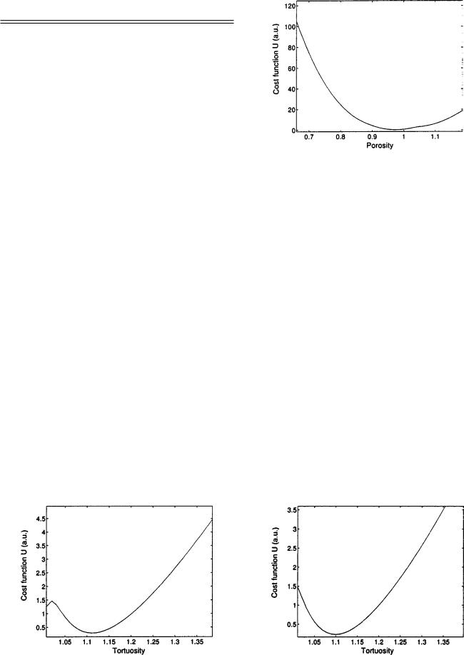
FIG. 6. Variation of cost function U with the porosity for plastic foam M1.
|
]p~x,z,t ! |
|
|
|
|
|
|
|
||
d |
|
|
1 f D1/2@ p~x,z,t !# |
|
|
|
||||
]t |
|
|
|
|
||||||
|
|
|
|
|
|
|
|
|
|
|
|
|
]vx~x,z,t ! |
sin2 u |
~a1bD21/2!21 |
|
]p~x,z,t ! |
||||
|
52 |
|
|
1 |
|
|
* |
|
. |
|
|
|
]x |
c |
2 |
|
|||||
|
|
|
|
0 |
|
|
]t |
|||
|
|
|
|
|
|
|
|
|
|
|
|
|
|
|
|
|
|
|
|
~18! |
|
From Eqs. ~17! and ~18!, we derive the generalized lossy wave equation in the time domain along the x axis as
]2 p~x,z,t ! |
]2 p~x,z,t ! |
2BD3/2@ p~x,z,t !# |
|||
|
|
2A |
|
|
|
]x2 |
|
|
]t2 |
||
|
|
|
|
||
|
]p~x,z,t ! |
|
|||
2C |
|
|
|
50, |
~19! |
|
]t |
|
|||
|
|
|
|
|
|
where coef®cients A, B, and C are constants given, respectively, by
1 |
~a`2sin2 u!, |
|
|
|
|
|
||||||
A5 |
|
|
|
|
|
|
|
|||||
c |
2 |
|
|
|
|
|
||||||
|
0 |
|
|
|
|
|
|
|
|
|
|
|
|
2a` |
|
|
|
1 |
|
g21 |
|||||
|
r f h |
|
|
|||||||||
B5 |
|
A |
|
S |
|
1 |
|
|
|
D, |
||
Ka |
p |
L |
A |
|
L8 |
|||||||
Pr |
||||||||||||
and
FIG. 5. Variation of cost function U with the tortuosity for plastic foam M1.
FIG. 7. Variation of cost function U with the tortuosity for plastic foam M2.

J. Appl. Phys., Vol. 94, No. 12, 15 December 2003 |
|
4a`~g21 !h |
|
C5 KaLL8APr . |
~20! |
The ®rst one is related to the velocity of the wave projected along the x axis, c5c0 /Aa`2sin2 u. The other coef®cients are essentially dependent on the characteristic lengths, L and L8, and express viscous and thermal interactions between the ¯uid and structure. Constant B governs signal dispersion while C is responsible for wave attenuation. Obviously, these three coef®cients can be used to determine parameters a` , L, and L8. One way in which to solve Eq. ~19! with suitable initial and boundary conditions is by using the Laplace transform. The approach is quite simple although the inverse Laplace transform involves tedious calculations.40 A suitable setting for introducing a time-domain solution of the modi- ®ed wave propagation, Eq. ~19!, is provided by the following model.
If the incident sound wave is launched in region x<0, then the expression of the pressure ®eld in the region on the left of the material is the sum of the incident and re¯ected
®elds, |
|
|
|
|
p1~x,t,u!5pi St2 |
x cos u |
D1pr St1 |
x cos u |
D, x,0. |
|
|
|||
c0 |
c0 |
|||
|
|
|
|
~21! |
Here, p1(x,t,u) is the ®eld in region x,0, and pi and pr denote the incident and re¯ected ®elds, respectively.
The incident and re¯ected ®elds are related by the scattering operator ~i.e., the re¯ection operator! for the material.
This is an integral operator represented by |
|
|
|
|
||||||||||
p |
r |
~x,t,u!5 E |
t |
Ä |
|
i |
S |
t2t1 |
x cos u |
D |
dt |
|
||
|
|
|
|
|
||||||||||
|
|
R~t,u!p |
|
|
c0 |
|
||||||||
|
|
0 |
|
|
|
|
|
|
|
|||||
|
|
Ä |
|
i |
|
|
!*dSt1 |
|
x cos u |
D. |
|
|||
|
|
|
|
|
|
|
|
|
||||||
|
|
5R~t,u!*p |
~t |
|
c0 |
|
~22! |
|||||||
In Eq. ~22! |
Ä |
function R is the re¯ection kernel for incidence |
from the left. Note that the lower limit of integration in Eqs. ~22! is set to 0, which is equivalent to assuming that the incident wave front impinges on the material at t50.
The expression for the re¯ection-scattering operator taking into account n-multiple re¯ections in the material is
given by |
S11E Dn>0 |
S11E D |
|
F |
S |
c D |
|
|||||||||||
|
|
|
2n |
|
||||||||||||||
Ä |
|
|
1 |
2E |
( |
|
12E |
|
F t,2n |
L |
|
|||||||
|
|
|
|
|
|
|
|
|
|
|
|
|
|
|
|
|||
R~t,u!5 |
|
|
|
|
|
|
|
|
|
|
|
|
|
|
||||
|
|
|
2F St,~2n12 ! |
L |
DG, |
|
|
|
|
|
~23! |
|||||||
|
|
|
c |
|
|
|
|
|
||||||||||
with |
|
|
|
|
|
|
|
|
|
|
|
|
|
|
|
|
||
|
fA |
|
|
|
|
|
|
|
|
|
|
|
|
|
|
|||
E5 |
12sin2 u/a` |
, |
|
|
|
|
|
|
|
|
|
~24! |
||||||
A |
|
cos u |
|
|
|
|
|
|
|
|
|
|||||||
a` |
|
|
|
|
|
|
|
|
|
|||||||||
and F is the medium's Green function4,40 given by |
|
|||||||||||||||||
|
|
|
0 |
|
if 0<t<k, |
|
|
|
|
|
|
|||||||
F~t,k !5 HJ~t !1D*0t2kh~t,j!dj if t>k, |
~25! |
|||||||||||||||||
with
|
|
|
|
|
|
Fellah et al. |
7919 |
|
|
b8 |
|
k |
|
b82k2 |
|
||
J~t !5 |
|
|
|
|
expS2 |
|
D, |
~26! |
4A |
|
~t2k !3/2 |
16~t2k ! |
|||||
p |
||||||||
where h(t,j) has the following form:
1 |
|
|
|
|
|
1 |
|
|
|
|
|
1 |
|
|
|
|||
h~j,t!52 |
|
|
|
|
|
|
|
|
|
|
|
|
|
|
||||
4p3/2 |
A |
|
|
|
|
|
j3/2 |
|
||||||||||
|
~t2j!22k2 |
|
||||||||||||||||
21 |
|
|
|
S |
2 |
|
|
|
D |
|
||||||||
3 E |
1 |
exp |
2 |
x~m,t,j! |
|
|
|
|
||||||||||
|
|
mdm |
|
|
|
|
||||||||||||
3@x~m,t,j!21 # |
|
, |
~27! |
|||||||||||||||
|
|
|
||||||||||||||||
A |
|
|
||||||||||||||||
12m2 |
||||||||||||||||||
and x(m,t,j)5@DmA |
|
1b8(t2j) #2/8j, |
b8 |
|||||||||||||||
(t2j)22k2 |
||||||||||||||||||
5Bc20Ap, c85C.c20 and D5b8224c8. In most cases of air-saturated porous materials, multiple re¯ection effects may
be negligible because of the high attenuation of sound waves in these media. This depends on the thickness L and physical properties of the porous material. For common air-saturated porous materials, only the wave re¯ected by the ®rst interface is seen experimentally32 and all contributions from the bulk of the porous material are neglected. So, by taking into account only the ®rst re¯ections at interfaces x50 and x 5L, the expression of the re¯ection operator will be given by
Ä |
|
|
|
|
|
|
~28! |
R~t,u!5r~t,u!1R~t,u!, |
|
|
|||||
with |
|
|
|
||||
r~t,u!5S |
12E |
Dd~t ! |
|
|
|
||
11E |
|
|
|
||||
and |
|
|
|
||||
|
|
4E~12E ! |
2L |
|
|
||
R~t,u!52 |
|
F St, |
|
D, |
~29! |
||
~11E !3 |
c |
||||||
with r(t,u) the instantaneous response of the porous material corresponding to the re¯ection contribution at the ®rst interface (x50). R(t,u) is equivalent to re¯ection at interface x5L, which is the bulk contribution to re¯ection. The part of the wave corresponding to r(t,u) is not subjected to dispersion but simply multiplied by the factor (12E)/(1 1E).
The re¯ection coef®cient at the ®rst interface vanishes for a critical angle uc ,
r~t,u!50)sin uc5Aa`~a`2f2 !.
Figure 2 shows the variation of the re¯ection coef®cient at ®rst interface r with incident angle u for ®xed porosity value of f50.9, and for different values of tortuosity, a`51.99 ~solid line!, 1.75 ~star!, 1.5 ~dashed line!, 1.24 ~dash-dotted line!, and 1 ~circle!.
Figure 3 shows the variation of r with the incident angle, for a ®xed tortuosity of a`51.1, and for different values of porosity f50.99 ~solid line!, 0.75 ~star!, 0.50 ~dashed line!, 0.25 ~dash-dotted line!, and 0.01 ~circle!.
7920 |
J. Appl. Phys., Vol. 94, No. 12, 15 December 2003 |
Fellah et al. |
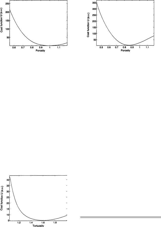
FIG. 8. Variation of cost function U with the porosity for plastic foam M2.
FIG. 10. Variation of cost function U with the porosity for plastic foam M3.
When the incident angle is u,uc , the re¯ection coef®- cient decreases slowly with the incident angle, and when it is u.uc , the re¯ection coef®cient increases quickly with the angle. It can also be seen from Figs. 2 and 3 that the sensitivity of porosity variation is more important than the sensitivity of tortuosity on the re¯ection coef®cient at the ®rst interface.
V. INVERSE PROBLEM
The propagation of acoustic waves in a slab of porous material in the high frequency asymptotic domain is characterized by four parameters: porosity f, tortuosity a` , viscous characteristic length L, and thermal characteristic length L8, the values of which are crucial to the behavior of sound waves in such materials. It is of some importance to work out new experimental methods and ef®cient tools for estimation of them. The basic inverse problem associated with the slab may be stated as follows: from measurement of the signals transmitted and/or re¯ected outside the slab, ®nd the values of the medium's parameters. The inverse problem has been solved in transmission mode in Refs. 4 ± 6 and an estimate of a` , L, and L8 made therein that gives a good correlation between experience and theory. Porosity was not estimated in this mode because of its weak sensitivity. Porosity was estimated in re¯ected mode in our previous
FIG. 9. Variation of cost function U with the tortuosity for plastic foam M3.
studies7,8,31,32 by solving the inverse problem at normal8 and oblique incidence31 for a ®xed value of tortuosity. Porosity and tortuosity were measured7,32 simultaneously for plastic foams and air-saturated random packings of beads by measuring re¯ected waves for each pair of incident angles.
In this article, we determine the porosity and tortuosity by solving the inverse problem for waves re¯ected by the ®rst interface, and by taking into account experimental data for all measured incident angles.
The inverse problem is to ®nd values of parameters f and a` , which minimize the function
U~f,a` !5 ( ( @ pr~x,ui ,ti ! |
|
ui ti |
|
2r~ui ,ti !*pi~x,ui ,ti !#2, |
~30! |
where pr(x,ui ,ti) represents the discrete set of values of the experimental re¯ected signal for different incident angles ui , r(ui ,ti) is the re¯ection coef®cient at the ®rst interface, and pi(x,ui ,ti) is the experimental incident signal. The term r(ui ,ti)*pi(x,ui ,ti) represents the predicted re¯ected signal. The inverse problem is solved numerically by the leastsquare method.
Experiments were performed in air with two broadband Ultran NCT202 transducers with 190 kHz center frequency in air and 6 dB bandwith that extends from 150 to 230 kHz. An optical goniometer was used to position the transducers. Pulses of 400 V were provided by a 5052PR Panametrics pulser/receiver. The signals received were ampli®ed to 90 dB and ®ltered above 1 MHz to avoid high frequency noise. Electronic interference was removed by 1000 acquisition averages. The experimental setup is shown in Fig. 4. The duration of the signal plays an important role: its spectrum must verify the condition of the high frequency approximation referred to in Sec. IV.
TABLE II. Reconstructed values of porosity and tortuosity by solving the inverse problem.
Material |
M1 |
M2 |
M3 |
|
|
|
|
Tortuosity |
1.12 |
1.1 |
1.6 |
Porosity |
0.96 |
0.99 |
0.85 |
|
|
|
|
|
|
|
|
J. Appl. Phys., Vol. 94, No. 12, 15 December 2003 |
Fellah et al. |
7921 |
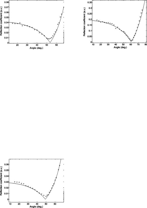
FIG. 11. Comparison between the simulated re¯ection coef®cient at the ®rst interface using reconstructed values of the porosity and tortuosity ~solid line! and experimental data for the re¯ection coef®cient at the ®rst interface ~circle! for plastic foam M1.
FIG. 13. Comparison between the simulated re¯ection coef®cient at the ®rst interface using reconstructed values of the porosity and tortuosity ~solid line! and experimental data for the re¯ection coef®cient at the ®rst interface ~circle! for plastic foam M3.
Let us consider three samples of plastic foam, M1, M2,
and M3. Their tortuosity and porosity were measured using classical methods4 ± 6,9±11 ~Table I!. We solved the inverse
problem for these samples via waves re¯ected at the ®rst interface and for different incident angles. Figures 5 and 6, 7 and 8, and 9 and 10 show variation of the cost function, U, with the tortuosity and porosity for samples M1, M2, and M3, respectively. The reconstructed values of porosity and tortuosity corresponding to the positions of the minima of these cost functions are given in Table II. Figures 11±13 show comparisons between simulated re¯ection coef®cients at the ®rst interface using reconstructed values of the porosity and tortuosity ~solid line! and experimental data for the re¯ection coef®cient at the ®rst interface ~circle! for plastic foams M1, M2, and M3, respectively. The correspondence between experiment and theory is good, which leads us to conclude that this method based on solution of the inverse problem is appropriate for estimating the porosity and tortuosity of porous materials with a rigid frame.
FIG. 12. Comparison between the simulated re¯ection coef®cient at the ®rst interface using reconstructed values of the porosity and tortuosity ~solid line! and experimental data for the re¯ection coef®cient at the ®rst interface ~circle! for plastic foam M2.
VI. CONCLUSION
In this article, an inverse scattering estimate of the porosity and tortuosity was given by solving the inverse problem for waves re¯ected by the ®rst interface, and by taking into account experimental data for all measured incident angles. The inverse problem is solved numerically by the least-square method. The reconstructed values of the porosity and tortuosity are close to those using classical methods. Generally, it is easy to evaluate the tortuosity from transmitted waves, but that is not the case for porosity because of its weak sensitivity in transmitted mode. This method is an alternative to the usual method that involves the use of a porosimeter, introduced by Beranek, and improved by Champoux et al. or the other ultrasonic methods based on transmitted mode.
The direct problem is based upon the propagation equation in the time domain in a slab of porous material with a rigid frame in the high frequency asymptotic domain. Interaction of the sound pulse with the ¯uid-saturated porous material was described by a time-domain equivalent ¯uid model.
The sensitivity of the porosity and tortuosity was studied and it showed their effect on the re¯ection coef®cient at the ®rst interface. This study has shown that porosity is much more sensitive than tortuosity to re¯ection, especially when the incident angle is less than its critical value, at which the re¯ection coef®cient vanishes.
We hope, in the future, to extend this method to porous media with an elastic frame, such as cancellous bone saturated with viscous ¯uid, in order to estimate other parameters which play an important role in acoustic propagation. The advantage of the data concept using waves re¯ected by the ®rst interface is its simple analysis, and similar to the transmitted wave concept which, however, is more complicated. The wave re¯ected by the ®rst interface is not subject to dispersion but is simply attenuated, its frequency and temporal bandwidths are the same as the incident signal, and experimental detection of it is easy for resistive media compared to transmitted data.
7922 J. Appl. Phys., Vol. 94, No. 12, 15 December 2003
1J. F. Allard, Propagation of Sound in Porous Media: Modeling Sound Absorbing Materials ~Chapman and Hall, London, 1993!.
2K. Attenborough, J. Acoust. Soc. Am. 81, 93 ~1987!.
3K. Attenborough, Acta Acustica united with Acustica 1, 213 ~1993!.
4Z. E. A. Fellah, C. Depollier, and M. Fellah, J. Sound Vib. 244, 359 ~2001!.
5Z. E. A. Fellah, C. Depollier, and M. Fellah, Acust. Acta Acust. 88, 34 ~2002!.
6Z. E. A. Fellah, M. Fellah, W. Lauriks, and C. Depollier, J. Acoust. Soc. Am. 113, 61 ~2003!.
7Z. E. A. Fellah, S. Berger, W. Lauriks, C. Depollier, C. AristeÂgui, and J.-Y. Chapelon, J. Acoust. Soc. Am. 113, 2424 ~2003!.
8Z. E. A. Fellah, S. Berger, W. Lauriks, C. Depollier, and M. Fellah, J. Appl. Phys. 93, 296 ~2003!.
9P. Leclaire, L. Kelders, W. Lauriks, C. Glorieux, and J. Thoen, J. Acoust. Soc. Am. 99, 1944 ~1996!.
10P. Leclaire, L. Kelders, W. Lauriks, M. Melon, N. Brown, and B. Castagnede, J. Appl. Phys. 80, 2009 ~1996!.
11P. Leclaire, L. Kelders, W. Lauriks, J. F. Allard, and C. Glorieux, Appl. Phys. Lett. 69, 2641 ~1996!.
12Z. E. A. Fellah and C. Depollier, J. Acoust. Soc. Am. 107, 683 ~2000!.
13Z. E. A. Fellah, S. Berger, W. Lauriks, and C. Depollier, J. Sound. Vib. ~to be published!.
14T. L. Szabo, J. Acoust. Soc. Am. 96, 491 ~1994!.
15M. Caputo, J. Acoust. Soc. Am. 60, 634 ~1976!.
16R. L. Bagley and P. J. Torvik, J. Rheol. 30, 133 ~1983!.
17D. L. Johnson, J. Koplik, and R. Dashen, J. Fluid Mech. 176, 379 ~1987!.
18D. M. J. Smeulders, R. L. G. M. Eggels, and M. E. H. Van Dongen, J. Fluid Mech. 245, 211 ~1992!.
19Y. Champoux and J. F. Allard, J. Appl. Phys. 70, 1975 ~1991!.
20J. F. Allard, M. Henry, and J. Tizianel, J. Acoust. Soc. Am. 104, 2004 ~1998!.
21J. M. Carcione, in Handbook of Geophysical Exploration, edited by K.
Fellah et al.
Helbig and S. Treitel, ~Pergamon, Elseiver Science, 2001.!
22D. Lafarge, P. Lemarnier, J. F. Allard, and V. Tarnow, J. Acoust. Soc. Am. 102, 1995 ~1997!.
23D. Lafarge, Ph.D. dissertation, Universite du Maine, Le Mans, France, 1993.
24Z. E. A. Fellah, J. Y. Chapelon, S. Berger, W. Lauriks, and C. Depollier ~unpublished!.
25L. L. Beranek, J. Acoust. Soc. Am. 13, 248 ~1942!.
26R. W. Leonard, J. Acoust. Soc. Am. 20, 39 ~1948!.
27E. Guyon, L. Oger, and T. J. Plona, J. Phys. D 20, 1637 ~1987!.
28D. L. Johnson, T. J. Plona, C. Scala, F. Psierb, and H. Kojima, Phys. Rev. Lett. 49, 1840 ~1982!.
29J. Van Brakel, S. Modry, and M. Svata, Powder Technol. 29, 1 ~1981!.
30Y. Champoux, M. R. Stinson, and G. A. Daigle, J. Acoust. Soc. Am. 89, 910 ~1991!.
31Z. E. A. Fellah, S. Berger, W. Lauriks, C. Depollier, and J. Y. Chapelon, Rev. Sci. Instrum. 74, 2871 ~2003!.
32Z. E. A. Fellah, S. Berger, W. Lauriks, C. Depollier, P. Trompette, and J. Y. Chapelon, J. Appl. Phys. 93, 9352 ~2003!.
33C. Zwikker and C. W. Kosten, Sound Absorbing Materials ~Elsevier, New York, 1949!.
34K. Attenborough, Phys. Lett. 82, 179 ~1982!.
35P. C. Carman, Flow of Gases through Porous Media ~Butterworths, London, 1956!.
36R. J. S. Brown, Geophysics 45, 1269 ~1980!.
37M. A. Biot, J. Acoust. Soc. Am. 28, 168 ~1956!.
38M. A. Biot, J. Acoust. Soc. Am. 28, 179 ~1956!.
39S. G. Samko, A. A. Kilbas, and O. I. Marichev, Fractional Integrals and Derivatives: Theory and Applications ~Gordon and Breach Science, Amsterdam, 1993!.
40Z. E. A. Fellah, M. Fellah, W. Lauriks, C. Depollier, J. Y. Chapelon, and Y. C. Angel, Wave Motion 38, 151 ~2003!.