

2 Imaging the Postoperative Orbit |
33 |
|
|
2.2\ Palpebral Springs
2.2.1\ Discussion
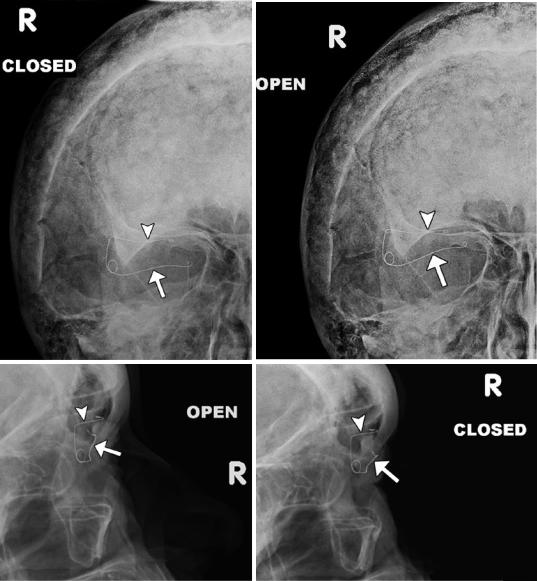
Palpebral springs may rarely be
used to treat patients with lagophthalmos secondary to facial nerve palsy. The device is implanted
a |
b |
c |
d |
via orbitotomy and consists of a palpebral branch and an orbital branch connected by a spring mechanism. The positioning and function of the device can be readily assessed on radiographs obtained in the open and closed lid positions, whereby the palpebral branch is expected to descend with lid closure (Fig. 2.2).
Fig.2.2 Eyelid spring. Open (a) and closed (b) lid frontal and open (c) and closed (d) lid lateral radiographs show the spring device to be well seated and functional. The palpebral branch (arrows) is noted to descend with respect to the orbital branch (arrowheads) during lid closure.
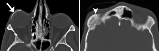
There are also stigmata of Paget’s disease in the skull. Axial CT images (e, f) in a different patient show the lower limb (arrow) of the spring properly positioned along the inner surface of the upper eyelid and the upper limb (arrowhead) implanted in the orbital roof
34 |
D.T. Ginat et al. |
|
|
e |
f |
Fig. 2.2 (continued)
2 Imaging the Postoperative Orbit |
35 |
|
|
2.3\ Frontalis Suspension Ptosis
Repair
2.3.1\ Discussion
Frontalis suspension may be used to elevate severely drooping eyelids in cases where the levator palpebrae superioris muscle is weak. In this procedure, autologous or alloplastic material
a
is used to create a subcutaneous attachment between the eyelid and the frontalis muscle. Expanded polytetrafluoroethylene (ePTFE) strips are visible on CT as hyperattenuating material configured as a sling in the upper eyelid (Fig. 2.3) in order to suspend the eyelid to the frontalis muscle. Potential complications include infection and granuloma formation.
b
Fig 2.3 Frontalis suspension ptosis repair. The patient is a child with a history of bilateral ptosis due to Marcus Gunn jaw-winking syndrome. Axial (a) and sagittal (b)
CT images show the hyperattenuating sling in the upper eyelids (arrows)
36 |
D.T. Ginat et al. |
|
|
2.4\ Orbital Wall Reconstruction
and Augmentation
2.4.1\ Discussion
Traditionally, autologous cartilage or bone (Fig. 2.4), silicone sheet implants (Fig. 2.5), and metal plates or mesh (Fig. 2.6) have been used for orbital wall fracture repair. More recent implant technology, including porous polyethylene materials (Fig. 2.7), has resulted in improved biocompatibility. The porous structure enables rapid ingrowth of vascular structures, soft tissues, and bone. Furthermore, endoscopic transantral approaches are increasingly used in order to
avoid eyelid incisions. Wedge implants can be used to augment orbital volume in patients with enophthalmos (Fig. 2.8). Transnasal wires can also be inserted to stabilize the medial canthus in trauma patients (Fig. 2.9). The role of imaging after orbital fracture repair is mainly to asses for complications, which may include infection, hematic cyst formation, implant deformity, and malpositioning, which may be accompanied by mucocele or nasolacrimal duct cyst formation due to obstruction and cerebrospinal fluid (Figs. 2.10, 2.11, 2.12, 2.13, 2.14, 2.15, 2.16, and 2.17). The leaks can be associated with compression of orbital contents, but can resolve spontaneously.
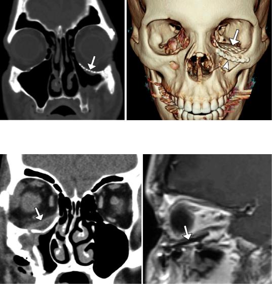
Fig. 2.4 Bone graft. Coronal CT image shows graft (arrow) harvested from the iliac bone used to reconstruct the left orbital floor (Courtesy of Gregory Katzman MD, MBA)
Fig. 2.5 Silicone implant. Coronal CT image shows left orbital floor fracture reconstruction with silicone implant (arrow)
2 Imaging the Postoperative Orbit |
37 |
|
|
a |
b |
Fig. 2.6 Titanium mesh. Coronal (a) and 3D CT (b) images show left orbital floor fracture repair with titanium mesh (arrow) and inferior orbital rim fracture with malleable titanium plate (arrowhead)
a |
b |
Fig.2.7 Porous polyethylene implant. Coronal CT image (a) shows the intermediate-attenuation sheet implant (arrow) positioned along the right orbital floor beneath the
inferior rectus muscle. The implant (arrow) appears as low signal intensity on the sagittal T1-weighted MRI (b)
38 |
D.T. Ginat et al. |
|
|
a
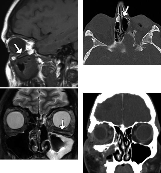
Fig. 2.9 Medial canthus stabilization. Axial CT image shows numerous healed left orbital fractures that involved the medial canthus, which is secured by a transnasal metal wire (arrow)
b
Fig. 2.8 Wedge implants. Sagittal T1-weighted (a) and coronal T2-weighted (b) MR images show the two lowintensity nearly parallel lines of the implant in the floor of the left orbit (arrows)
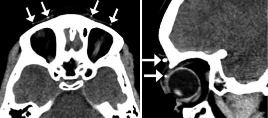
Fig. 2.10 Infection. Coronal post-contrast CT image shows diffuse right preand postseptal orbital cellulitis following recent medial and inferior orbital floor fracture repair with titanium mesh
2 Imaging the Postoperative Orbit |
39 |
|
|
Fig. 2.11 Hematic cyst. Coronal CT image shows a right inferior intraorbital lenticular-shaped fluid collection (arrow) along the surface of a silastic plate
Fig. 2.12 Mesh deformity. Coronal CT image shows deformity of the orbital floor titanium mesh implant (arrow)
a |
b |
Fig. 2.13 Inferiorly positioned mesh. The patient presented with enophthalmos after left inferior orbital wall repair with titanium mesh. Coronal (a) and sagittal (b) CT images show inferior displacement of the left orbital mesh (arrows)
40 |
D.T. Ginat et al. |
|
|
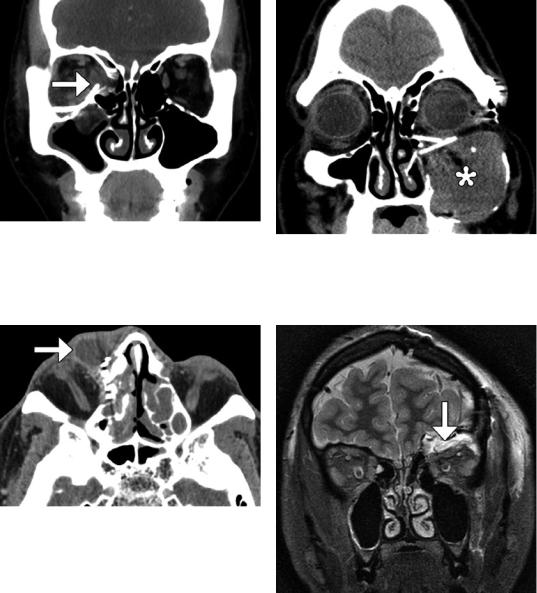
Fig. 2.14 Rectus muscle impingement. Coronal CT image shows lateral right medial orbital wall titanium mesh impinging upon the swollen medial rectus muscle (arrow). There is also persistent herniation of right orbital contents
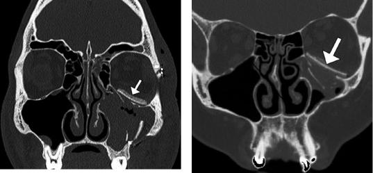
Fig. 2.15 Nasolacrimal duct obstruction. Axial CT image shows dilation of the right lacrimal sac (arrow) secondary to obstruction by titanium mesh
Fig. 2.16 Mucocele secondary to malpositioned implants. Coronal CT image shows an expansile left maxillary opacity (*) and obstruction of the infundibulum by the orbital floor reconstruction plates
Fig. 2.17 Cerebrospinal fluid leak. The patient underwent biopsy of a suspect orbital roof lesion with mesh reconstruction of the orbital roof. Coronal STIR MR image shows a fluid collection in the superior left orbit (arrow), with compression of the orbital contents