

DMC_Manual
.pdfDMC User manual |
Issue 1 |
|
|
Pan
The fader strips have a dedicated PAN/BAL logicator and this is sufficient for pan and balance when routing to normal stereo destinations.
The AFU has a Pan Panel with a Pan/Bal Logicator that duplicates the function of the channel Pan/Bal Logicator, plus Logicators for panning across additional destinations used by surround sound formats.
Pan and Balance
The PAN/BAL logicator is always in the signal path and will affect all normal stereo destinations the path is routed to.
Fig 50: Pan
logicator
The setting will be shown on the right hand side of the electronic scribble between the Logicators on the fader strip.
Surround Panning
When a path is routed to surround destinations (Tracks or Groups that have appropriate Pan Designators), then the panning controls must be enabled according to the surround format being used. If the correct panning controls are not switched on then the signal will be routed to the surround destination(s) with unity gain.
Stereo sources are not generally suitable for routing to surround destinations as panning may not affect the signal in the expected manner. It is advisable to listen to a stereo source as it is panned across the sound field to determine how it will behave before actually using it. Alternatively, feed the input into two separate mono paths and pan these independently (this may not be possible with M/S sources).
To enable LCR panning
Press the On/Off key associated with the Pan/Bal
Logicator.
The green led above the key will illuminate.
Fig 51: Pan panel
To enable Divergence
Press the On/Off key associated with the Divergence Logicator. The green led above the key will illuminate. Divergence controls the spread of the signal across the front destinations.
To enable panning from Front to Back
Press the On/Off key associated with the Front/Back Logicator. The green led above the key will illuminate.
To enable panning across the Rear surround
Press the On/Off key associated with the Rear L/R Logicator. The green led above the key will illuminate.
- 41 -

DMC User Manual |
Issue 1 |
|
|
Filters
The Filters Panel provides two low or high pass filters with a 3dB point between 12Hz and 20kHz.
Filters must be assigned to a path before they can be used.
Fig 52: Filter panel
The cut-off slope can be:
•FLAT
•6dB / Octave
•12dB / Octave
•18dB / Octave
•24dB / Octave.
If only one filter is assigned then the left hand set of filter controls will be active.
To activate a filter
Press the filter On/Off key. The green led above the key will illuminate.
To adjust the frequency
Make sure the SLOPE and HP/LP keys are off (integral leds unlit).
Turn the Logicator, and the exact frequency is shown in the AFU Parameter display.
To select high/low pass
Press the HP/LP key, and the integral led will illuminate red. Turn the Logicator. The HP/LP indicators will illuminate as selected.
To select the slope
Press the Slope key. The integral led will illuminate red. Turn the Logicator, and the slope values will illuminate to indicate selection. When none are illuminated the slope is flat.
- 42 -
DMC User manual |
Issue 1 |
|
|
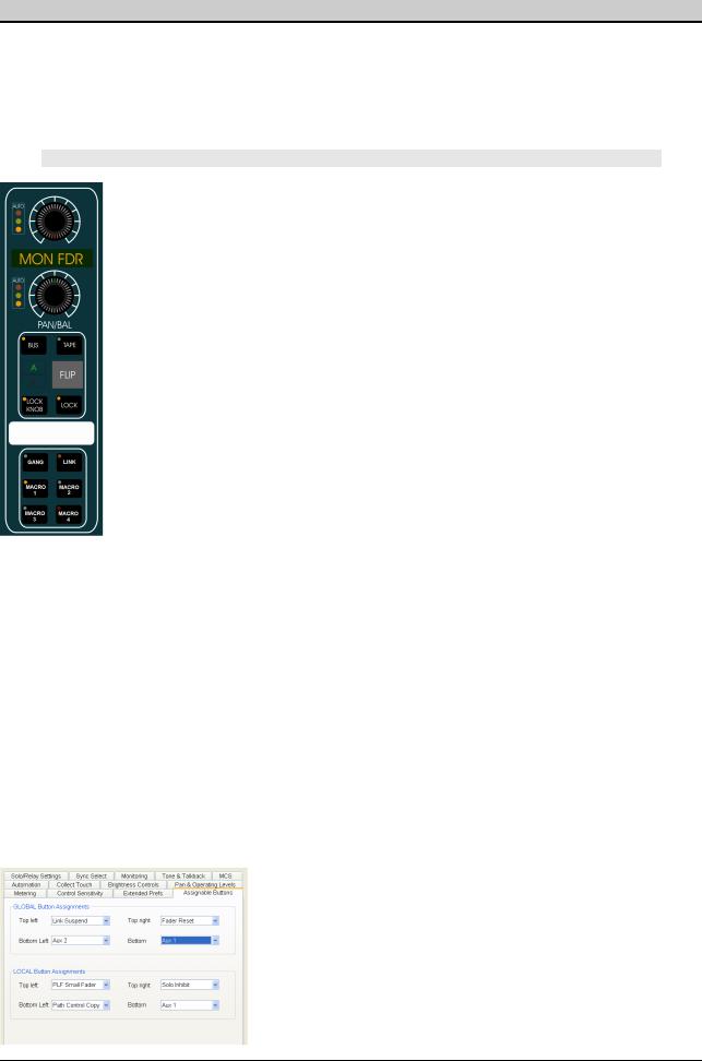
8 Assignable Logicator
The Assignable Logicator is the top Logicator on the fader panels.
It can be set to operate as a small fader, an Input or Output Track Trim control or it can be assigned to the function of any Logicator on the AFU.
The Assignable Logicator can also be locked to its current function on individual fader strips using the LOCK KNOB button.
STORE 1 / 2 / 3
These buttons on the Lower AFU provide 3 'snapshots' of console-wide logicator assignments. Press and hold the button, then touch the desired control on the AFU.
This assignment is now stored, and pressing this button will put that control on the logicators.
For example, you can set STORE 1 to be Aux 1 contribution level, STORE 2 to be compressor Gain and STORE 3 to be an EQ control. Once these have been set, pressing any of the STORE buttons will put that control on the logicators for paths currently held on the faders.
Using the Assignable Logicator as a Small Fader
Press the relevant BANK 1 - 6 and then use the FLIP button swap between faders & logicators.
The FLIP key will cause the assignment to switch between the fader and
Assignable Logicator.
Using the Assignable Logicator for AFU Functions
The Assignable Logicators can be set to duplicate the functionality of any
Logicator on the AFU.
Fig 53: Top of
Fader strip
To select an AFU function to the Assignable Logicator
Press and hold any of the Upper Knob Parameter STORE keys.
Touch the required Logicator on the AFU and release the STORE key.
The function name will appear in the electronic scribbles below the Assignable Logicators for paths assigned to the faders that have the selected processing element in the signal path. All the other electronic scribbles below the Assignable Logicators will be blank.
The function of the Assignable Logicator can be frozen on individual fader strips. Go to
Preferences/Extended Prefs and ensure the Upper Knob Lock box is checked.
Pressing the LOCK KNOB key on the fader strip will isolate the assignable logicator from global changes.
The integral led will illuminate red.
When the key is turned off, the Assignable Logicator will remain assigned to the same function until a new function is selected with a global key (e.g. STORE 2).
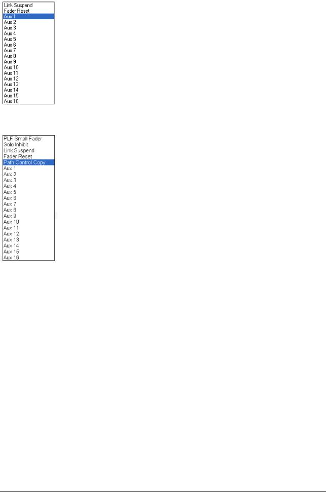
The MACRO 1 to MACRO 4 buttons allow you to set up 4 'soft' functions set in Encore System Preferences / Assignable Buttons which are then applied to the MACRO 1 - 4 buttons on the lower AFU and on each fader.
In this way, it is possible to have any 4 user-selected functions on the faders at any one time. Different functions can be assigned to the Global and Local buttons.
Fig 54: Prefs / Assignable Buttons
- 43 -
DMC User Manual |
Issue 1 |
|
|
GLOBAL BUTTONS
Link Suspend
Press and hold this button to change an offset between linked controls.
Fader Reset
Press and hold this button then touch the fader to reset it to 0dB.
Aux 1- 16
It is possible to assign the ON/OFF for any of the (up to) 16 auxes.
Fig 55: Global options
LOCAL BUTTONS
These have the same options as the Global buttons with the following additions:
PFL Small Fader
Operates as a PFL button for the path held on the small fader.
Solo Inhibit
Keeps the path open when a Solo is detected somewhere on the console.
Suitable for example, for hearing vocals in context with it's reverb returns.
Path Control Copy
Puts the desk into Copy mode and allows you to set up a copy template, and then copy this collection of control values between paths.
Fig 56: Local options
- 44 -
DMC User manual |
Issue 1 |
|
|
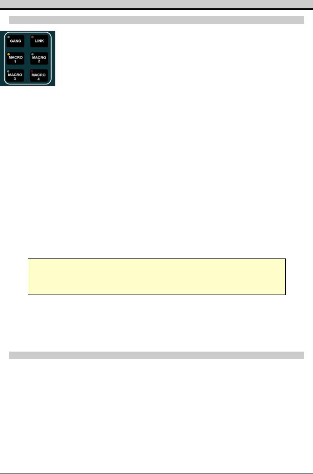
9 Gangs & Links
Gangs
Fig 57: Gang/Link buttons
A Gang hierarchy has a Master and at least one Slave, though usually there are multiple Slaves.
There can be an offset between the Slaves, and/or between any of the Slaves and the Master.
•Moving the Master means all of the Slaves move as well, retaining any offsets.
•Moving a Slave means just the offset between that Slave and it's Master is changed.
It is only possible to Gang Faders and Cuts.
To Create a Gang
Press the GANG button on the fader you wish to be Master.
The console will go into Gang mode and flash the word GANGING across all the fader alphas displays.
Press the Access keys for the faders you wish to be Slaves. As you press the first Access key, the MST led will light by the fader on the Master, and the SLV led will light by the Slave fader.
Further SLV leds will light for every fader added into this Gang. To terminate Gang mode, press the Master's GANG button again.
Repeat the above process in reverse to remove a Gang setup.
It is only possible to nest Gangs up to 2 levels (ie a Slave fader can also be a Master to a sub-Gang).
With regard to writing automation data, 'hard' data is only written for the Master. All the Slave automation is 'soft' written, ie in the form of an offset with regard to the Master.
For this reason, when removing a gang, it is advisable to Coalesce it first. Coalescing means the Automation engine looks at the Master automation, takes into account the Slaves offset from this, and hard-writes this data for the Slave(s). Coalescing a gang will create a new Mix/Pass if you are logged onto Automation.
With Gangs, it is possible to add Slaves 'on the fly' to any Gang after starting an automation pass.
For more information, see the chapter on the GANGS Menu in the Encore Plus manual.
Links
A Link has no Master/Slave relationships in place.
Instead, moving any control in a link will also move the same control for other members. Any offsets in place will be respected and retained.
With regard to writing automation data, 'hard' data is written for all members in the link. For example, move a fader and it's associated automation led will flash, as will those for all the other faders in the link even though they have not been touched.
It is possible to link all controls apart from Mic Gain, Porting and Delay.
- 45 -

DMC User Manual |
Issue 1 |
|
|
To Create a Link
Press the LINK button on a any path you wish to include in the link.
The console will go into Link mode and flash the word LINKING across all the fader alphas displays.
That path will be called to the AFU, and all available controls will be lit red, indicating the current set of controls that can be linked. If you only wish to link the Pan and Aux 1, then touch the Pan (it will remain lit red, but all other controls will be dropped from the Link scope), and touch Aux 1.
Only these two controls are now lit red.
The CUT MODE and FDR MODE buttons by the fader will also be lit red.
Press these buttons to drop the FADER and the CUT from the scope of controls to be linked.
Once you have set the scope of controls to be linked, press other Access keys to add those into the Link.
A control can only be included in one link at a time.
When you go into Link mode, any previous Links that have been set up will be indicated by those paths Access key lighting.
•To change the offsets between faders in a Link, hold and fader, then move the fader you wish to change the offset of, then release both faders.
•To change the offsets between other controls in a Link, you will need to apply the LINK SUSPEND option to one of the 4 local Macro buttons. Press this button on the path you wish to change a controls offset on before changing the control itself.
Each time you enter LINK mode, the scope for all controls to be linked will be reset to include all controls, so it may be necessary to amend the scope for each Link you wish to create.
- 46 -

DMC User manual |
Issue 1 |
|
|
10 Routing & Porting
There are two types of routing on the console:
•I/O Routing for connecting physical input and output ports to the appropriate signal paths. These connections involve a path to the outside world.
•Path Routing for connecting signal paths together to form a clear path from input to output. All of this takes place internally to the console.
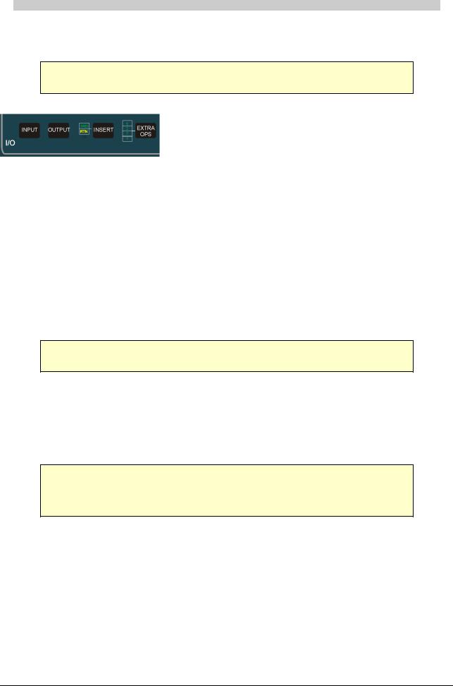
I/O Routing
I/O Routing can be controlled with I/O Patching in Encore or from the I/O Panel on the AFU.
This chapter describes Input/Output Routing with the AFU I/O Panel and Interrogating I/O Routing.
See the Tools Menu chapter in the Encore Plus manual for information on I/O Patching.
Fig 58: I/O Panel
Path Routing
Path Routing can only be controlled from the console surface. This is done using the Routing Screen with its associated keys and/or the Access Keys on the Fader panels.
Legal routing combinations are as follows:
Channels to: |
Tracks, Groups, Main Outputs and Auxiliaries |
Tracks to: |
Tracks, Groups, Main Outputs and Auxiliaries |
Groups to: |
Tracks, Main Outputs and Auxiliaries |
Main Outputs to: |
Cues |
Auxiliaries to: |
Cues |
|
Table 3: Valid Routing |
This does not include selections made in the monitoring system (monitoring, talkback, tone, etc).
The routing software ensures that no feedback loops will occur (e.g. Setting up a 'circular' route such as TK 1 to GRP1, GRP1 to TK 2 and then TK 2 to TK 1).
Whichever step is attempted last in making such a routing pattern is simply ignored, and a warning message will be shown on the fader alpha displays:
“Circular route attempted, disallowed”
- 47 -
DMC User Manual |
Issue 1 |
|
|
I/O Porting with the Upper AFU I/O Panel
The I/O Panel allows the currently accessed path to be port routed to an input, an output and any inserts that have been allocated.
If a Main Output path has a 2nd output assigned to it then this must be port routed with I/O Patching or Path Edit.
To select an input or output
Press the Input or Output key on the I/O Panel.
The integral led in the key will illuminate.
The alpha display to the right of the selector Logicator will show the current path and the port type (e.g. CH6 IN or TK22 OUT).
If necessary, press the On/Off key to de-route the currently selected port.
The green led above the key will be extinguished.
To change the I/O Bank
Press the double arrow key.
The integral led will be illuminated for Bank selection.
Rotate the selection Logicator to the right of the double arrow key.
The Banks will change in the alpha display to the right of the double arrow key. Examples of Input Banks are 1lin (1st I/O rack, mic/line ports) and 2aes (2nd I/O rack, AES/EBU ports).
Examples of Output Banks are 1LIN and 3MAD.
Input ports are shown on the console and in Encore in lower case.
Output ports are shown on the console and in Encore in UPPER CASE.
To change the Port on the selected Bank
Press the double arrow key. The integral led will not be illuminated for Port selection.
Rotate the selection Logicator to the right of the double arrow key.
The port numbers will change in the alpha display.
If a Bank or Port does not physically exist then the green indicator led in the top of the selector Logicator will not illuminate. This is most likely to happen on unused MADI ports. This also happens if the port type does not exist on the current path (e.g. Mains do not have input ports).
To switch on the selected port
Press the On/Off key.
The green led above the key will illuminate if the port allocation is successful.
To select Inserts port routing
Press the INSERT key. The integral led will illuminate.
The alpha display to the right of the selector Logicator will show the current path and the insert number (e.g. CH6 INS1).
When the Insert key is active, the Input and Output keys select between the insert Send and Return.
These are port routed in the same way as normal inputs and outputs and the Snd and Rtn indicators illuminate to show successful port routing.
- 48 -

DMC User manual |
Issue 1 |
|
|
Press the INSERT key again for the second insert. The alpha display to the right will change accordingly (e.g. CH6 INS2).
Press the Insert key again for normal port routing, and the integral led will cease to be illuminated.
If an insert does not exist in the currently accessed path then the green indicator led in the selector Logicator will not illuminate.
The inserts are half-normalled, so it is possible to use an insert send as a direct output whose pick-off point can be moved to anywhere in the signal path.
You can achieve this by only porting the Send and leaving the Return unported. Once the Return is ported, then the path will take it’s signal from this port, rather than from the signal path itself.
Inserts must first be assigned using Desk Editor or Path Edit in Encore.
To select Mic or Line inputs
This is only applicable to lin banks (e.g. 1lin, 2lin, etc.).
Press the Mic or Line key as required.
The green led above the selected key will illuminate.
The Analogue Gain logicator can be used to change the input level before conversion to a digital signal (-75dBu to +14dBu).
To activate Phantom power
Press the 48V key on a lin input that is switched to Mic, and the green led above the 48V key will illuminate.
Phantom power is applied to both A and B mic input lines.
To change the Input Phase
Press the Phase Rev key.
If the input is MONO:
•The green led above the key will illuminate. Press Phase Rev again to return the path to it’s normal state.
If the input is STEREO:
•The green led above the key will illuminate and the Left indicator adjacent to the key will illuminate. The phase indicator adjacent to the fader will light.
•Press the Phase Rev key again to reverse the phase on the Right leg of a stereo input.
•Press the Phase Rev key again to reverse the phase on both legs of a stereo input (the Left and Right indicators will illuminate as appropriate).
•Press the key again to turn phase reversal off.
To switch a stereo input between AB and MS
Ensure the process has been added in either Desk Edit or Path Edit.
Press the AB/MS key.
The input will toggle between AB and MS decoding.
The indicators next to the key will show the selection.
To trim the input or output level
Where applicable (for example on Tracks which has both an Input and an Output Trim), press either the INPUT or OUTPUT button by the porting logicator so the correct Trim is applied.
- 49 -

DMC User Manual |
Issue 1 |
|
|
Adjust the TRIM Logicator as required.
+/- 24dB of trim is available.
To change the width of the stereo image
Adjust the WIDTH Logicator as required.
The input or output must be selected as a wide stereo signal in Desk Edit or Path Edit.
To adjust delay on a port
Adjust the DELAY Logicator as required.
Delay must have been assigned to the port in the I/O Configuration.
- 50 -