

DMC_Manual
.pdfDMC User manual |
Issue 1 |
|
|
Fig 29: Fuel Gauges
Click the tabs for the Channels and Tracks to see the default processing that has been allocated.
Notice that two 'processing meters' appears in the title bar when you change to a different page.
These Fuel Gauges show how much processing will be used by the new Desk Setup, as a percentage of the total available.
Fig 30: Surround Designators
Also, on the Tracks tab, each path has a blue square at the bottom of each path. This indicates the Pan Designator for each path.
The selected film format is 5.1, so the Pan Designators have been automatically applied to the Tracks to match the film format.
The only other step that is necessary for a working Desk Setup is to decide which paths are assigned to which fader strips. This is accomplished with the Desk Designer.
A Desk Setup can be saved without assigning any paths to the console surface, but if you do so, then you will be prompted that no paths have been assigned and whether you want to continue.
Desk Designer is used to decide which signal paths are assigned to which fader strips. Each fader strip can have two signal paths assigned on each Bank, which can be swapped between the fader and assignable logicator using the Master FLIP button on the lower AFU or the local FLIP button by the fader.
For this exercise, you are going to assign Channels to the Faders and Tracks to the Assignable Logicators.
Open Desk Editor click the Desk Designer tab.
Fig 31: Desk Designer
•Click the Faders check box so that a tick is shown.
•Click the first path in the path list (Channel 1).
•Scroll the path list down until path 12 (i.e. Channel 12) is shown.
•Hold down the Shift key on the keyboard and click Channel 12, so the first 12 Channels will be highlighted.
•Click the Assign button.
The Channel numbers will be displayed in the boxes just above the faders .
The Desk Setup is now functional because there are some paths assigned to the fader strips. However, it would be useful to assign the Tracks to the Knobs.
To assign Tracks to the Knobs
•Remove the tick from Faders and tick the box for Knobs.
•Click the Tracks radio button (the paths list will change to show the Tracks).
•Click TRK1 in the paths list, scroll down the list to TR12, hold down Shift on the Keyboard and click TR12.
•Click the Assign button.
The Track names will be displayed in the boxes above the faders corresponding to the Assignable logicators.
To Automatically configure the Film Stems
There are six Film Stems that are labelled A to F. They are constructed by assigning Tracks in groups to each Stem letter.
- 21 -
DMC User Manual |
Issue 1 |
|
|
In this Desk Setup we have 12 Tracks. The film format is 5.1 which uses six speaker positions. A fully configured 5.1 Stem will use 6 Tracks, one for each speaker position. Each Track already has a suitable pan designator according to the intended speaker destination.
To configure the Film Stems automatically, click the Stems tab.
Fig 32: Stem Assignments
Click the Automatic button.
A warning dialogue box will be displayed, indicating that all Stems will be reconfigured.
Click Yes.
The Tracks will be assigned to Stems A and B (i.e. six each).
Notice that the Track names in the Paths list are shown in green when they are allocated to a Stem.
Each Track will also be routed to the Film path that corresponds to its pan designator. For instance, Track 2 has the Front Centre pan designator so it is routed to Film 2 (which should be, in turn, port routed to the output connected to the front centre speaker).
The Desk Setup is now complete and ready to be saved.
•Click Save & Load.
A dialogue box will appear asking for confirmation of creating the new setup. Click the Yes button or press Y on the keyboard.
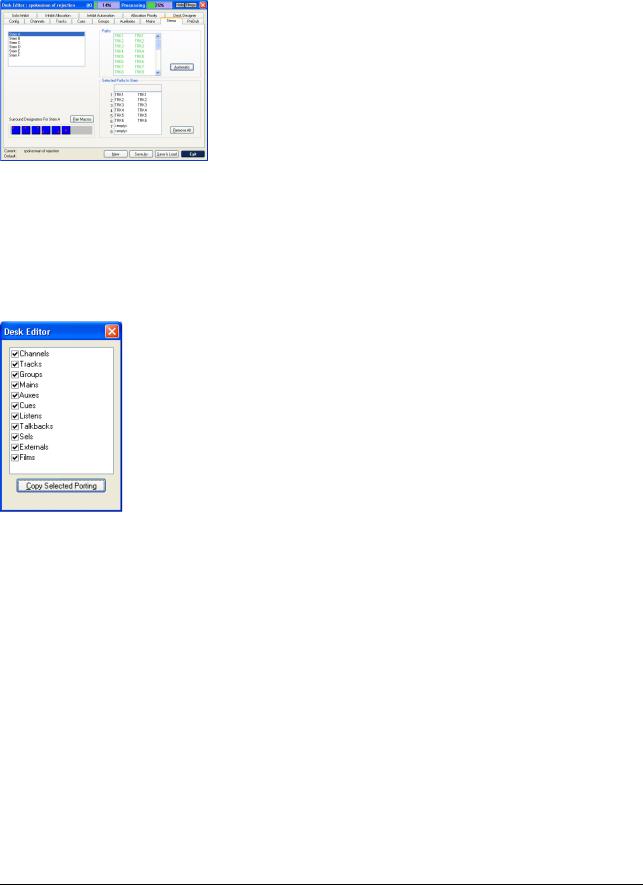
Fig 33: Copy Porting
A second dialogue box will be displayed for selecting the porting information to be copied to the new Desk Setup. It is not necessary to deselect any of the check boxes.
Click the Copy Selected Porting button.
The screen will display a timer to show the Desk Setup is being saved, followed by a second timer while the setup is applied to the console surface. The electronic scribble strips on the console surface will also indicate the progress of the allocation.
When allocation is complete, a dialogue box will be displayed to indicate this.
Click OK or allow the dialogue box to close automatically, or Click the Exit button to finish using Desk Edit.
To Select the Channel Input
Press the Access key for Channel 1, and the path will be called to the AFU. Part of the AFU is the I/O Panel which is used for port selection.
•Press the INPUT key. The integral will illuminate.
•Press the double-arrow key next to the selection Logicator.
The selection Logicator can now be used to select the rack number and port type. Rotate the selection Logicator to the appropriate rack number/port type.
•Press the double-arrow key again.
The integral led will cease to be illuminated and the selection Logicator can now be used to select the actual port. Rotate the selection Logicator to the appropriate port number.
•Press the On/Off key to turn the port on, and the port will be assigned to the input of Channel 1.
To Route Channel 1 to Stem A
To route Channel 1 to the Tracks for Stem A.
•Press the SURR MON button so the led above it is lit.
•Press and hold the Access key for Input 1.
- 22 -

DMC User manual |
Issue 1 |
|
|
•Press the A button above the routing screen. The internal leds on the first six Track keys at the top of the Routing Screen will turn red.
The panning controls are enabled automatically in Channel 1, according to which pan designators are applied to the Tracks that Channel 1 is routed to.
To Monitor Stem A
Make sure the SUM key is off (press it if the led above the key is illuminated).
•Ensure that ALL BUS and SURR MON are lit.
•Press the A key.
The led above the key will illuminate.
To confirm the signal is routed correctly.
•Put the device for the signal source into Play.
•Gradually increase the level on the fader for Channel 1 and the Control Room level control until audio is heard on the control room speakers.
•Adjust the panning controls on the AFU to confirm that panning is operating.
- 23 -

DMC User Manual |
Issue 1 |
|
|
What To Try Next
The console is quick and easy to get started and offers high levels of flexibility and power.
The following topics explore some of the basic functions of the console:
•Layer Selection on the Fader Strips
•Assigning Paths to Different Fader Strips
•Assigning EQ to a Channel
The Lock keys on the fader strips used to control which fader strips will be affected by the BANK keys and Master FLIP.
To Swap path assignments between the fader and the Assignable Logicators
•Press the FLIP key on the required fader strip, or press the Master FLIP key to swap
all faders.
If the Assignable Logicator is assigned to the same path as the fader then the Flip key will have no effect.
To prevent the BANK 1 - 6 or FLIP keys from re-assigning individual faders, press the LOCK key on the required fader strips. The integral led will illuminate.
To prevent the Bank 1 - 6 or FLIP keys from re-assigning individual small faders, press the LOCK KNOB key on the required fader strips. The integral led will illuminate.
As well as locking the current path to the Small Fader, the current function of the Assignable Logicator is also locked (you must ensure that the Upper Knob Lock box is checked in
Preferences/Extended Prefs).
Saving the console setup
The current console setup may be saved to hard disk by pressing and holding the ALL/SCOPE button, and pressing KEEP MIX on the Utility panel.
- 24 -

DMC User manual |
Issue 1 |
|
|
4 Working with Signal Paths
Path is the term used to describe a discrete part of the signal flow through the console that has a distinct input and output, either to the outside world or to another path.
A port is an interface to the outside world, e.g. a D to A output converter, an AES/EBU input or a digital MADI input or output.
Note that all path types can make use of any signal processing functions, including using up to two inserts each. The total amount of processing available depends on the hardware configuration.
The types of signal paths used by the console are:
•Channels
•Tracks
•Main Outputs
•Groups
•Auxiliaries
•Cues
•Externals
•Predubs
•Films
•System Paths
Each is described in the following chapters.
Channels
Channels provide the main inputs to the console. They can be mono or stereo.
The default path names for Channels are just the number for the path (e.g. 1, 23, etc.).
Channels must be connected (port routed, patched) to an Input Port.
This is achieved using I/O Patching or the I/O Panel on the AFU.
Mic/Line switching is provided on the Fader Strips and the I/O Panel, with input gain and trim control on the I/O Panel.
A Channel can also have a direct output assigned to it.
Channels can be routed to Tracks, Main Outputs and Groups. They can also make contributions to Auxiliaries.
Channels are where most of the initial signal processing is applied.
- 25 -
DMC User Manual |
Issue 1 |
|
|
Tracks
The Tracks provide the same functionality as tape monitors and track sends on conventional analogue consoles.
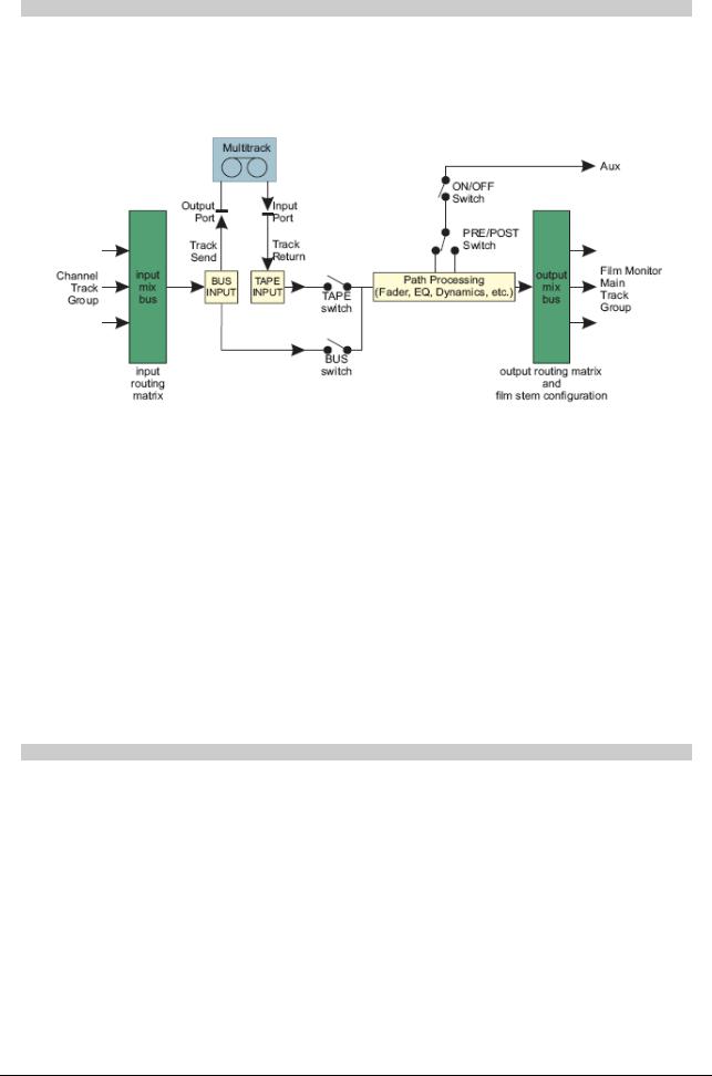
Tracks can be switched between Bus and Tape inputs, as shown on the Track Signal Path Schematic.
Fig 34: Tracks Schematic
They can only be mono.
The default path names are TRK1 to TR32.
Tracks have a track send (output) and track return (input) at the beginning of the signal path. These can be connected (port routed, patched) to an Output and an Input Port. This is achieved using I/O Patching or the I/O Panel on the AFU. Bus/Tape switching is provided on the Fader Strips and with global ALL BUS and ALL TAPE switching in the Surround Monitor section.
Tracks can have Channels, Groups and other Tracks as routing sources. They can be routed to Main Outputs, Groups, Auxiliaries and other Tracks. The software that controls routing prevents any feedback loops from occurring.
Tracks can be used as surround sound destinations and this is setup using the Pan Designators and Pan Macros functions in Desk Edit.
Tracks are also used as Stem Busses.
Main Outputs
Main Outputs (or Mains) are the primary destination for final mixes and overall console output.
Mains are also the most commonly selected source for control room monitoring.
They can be mono, stereo or stereo wide. There can be up to four Mains in a Desk Setup.
Mains can be assigned to fader strips just like any other path.
The default path names are MAI1 to MAI4.
Mains can have one or two outputs at the end of the signal path. These can be connected (port routed, patched) to Output Ports using I/O Patching or the I/O Panel on the AFU.
Mains can have Channels, Groups and Tracks as routing sources. They can be routed to Cues or used as monitoring sources.
- 26 -

DMC User manual |
Issue 1 |
|
|
Groups
Groups provide extra mix busses and pre-mixes for routing to Main Outputs or track sends. Groups can be mono or stereo.
There can be up to 24 Groups in a Desk Setup, and their default path names are GRP1 to
GR24.
Groups can have one output at the end of the signal path that can be connected (port routed, patched) to an Output Port. This is achieved using I/O Patching or the I/O Panel on the AFU.
Groups can have Channels and Tracks as routing sources. They can be routed to Main Outputs and Tracks.
The software that controls routing prevents any feedback loops from occurring.
They can also make contributions to Auxiliaries.
Mono Groups can also have pan designators applied and this is setup using the Pan Designators and Pan Macros functions in Desk Edit.
Any Channels routed to them will pan to the Group according to the designated pan position. This would be useful, for instance, in feeding an out-board effects unit with the panned signal(s) for the rear surround, which could then be looped back into the console via an input to a Channel.
Groups are not used in Film Stems, as they cannot use Bus/Tape switching .
Auxiliaries
Auxiliaries provide additional mix busses for creating cue mixes and extra output mixes. There can be up to 16 Auxiliaries in a Desk Setup, any of which can be mono or stereo (a stereo aux is intrinsically stereo and does not 'steal' the next available aux for the other leg).
Auxiliary master faders can be assigned to fader strips.
The default path names are AUX1 to AU16.
Auxes can have one output at the end of the signal path that can be connected (port routed, patched) to an Output Port. This is achieved using I/O Patching or the I/O Panel on the AFU.
Auxes can take pre and post fader contributions from Channels, Groups and Tracks. They can also be routed
to Cues.
Fig 35: Aux Panel
To select an aux to contribute to
Press the Access key for the path to route to the aux, and the selected path will be assigned to the AFU. Press the required On/Off key on the AUX Panel. The green led above the key will illuminate.
To switch banks between auxes 1-8 and 9-16, press the BANK key. The number indicators next to the Logicators will illuminate to show the auxes that are available.
To switch between pre and post fader pick off, press the Pre/Post button.
The Pre/Post indicators will illuminate to show the selection.
To switch the Logicator to pan/balance (this is only possible if the aux is stereo).
Press the PAN/BAL key for the required aux contribution, and the integral led will illuminate red. Turn the Logicator. The Pan/Bal position is indicated in the Left/Right bargraph display above the Pan/Bal key.
- 27 -

DMC User Manual |
Issue 1 |
|
|
To use the Assignable Logicators on the fader strips for aux contributions
Press and hold down one of the STORE (1, 2 or 3) keys on the AFU Fader strip. Touch the Logicator for the desired Aux on the AFU.
The selected aux will appear in the alpha displays below the assignable Logicators. Aux contributions that are turned down to a sufficiently low level will be switched off automatically.
To use the Faders for Aux Contributions
Also known as ALL AUX mode.
Ensure that the relevant Master Aux Send is on the console surface somewhere. Press and hold it's Access key, then touch the fader itself. The console will go into ALL AUX mode. The strip displays will alternate between the names of paths on the surface and the Aux selected (e.g. AU 2).
Repeat these touches to terminate the All Aux function.
The paths that are on the surface can be changed as normal so that different paths can be selected for aux contributions (see Layer Selection on the Fader Strips).
Cues
Cues are typically used to feed the headphones or studio loudspeakers.
There can be up to twelve mono or stereo Cues in a Desk Setup (Cues default to stereo).
Cues can be assigned to the console surface, although this is not necessary for their operation.
The default path names are CUE1 to CU12.
Cues can use Auxiliaries and Mains as routing sources. Cues are normally output via the monitoring system (to the control room, headphones, etc.), but can also be I/O routed to output ports (with I/O Patching or Input/Output Routing with the AFU I/O Panel) which could also have speakers attached.
Externals
Externals are used to provide additional direct inputs to the Monitoring System.
Each External machine can either be stereo (maximum number of 16) or surround (3 machines up to 24 inputs wide). The number of inputs from each external device is specified as part of the Desk Setup in the Config page of Desk Edit.
The default path names for Externals are EXT1 to EX88, etc.
Externals can be assigned to the console surface, although this is not necessary for their operation.
Externals must be connected (port routed, patched) to an Input Port. This is achieved using
I/O Patching.
The Externals are selected for monitoring using the Monitor Select section of the lower AFU.
- 28 -

DMC User manual |
Issue 1 |
|
|
Predubs
The console allows up to 48 predubs of linked input paths to be defined. A Predub is then assigned to one fader strip to conserve space.
A predub can be expanded across adjoining faders for adjusting fader offsets etc.
PreDub Masters
PreDub Masters are a control only path type used to control the predub members (consisting of any combination of mono Channels or Tracks. It is not possible to use stereo Channels in a predub).
•PreDub Masters uses no processing resources.
•All controls in the predub members are linked to the PreDub Master.
PreDub Masters are assigned to the surface using the Desk Designer page of Desk Edit. If a PreDub Master is not assigned to the surface then it is not possible to expand it and access the member paths.
PreDub Masters can control a group of up to 8 Channels and/or Tracks.
The predub members are 'stacked' under the PreDub Master and are accessed individually by expanding the predub across the PreDub Zone. A predub can not be expanded if the console does not have a PreDub Zone.
The PreDub Zone
The PreDub Zone is a block of (up to) eight contiguous channels which is used for expanding predubs.
The location and width of the PreDub Zone is set using System Preferences / Extended Prefs. Individual predubs are at least 2 faders wide, and no more than 8.
To expand a predub
Hold the Access key for the Predub Master and press the Master FLIP or local FLIP button. The associated alphas will display the user name for the predub.
If a Predub has been expanded, it can be collapsed again by repeating the above button presses, or pressing the Master FLIP button. This will reapply part of the current layer over the Predub Slaves.
The paths in the predub will be expanded across the predub zone, and each path can now be controlled in the same way as a normal path. The PreDub Master will remain in place and changing its controls will change the ‘slaved’ controls in the predub zone.
•Continuous controls (faders, EQ frequencies, etc.) can be moved to change the offset from the PreDub Master and the offset is retained.
•Stepped controls (phase reverse, aux pre/post, etc.) can be changed, but if the PreDub Master is changed then the predub members will follow the Master settings.
To collapse the Predub again, repeat the same button presses as used to expand it.
- 29 -

DMC User Manual |
Issue 1 |
|
|
PreDub Cuts and Solos
A Cut or Solo on a PreDub Master will Cut or Solo all the paths in the PreDub.
• While a PreDub Master Cut or Solo is on, the individual Cut or Solo on a PreDub member can be switched on or off, but will not override the Cut or Solo imposed by the Master.
• The individual Cut or Solo on a PreDub member only takes effect when the Cut or Solo for the PreDub Master is off.
• An individual Cut or Solo on a PreDub member will remain on, even when Cut or Solo on the PreDub Master is turned off.
Fig 36: Predub Cut/Solo
PreDubs in Gangs
A PreDub Master can be selected as a Gang Sub-Master, but are automatically only a SubMaster to the paths in the PreDub.
They cannot be a Sub-Master of other paths. The PreDub members are Slaves to the PreDub Master only.
When the Gang Master or Sub-Master is moved, the PreDub page is used to assign up to eight Channels or Tracks to a predub master.
Up to 48 predubs may be defined. PreDub Master paths are created with the default system names of PM1 to PM48.
PreDub Masters use no processing resources!
To Assign Paths to a Predub
Open Desk Editor and click the Predubs tab.
Click a predub in the predubs list, and then set the width of the predub using the PreDub Zone Width box (between 2 and 8).
Click the Channels or Tracks radio button. Drag and drop each required path from this list to the Selected Paths in PreDub list (the names of paths used in predubs will turn green).
Fig 37: Desk Editor / Predubs
If a path which is already assigned to a predub is dragged and dropped, a dialogue box will appear to confirm whether or not the path should be moved from one predub to the other.
Fig 38: Predub confirm
The PreDub Zone Width column in the predubs list will show the number of paths in the predub.
- 30 -