

reading / British practice / Vol D - 1990 (ocr) ELECTRICAL SYSTEM & EQUIPMENT
.pdfPower system performance analysis
|
|
|
|
|
|
|
|
|
|
|
|
|
|
|
|
|
|
|
|
|
|
|
|
|
|
|
|
|
|
|
|
|
|
|
|
|
|
|
|
|
|
|
|
|
|
|
|
|
|
|
|
|
|
|
|
|
|
|
|
|
|
|
|
|
|
|
|
|
|
|
|
|
|
|
|
|
|
|
|
|
|
|
|
|
|
|
|
|
|
|||||||||
NETWORK DRAWING AND MODIFYING ROUTINE |
|
|
|
|
|
|
|
|
|
|
|
|
|
|
|
|
|
|
|
|
|
|
|
|
|
|
|
|
|
|
|
|
|
|
|
|
|
|
|
|
|
|
|
|
|
|
|
|
|
|
|
|||||||||||||||||||||||||||||||||||||||||||||||
<SUBSYSTEM NO. I> Gi |
|
|
|
|
|
|
|
|
|
|
|
|
|
|
|
|
|
|
|
|
|
|
|
|
|
|
|
|
|
|
|
|
|
|
|
|
|
|
|
|
|
|
|
|
|
|
|
|
|
|
|
|
|
|
|
|
|
|
|
|
|
|
|
|
|
|
|
|
|
|
|
|
||||||||||||||||||||||||||
|
|
|
|
|
|
|
|
|
|
|
|
|
|
|
|
|
|
|
|
|
|
|
|
|
|
|
|
|
|
|
|
|
|
|
|
|
|
|
|
|
|
|
|
|
|
|
|
|
|
|
|
|
|
|
|
|
|
|
|
|
|
|
|
|
|
|
|
|||||||||||||||||||||||||||||||
|
|
117 |
|
213 |
|
|
|
|
|
|
|
|
|
|
|
|
|
|
|
|
|
|
|
|
|
|
|
|
|
|
|
|
|
|
|
|
|
|
|
|
|
|
|
|
|
|
|
|
|
|
|
|
|
|
|
|
|
|
|
|
|
|
|
|
|
|||||||||||||||||||||||||||||||||
|
|
|
|
|
|
|
|
|
|
111 |
|
|
|
|
|
|
|
|
|
|
|
|
|
|
|
|
|
|
|
|
|
|
|
|
|
|
|
|
|
|
|
|
|
|
|
|
|
|
|
|
|
|
|
|
|
|
|
|
||||||||||||||||||||||||||||||||||||||||
|
|
|
|
|
|
|
|
|
|
|
|
|
|
|
|
|
|
|
|
|
|
|
|
|
|
|
|
|
|
|
|
|
|
|
|
|
|
|
|
|
|
|
|
|
|
|
|
|
|
|
|
|
|
|
|
|
|
|
|
|
|
|
|
|
||||||||||||||||||||||||||||||||||
|
|
|
|
|
|
|
|
|
|
|
|
|
|
|
|
|
|
|
|
|
|
|
|
|
|
|
|
|
|
|
|
|
|
|
|
|
|
|
|
|
|
|
|
|
|
|
|
|
|
|
|
|
|
|
|
|
|
|
|
|
|
|
|
|
|
|
|
|
|
|
|
|
|
|
|
|
|
|
|
|
|
|
|
|
|
|
|
|
|
|
|
|||||||
|
|
|
|
|
|
|
|
|
|
|
|
|
|
|
|
|
|
|
|
e |
|
|
1 Ito |
|
|
|
|
|
|
|
|
|
|
|
|
|
|
|
|
|
|
|
|
|
|
|
|
|
|
|
|
|
|
|
|
|
|
|
|
|
|
|
|
|
|
|
|
|
|
|
|
|
|
|
|
|
|
|
|
|
|
|
|
|
|
|
|
|
|
|
|
|||||||
|
|
|
|
|
|
|
|
|
|
|
|
|
|
|
|
|
|
|
|
|
|
|
|
|
|
|
|
|
|
|
|
|
|
|
|
|
|
|
|
|
|
|
|
|
|
|
|
|
|
|
|
|
|
|
|
|
|
|
|
|
|
|
|
|
|
|
|
|
|
|
|
|
|
|
|
|
|
|
|
|
||||||||||||||||||
|
|
|
|
|
|
|
|
|
|
|
|
|
|
|
|
|
|
|
|
|
|
|
|
|
|
|
|
I |
|
|
|
|
|
|
|
|
|
|
|
|
|
|
|
|
|
|
|
|
|
|
|
|
|
|
|
|
|
|
|
|
|
|
|
|
|
|
|
|
|
|
|
|
|
|
|
|
|
|
|
|||||||||||||||||||
|
|
|
|
|
|
|
|
|
|
|
|
|
|
|
|
|
|
|
|
|
|
|
|
|
|
|
|
|
|
|
|
|
|
|
1129 |
|
|
|
|
WI |
|
|
|
|
|
|
|
|
|
|
|
|
|
|
|
|
|
|
|
|
|
|
|
|
|
|
|
|
|
|||||||||||||||||||||||||||||
|
|
|
|
|
|
|
|
|
|
|
|
|
|
|
|
|
|
|
|
|
|
|
|
|
|
|
|
|
|
|
|
|
|
|
|
|
|
|
|
|
|
|
|
|
|
|
|
|
|
|
|
|
|
|
|
|
|
|
|
|
|
|
|
|
|
|
|
|
|
|
|
|
|
|
||||||||||||||||||||||||
|
|
|
|
|
|
|
|
|
|
|
|
|
|
|
|
|
|
|
|
|
|
|
|
|
|
|
|
|
|
|
|
|
|
|
|
|
|
|
|
|
|
|
|
|
|
|
|
|
|
|
|
|
|
|
|
|
|
|
|
|
|
|
|
|
|
|
|
|
|
|
|
|
|
|
|
|
|
|
|
|
|
|
|
|
|
|
|
|
|
|
|
|
|
|
|
|||
|
|
|
|
|
|
|
|
|
|
|
|
|
|
|
|
|
|
|
|
|
|
|
|
|
|
|
|
|
|
|
|
|
|
|
|
|
|
|
|
|
|
|
|
so |
(2) |
|
|
|
|
|
|
|
|
|
|
|
|
|
|
|
|
|
|
|
|
|
|
|
|
|
|
|
|
|
|
|
|
|
|
|
|
|
|
|
|
|
|
|
|
|||||||||
|
|
|
|
|
|
|
|
|
|
|
|
|
|
|
|
|
|
|
|
|
|
|
|
|
|
|
|
|
|
|
|
|
|
|
|
|
|
|
|
|
|
|
|
|
|
|
|
(13) X |
|
|
|
|
|
|
|
|
|
|
|
|
|
|
|
|
|
|
|
|
|
|
|
|
|
|
|
|
|
|
|
|
|
|
|
|
|
|
||||||||||||
|
|
|
|
|
|
|
|
|
|
|
|
|
|
|
|
|
|
|
|
|
|
|
|
|
|
|
|
|
|
|
|
|
|
|
835 |
|
|
|
|
|
|
|
|
|
|
|
|
|
|
|
|
|
|
|
|
1139 |
|
|
|
|
|
|
|
|
|
|
|
|
|
|
|
|
|
|
|
|
|
|
|
|
|
|
|
|
|
|
|
|
|
|
|
|
|
|
||||
|
|
|
|
|
|
|
|
|
|
|
|
|
|
|
|
|
|
|
|
|
|
|
|
|
|
|
|
|
|
|
|
|
|
|
|
|
|
|
|
|
|
|
|
|
|
|
|
|
|
|
|
|
|
|
|
|
|
|
|
|
|
|
|
|
|
|
|
|
|
|
|
|
|
|
|
|
|
|
|
|
|
|
|
|
|
|
|
|
|
|
|
|
|
|
|
|
|
|
|
|
|
|
|
|
|
|
|
|
|
|
|
|
|
|
|
|
|
|
|
|
|
|
ik° |
|
|
|
|
|
|
|
|
|
|
|
|
|
|
|
|
|
|
|
|
|
|
|
|
|
|
|
|
|
|
|
|
|
|
|
|
|
|
|
|
|
|
|
|
|
|
|
|
|
|
|
|
|
|
|
|
|
|
|
|
|
|
|
|
|
|
|
|
|
|
|
|
|
|
|
|
|
|
|
|
|
|
|
|
|
|
|
|
|
|
|
|
|
|
|
|
|
|
|
|
|
|
|
|
|
|
|
|
|
|
|
|
|
|
|
|
|
|
|
|
|
|
|
|
|
|
|
|
|
|
|
|
|
|
|
|
|
|
|
|
|
|
|
|
|
|
|
|
|
|
|
|
|
|
|
|
|
|
|
|
|
|
|
|
|
|
|
|
|
|
|
|
|
|
|
|
|
|
|
|
|
|
|
|
|
|
|
|
|
|
|
|
|
|
|
|
|
|
|
|
|
|
|
|
|
|
|
|
|
|
|
|
|
|
|
|
|
|
|
|
|
|
|
|
|
|
|
|
|
|
|
|
|
|
|
|
|
|
|
|
|
|
|
|
|
|
|
|
|
|
$3 |
|
|
|
|
|
|
|
|
|
|
|
|
|
|
|
|
|
|
|
|
|
|
|
|
|
|
|
|
|
|
|
|
|
|
|
|
|
|
|
|
|
|
|
fr 52 |
|
|
|
|
|
|
|
|
|
|
|
|
|
|
|
|
|
|
|
|
|
|
|
|
|
|
|
|
|
|
|
|
|
|
|
|
|
|
|
|
|
|
|
|
|
|
|
|
|
|
|
|
|
|
|
|
|
|
|
|
|
|
|
|
|
|
||||||||||
|
|
|
|
|
|
|
|
|
|
|
|
|
|
|
|
|
|
|
|
|
|
|
|
|
|
|
|
|
|
|
|
|
|
|
|
|
|
|
|
|
|
|
|
|
|
|
|
|
|
|
|
|
|
|
|
|
|
|
|
|
|
|
|
|
|
|
|
|
|
|
|
|
|
|
|
|
|
|
|
|
|
|
|
|
|
|
|
|||||||||||
|
|
|
|
|
|
|
|
|
|
|
|
|
|
|
|
|
|
|
|
|
|
|
|
|
|
|
|
|
|
|
|
|
|
|
|
|
|
|
|
|
|
|
|
|
|
|
|
|
|
|
|
|
|
|
|
|
|
|
|
|
|
|
|
|
|
|
|
|
|
|
|
|
|
|
|
|
|
|
|
|
|
|
|
|
|
|
|
|
|
|
|
|
|
|||||
|
|
|
|
|
|
|
|
|
|
|
|
|
|
|
|
|
|
|
|
|
|
|
|
|
|
|
|
|
|
|
|
|
|
|
|
|
|
|
|
BC |
|
|
|
|
|
( |
19 |
)x |
") |
|
|
|
|
|
|
|
|
|
|
|
|
|
|
|
|
|
813 |
|
|
|
|
|
|
|
|
|
||||||||||||||||||||||
|
|
|
|
|
|
|
|
|
|
|
|
|
|
|
|
|
|
|
|
|
|
|
|
|
|
|
|
|
|
|
|
|
|
|
|
|
|
|
|
|
|
|
|
|
|
|
|
|
|
|
|
|
|
|
|
|
|
|
|
|
|
|
|
|
|
|
|
|
|
|
|
|
|
|
|
|
|
|
|
|
|
|||||||||||||||||
|
|
(14) |
|
|
|
|
|
|
|
|
|
|
(15) x (3) |
(16) x |
|
|
|
|
|
|
|
(17 |
|
|
|
|
|
|
|
|
|
|
|
|
|
|
|
|
|
|
|
|
|
|
|
|
|
|
|
|
|
|
|
|
|
|
|
|
|
|
|
|
|
|
|
|
|
|
|
|
|
|
|
|
|
|
|
|
|
|
|
|
|
|
||||||||||||||
|
|
|
|
|
|
|
|
|
|
|
|
|
|
|
|
|
|
|
|
|
|
|
|
|
|
|
|
|
|
|
|
|
|
|
|
|
|
|
|
|
|
|
|
|
|
|
|
|
|
|
|
|
|
|
|
|
|
|
|
|
|
|
|
|
On |
|
|
|
|
|
|
|
|
|
|
|
|
|
|
|
|
|
|
|
|
|
|
|
|
|
|
|
|
|
|
|||
|
|
|
|
|
|
|
e: |
|
|
|
|
|
|
|
|
|
|
|
|
|
|
|
|
|
|
|
|
|
|
|
|
|
|
|
|
|
|
|
|
|
|
|
|
|
|
|
|
|
|
|
|
|
|
|
|
|
|
|
|
|
|
|
|
|
|
|
|
|
|
|
|
|
|
|
|
|
|
|
|
|
|
|
|
|
|
|
|
|
|
|
|
|
|
|
||||
|
|
|
|
|
|
|
|
|
|
|
|
|
11 |
|
|
85 |
|
|
|
|
|
|
|
|
|
|
|
|
|
|
|
|
|
|
|
|
|
|
|
|
|
|
|
|
|
|
|
|
|
|
|
|
|
|
|
|
|
|
|
|
|
|
|
|
|
|
|
|
|
|
|
|
|
|
|
|
|
|
||||||||||||||||||||
|
|
|
|
|
|
|
|
|
|
|
|
|
|
|
|
|
|
|
|
|
|
|
|
|
|
|
|
|
|
|
|
|
|
|
|
|
|
|
|
|
|
|
|
|
|
|
|
|
|
|
|
|
|
|
|
|
|
|
|
|
|
|
|
|
|
|
|
|
|
|
|
014 |
|
|
|
|
|
|
|
|
|
|
||||||||||||||||
|
|
|
|
|
|
|
|
|
|
|
|
|
|
|
|
|
|
|
0 X „ |
|
|
|
|
|
|
|
|
|
|
|
|
|
|
|
|
|
|
|
|
|
|
|
|
|
|
|
|
|
|
|
|
|
|
|
|
|
|
|
|
2) |
|
|
|
|
|
|
|
|
|
|
|
|
|
|
|
|
|
|
|
|
|
|
|
|
||||||||||||||
|
|
|
|
|
|
|
|
|
4 |
|
|
|
|
|
|
|
|
|
|
|
|
|
|
|
|
|
|
|
|
|
|
|
|
|
|
|
|
|
|
|
|
|
|
|
|
|
|
|
|
|
|
|
|
|
|
|
|
|
|
|
|
|
|
|
|
|
/04 |
|
|
|
|
|
|
|
|
|
|
|
|
|
87 |
|
|
|
|
|
||||||||||||
|
|
|
|
|
|
|
|
|
|
|
|
|
|
|
|
|
|
|
|
|
|
|
|
|
|
|
|
|
|
|
|
|
|
|
|
|
|
|
|
|
|
|
|
|
|
|
|
|
|
|
|
|
|
|
|
AlA |
|
|
|
|
|
ins |
|
|
|
|
|
|
|
|
|
|
|
|
|
|
|
|
|
|
||||||||||||||||||
|
|
|
|
|
|
|
|
|
|
|
|
|
|
|
|
|
|
|
|
|
|
|
|
|
|
|
|
|
|
|
|
|
|
|
|
|
|
|
|
|
|
|
|
|
|
|
|
|
|
|
|
|
|
|
|
|
|
|
|
|
|
|
|
|
|
|
|
|
|
|
|
|
|
|
|
|
|
|
|
|
|
|
|
|
|
|||||||||||||
|
|
|
|
|
|
|
|
|
|
|
|
|
|
|
|
|
|
|
|
|
|
|
|
|
|
|
|
|
|
|
|
|
|
|
|
|
|
|
|
|
|
|
|
|
|
|
|
|
|
|
|
|
|
|
|
|
|
|
|
|
|
|
|
|
|
|
|
|
|
|
|
|
|
|
|
|
|
|
|
|
|
|
|
|
|
|
|
|
|
|
|
|
|
|
|
|
||
|
|
|
|
|
|
|
|
|
|
|
|
|
|
|
|
|
|
|
|
"--11777‹ |
|
|
|
|
|
|
|
|
|
|
|
|
|
|
|
|
|
|
|
|
|
|
|
|
|
|
|
|
|
|
|
|
|
|
|
|
|
|
X |
|
|
|
|
|
|
|
|
|
|
|
|
|
|
|
|
|
|
|
|
|
|
|
|
|
|
|
|
|
|
|
|
033 |
||||||
|
|
|
|
|
|
|
|
|
|
|
|
|
|
|
|
|
|
|
|
|
|
|
|
16 |
|
|
|
|
|
|
|
|
|
|
|
|
|
|
|
|
|
|
|
|
|
|
|
|
|
|
|
|
|
|
|
TV) |
|
|
|
14 |
|
|
|
|
|
|
TO(1, |
|
|
|||||||||||||||||||||||||||||
|
|
|
|
|
|
|
|
|
|
|
|
|
|
|
|
|
|
T ") X |
|
|
|
|
|
|
|
|
|
|
|
|
|
n 12 |
|
|
|
|
|
|
|
|
|
|
|
|
|
|
|
|
|
|
|
|
|
|
|
|
|
|
|
|
|
|||||||||||||||||||||||||||||||||||||
|
|
|
|
|
|
|
|
|
|
|
|
|
|
|
|
|
|
|
|
|
|
|
|
|
|
|
|
|
|
|
|
|
|
|
|
|
|
|
|
|
|
|
|
|
|
|
|
|
|
|
|
|
|
|
|
▪ 15 |
|
|
|
|
|
|
|
|
|
|
|
|
|
|
|
|
|
|
|
|
|
14 |
||||||||||||||||||||
|
|
|
|
|
|
|
|
|
|
|
|
|
|
|
|
|
|
|
|
|
|
|
|
|
|
|
|
|
|
|
|
|
|
|
|
|
|
|
|
|
|
|
|
|
|
|
|
|
|
|
|
|
|
|
|
|
|
|
|
|
|
|
|
|
|
|
|
|
|
|
|
|
|
|
|
|
|
|
|
|
|
|
|
|
|
|
|
|
|
|
|
|
||||||
|
|
|
|
|
|
|
|
|
|
|
|
|
|
|
|
|
|
|
|
|
|
5 |
|
|
|
|
|
|
|
|
|
|
|
|
|
|
|
|
|
|
|
|
|
|
|
|
|
|
|
|
|
|
|
|
|
|
|
|
|
|
|
|
|
|
|
|
|
|
|
|
|
|
|
|
|
|
|
|
|
|
|
|||||||||||||||||
|
|
|
|
|
|
|
|
|
|
|
|
|
|
|
|
|
|
|
|
|
|
|
|
|
|
|
|
|
|
|
|
|
|
|
|
|
4 |
|
1P |
|
|
|
|
|
|
|
|
|
|
|
|
|
|
|
|
|
|
|
|
|
|
|
|
|
|
|
|
|
|
|
|
|
|
|
|
|
|
|
|
|
|
|
|
|
|
|
|
|
|
|
O |
|
|
|||||
|
|
|
|
|
|
|
|
|
|
|
|
|
|
|
|
|
|
|
|
|
|
|
|
|
|
|
|
|
|
|
|
|
|
|
|
|
|
|
|
|
|
|
|
|
|
|
|
|
|
|
|
|
|
|
|
|
|
|
|
|
|
|
|
|
|
|
|
|
|
|
|
|
|
|
|
|
|
|
|
|
|
|
|
|
|
|
|
|
|
|
||||||||
|
|
|
|
|
|
|
|
|
|
|
|
|
|
|
|
|
|
|
|
|
|
|
|
|
|
|
|
|
|
|
|
|
|
0 |
|
|
|
|
|
|
|
|
|
|
|
|
|
|
|
|
|
|
|
|
|
|
|
|
|
|
|
|
|
|
|
|
|
|
|
|
|
|
|
|
|
|
|
|
|
|
|
|
|
|
|
|
|
|
|
|
|
|
|
|||||
|
|
|
|
|
|
|
|
|
|
|
|
|
|
|
|
|
|
|
|
|
|
|
|
|
|
|
|
|
|
|
|
|
|
|
|
|
|
|
|
|
|
|
|
|
|
|
|
|
|
|
|
|
|
|
|
|
|
|
|
|
|
|
|
|
|
|
|
|
|
|
|
|
|
|
|
|
|
|
|
|
|
|
|
|
|
|
|
|
|
|
|
|
|
|
|
|
||
|
|
|
|
|
|
|
|
|
|
|
|
|
|
|
|
|
|
|
|
|
|
|
|
|
|
|
|
|
|
|
|
|
|
|
|
11 7 |
|
|
|
|
|
|
|
|
|
19 |
|
|
|
|
|
|
|
|
|
|
|
|
|
|
|
|
|
|
|
|
|
|
|
|
|
|
|
|
|
|
520 |
|
|
|
|
|
|
|
|
|
||||||||||||
|
|
|
|
|
|
|
BIS |
|
|
|
|
|
|
|
|
|
|
|
|
|
|
|
|
|
|
|
|
|
|
|
|
|
|
|
|
|
|
|
|
|
|
|
|
|
|
|
|
|
|
|
|
|
|
|
|
|
|
|
|
|
|
|
|
|
|
|
|
|
|
|
|
|
|
|
|
|
|
|
|
|
|
|
||||||||||||||||
|
|
|
|
|
|
|
|
|
|
|
|
|
|
|
|
|
|
|
|
|
|
|
|
|
|
|
|
|
|
|
|
|
|
|
|
|
|
|
|
|
|
|
|
|
|
|
|
|
|
|
|
|
|
|
|
|
|
|
|
|
|
|
|
|
|
|
|
|
|
|
|
|
|
|
|
|
|
|
|
|||||||||||||||||||
|
|
|
|
|
|
|
|
|
|
|
|
|
|
|
|
|
|
|
|
|
|
|
|
|
|
|
|
|
|
|
|
|
|
|
|
|
|
|
|
|
|
|
|
|
|
|
|
|
|
|
|
|
|
|
|
|
|
|
|
|
|
|
|
|
|
|
|
|
|
|
|
|
|
|
|
|
|
|
|
|
|
|||||||||||||||||
|
|
|
|
|
|
|
|
|
|
|
|
|
|
|
|
|
|
|
|
|
|
|
|
|
|
|
|
|
|
|
|
|
|
|
|
|
|
|
|
|
|
|
|
|
|
|
|
|
|
|
|
|
|
|
|
|
|
|
|
|
|
|
|
|
|
|
|
|
|
|
|
|
|
|
|
|
|
|
|
|
|
|
|
|
|
|
|
|
|
|
|
|
|
|
||||
|
|
|
|
|
|
|
|
|
|
|
|
|
|
|
|
|
|
|
|
|
|
|
|
|
|
|
|
|
|
|
|
|
|
|
|
|
|
|
|
|
|
|
|
|
|
|
|
|
|
|
|
|
|
|
|
|
|
|
|
|
|
|
|
|
|
|
|
|
|
|
|
|
|
|
|
|
|
|
|
|
|
|
|
|
|
|
|
|
|
|
|
|
|
|
|
|
||
|
|
|
|
|
|
|
|
|
|
|
|
|
|
|
|
|
|
|
|
|
|
|
|
|
|
|
|
|
|
|
|
|
|
|
|
|
|
|
|
|
|
|
|
|
|
|
|
|
|
|
|
|
510 |
|
|
|
|
|
|
|
|
|
|
|
|
|
|
|
|
|
|
|
|
|
|
|
|
|
|
|
|
|
|
|
|
|
|
|
|
|
|
|
|
|||||
|
|
|
|
|
|
|
|
|
|
SO |
|
|
|
|
|
|
|
|
|
|
|
|
|
|
|
|
|
|
|
|
|
|
|
|
|
|
|
|
|
|
|
|
|
|
|
|
|
|
|
|
|
|
|
|
|
|
|
|
|
|
|
|
|
|
|
|
|
|
|
|
|
|
|
|
|
|
|
|
|
|
|
|
|
|
|
$11 |
|
|
|
|
||||||||
|
|
|
|
|
|
|
|
|
|
|
|
|
|
|
|
|
|
|
|
|
|
|
|
|
|
|
|
|
|
|
|
|
|
|
|
|
|
|
|
|
|
|
|
|
|
|
|
|
|
|
|
|
|
|
|
|
|
|
|
|
|
|
|
|
|
|
|
|
|
|
|
|
|
|
|
|
|
|
|
|
|
|
|
|
|
|
|
|
||||||||||
|
|
|
|
|
|
|
|
|
|
|
|
|
|
|
|
|
|
|
|
|
|
|
|
|
|
|
|
|
|
|
|
|
|
|
|
|
|
89 |
|
|
|
|
|
|
|
|
|
|
|
|
|
|
|
|
|
|
|
|
|
|
|
|
|
|
|
|
|
|
|
|
|
|
|
|
|
|
|
|
|
|
|
|
|
|
|
|
|
|
|
|
|
|||||||
|
|
|
|
|
|
|
|
|
|
|
|
|
|
|
|
|
|
|
|
|
|
|
|
|
|
|
|
|
|
|
|
|
|
|
|
|
|
|
|
|
|
|
|
|
|
|
|
|
|
|
|
|
|
|
|
|
|
|
|
|
|
|
|
|
|
|
|
|
|
|
|
|
|
|
|
|
|
|
|
|
|
|
|
|
|
|
|
|
|
|
||||||||
|
|
|
|
|
|
|
|
|
|
|
|
|
|
|
|
|
|
|
|
|
|
|
|
|
|
|
|
|
|
|
|
|
|
|
|
|
|
24> |
|
|
|
|
|
|
|
|
|
|
|
|
|
|
|
|
|
|
|
|
|
|
|
|
|
|
|
|
|
|
|
|
|
|
|
|
|
|
|
|
L |
|
|
|
||||||||||||||||
|
|
|
|
|
|
|
|
|
|
|
822 |
|
|
|
|
|
|
|
|
|
|
|
|
|
|
|
|
|
|
|
|
|
|
|
|
|
|
|
|
|
|
|
|
|
|
|
|
|
|
|
|
|
|
|
|
|
|
|
|
|
|
|
|
|
|
|
|
|
|
|
|
|
|
|
|
|
|
|||||||||||||||||||||
|
|
|
|
|
|
|
|
|
|
|
|
|
|
|
|
|
|
|
|
|
|
|
|
|
.41)23x2 :9)4B. (133284 /5 |
|
|
|
626 |
|
|
|
|
|
|
|
|
|
|
|
|
|
, .427 |
|
|
N. 528 |
|
|
|
|||||||||||||||||||||||||||||||||||||||||||||||||
|
|
|
|
|
|
|
|
|
|
|
|
|
|
|
|
|
|
|
|
|
|
|
|
|
|
|
|
|
|
|
|
|
|
|
|
|
|
|
|
|
|
|
|
|
|
|
|
|
|
|
|
|
|
|
|
|
|
|
|
|
|
|
|
|
|
|
|
|
|
|
|
|
(52),, |
|
(33) |
|
|
|
|
|
|
|
|
|
|
|
||||||||||||
|
|
|
|
|
|
|
|
|
|
|
|
|
|
|
|
|
|
|
|
|
|
|
|
|
|
(28 |
|
|
|
|
|
|
|
|
|
|
|
|
|
|
|
|
|
|
|
|
|
|
|
|
|
|
|
|
|
|
|
|
|
|
|
|
|
|
|
|
|
|||||||||||||||||||||||||||||||
|
(267 |
|
|
|
(27) |
|
|
|
|
|
|
|
|
|
|
|
|
|
|
|
|
|
|
|
|
|
|
|
<38 ) |
|
|
9> X'1 |
|
|
|
|
|
|
|
|
|
|
|
|
|
|
|
|
|
|
||||||||||||||||||||||||||||||||||||||||||||||||
|
|
|
|
|
|
|
|
|
|
|
|
|
|
|
|
|
|
|
|
|
|
|
|
|
|
|
|
|
|
|
|
|
|
|
|
|
|
|
|
|
|
|
|
|
|
|
|
|
|
|
|
|
|
|
|
|
|
|
|
|
|
|
|
|
|
|
|
|
|
|
|
|
|
|
|
|
|
|
|
|
|
|
||||||||||||||||
|
|
|
|
|
|
|
|
|
|
|
|
|
|
|
|
|
|
|
|
|
|
|
|
|
|
|
|
|
|
|
|
|
|
|
|
|
|
|
|
|
|
|
|
|
|
|
|
|
|
|
|
|
|
|
|
|
|
|
|
|
|
|
|
|
|
|
|
|
|
|
|
|
|
|
||||||||||||||||||||||||
|
4, |
|
|
|
|
|
|
|
|
|
|
|
|
|
|
|
|
|
|
|
|
|
|
|
|
|
|
|
|
|
|
|
|
|
|
|
|
|
|
|
|
|
|
|
|
|
|
|
|
|
|
|
|
|
|
|
|
|
|
|
|
|
|
|
|
|
|
|
|
|
|
|
|
|||||||||||||||||||||||||
|
|
|
|
|
|
|
|
|
|
|
|
|
|
|
|
|
|
|
|
|
|
|
|
|
|
|
|
|
|
|
|
|
|
|
|
|
|
|
|
|
|
|
|
|
|
|
|
|
|
|
|
|
|
|
|
|
|
|
|
|
|
|
|
|
|
|
|
|
|
|
|
|
|
|
|
|
|
|
|
|
|
|
|
|
|
|
|
|
|
|
|
|||||||
|
|
|
110 |
|
|
|
|
|
|
|
|
|
|
|
|
|
|
|
|
|
|
01•11 |
112 |
|
|
1I3 |
|
|
|
114 |
|
|
|
|
|
|
|
|
|
|
|
|
|
|
|
|
|
|
|
|
|
|
|
• |
T 15 |
|
|
|
|
|
|
|
|
|
IS |
|
|
|
||||||||||||||||||||||||||||||
|
|
19 |
|
|
|
|
|
|
|
|
|
|
|
|
|
|
|
|
|
|
|
|
|
40 |
|
|
|
|
|
|
|
|
|
|
|
|
|
|
|
|
|
|
|
|
|
|
|
|
|
|
|
|
|
|
|
|
|
|
|
|||||||||||||||||||||||||||||||||||||||
|
|
|
|
|
11ft, |
|
|
|
|
|
|
|
|
|
|
|
|
|
23 U270 28 290 |
|
|
|
|
2 I8 |
|
|
|
|
24 |
|
|
|
|
|
|
|
|
|
|
|
|
22 en, |
|
|
|
|
|
|
|
|
|
|
||||||||||||||||||||||||||||||||||||||||||||||
|
|
|
|
ZS |
|
|
|
|
|
|
|
|
|
|
|
|
|
|
|
|
|
|
|
|
|
|
|
|
|
|
|
|
|
|
|
212 |
|
|
|
|||||||||||||||||||||||||||||||||||||||||||||||||||||||||||
|
|
|
|
|
|
|
|
|
|
|
|
|
|
|
|
|
|
|
|
|
|
|
|
|
|
|
|
|
|
|
|
|
|
|
|
|
|
|
|
|||||||||||||||||||||||||||||||||||||||||||||||||||||||||||
|
|
|
|
|
|
|
|
|
|
|
|
|
|
|
|
|
|
|
|
|
|
|
|
|
|
|
|
|
|
|
|
|
|
|
|
|
|
|
|
|
|
|||||||||||||||||||||||||||||||||||||||||||||||||||||||||
|
|
|
|
|
|
|
|
|
|
|
|
|
|
|
|
|
|
|
|
|
|
|
|
|
|
|
|
|
|
|
|
|
|
|
|
|
|
|
|
|
||||||||||||||||||||||||||||||||||||||||||||||||||||||||||
|
|
|
|
|
|
|
|
|
|
|
|
|
|
|
|
|
|
|
|
|
|
|
|
|
|
|
|
|
|
|
|
|
|
|
|
|
|
|
|
|
|
|
|
|
|
\r1.7 |
|
|
|
|
|
|
|
|
|
|
|
|
|
|
|
|
|
|
|
|
|
|
|
|
|
|
|
|
|
|
|
|
|
|
|
|
|
|
|
|
|
|
|
|
|
|
|
|||||
|
|
|
|
|
|
|
|
|
|
|
|
|
|
|
|
|
|
|
|
|
|
|
|
|
|
|
|
|
|
|
|
|
|
|
|
|
|
|
|
|
|
|
|
|
|
|
|
|
|
|
|
|
|
|
|
|
|
|
|
|
|
|
|
|
|
|
|
|
|
|
|
|
|
|
|
|
|
|
|
|
|
|
|
|
|
|
||||||||||||
|
|
|
|
|
|
|
|
|
|
|
|
|
|
|
|
|
|
|
|
|
|
|
|
|
|
|
|
|
|
|
|
|
|
|
|
|
|
|
BIG |
|
|
|
|
|
519 |
|
|
|
|
|
|
|
|
|
|
|
|
|
|
|
|
|
|
|
|
|
|
|
|
|
|
|
|
|
|
|
|
|
|
|
||||||||||||||||||
|
|
|
|
|
|
|
|
|
|
|
|
|
|
|
|
|
|
|
|
|
|
|
|
|
|
|
|
|
|
|
|
|
|
|
|
|
|
|
|
|
|
|
|
|
|
|
|
|
|
|
|
|
|
|
|
|
|
|
|
|
|
|
|
|
|
|
|
|
|
|
|
|
|
|
|
|
|
|
|
|
|
|
|
|
|
|
|
|
|
|
|
|
|
|
|
|
|
|
|
|
|
|
|
|
|
|
|
|
|
|
|
|
|
|
|
|
|
|
|
|
|
|
|
|
515 |
|
|
|
|
|
|
|
|
|
|
|
|
|
|
|
|
|
|
|
|
|
|
|
|
|
|
|
|
|
|
|
|
|
|
|
|
|
|
520 |
|
|
|
|
|
|
|
|
|
|
|
|
|
|
|
|
|
|
|
|
|
|
|
|
|
||||||||
|
|
|
|
|
|
|
|
|
|
|
|
|
|
|
|
|
|
|
|
|
|
|
|
|
|
|
|
|
|
|
|
|
|
|
|
|
|
|
|
|
|
|
|
|
|
|
|
|
|
|
|
|
|
|
|
|
|
|
|
|
|
|
|
|
|
|
|
|
|
|
|
|
|
|
|
|
|
|
|
|
|
|
|
|
|
|
|
|
|
|||||||||
|
|
|
|
|
|
|
|
|
|
|
|
|
|
|
514 |
|
|
|
|
|
|
|
|
|
|
|
|
|
|
|
|
|
|
|
|
|
|
|
|
|
|
|
|
|
|
|
|
|
|
|
|
|
|
|
|
|
|
|
|
|
|
|
|
|
|
|
|
|
|
|
|
|
|
|
|
|
|
|
||||||||||||||||||||
|
|
|
|
|
|
|
|
|
|
|
|
|
|
|
|
|
|
|
|
|
|
|
|
|
|
|
|
|
|
|
|
|
|
|
|
|
|
|
|
|
|
|
|
|
|
|
|
|
|
|
|
|
|
|
|
|
|
|
|
|
|
|
|
|
|
|
|
$21 |
|
|
|
|
|
|
|
|
|
|
|
|
|
|
|
|
||||||||||||||
|
|
|
|
|
|
|
|
|
|
|
|
|
|
|
|
|
|
|
|
|
|
|
|
|
|
|
|
|
|
|
|
|
|
|
|
|
|
|
|
|
|
|
|
|
|
|
|
|
|
|
|
|
|
|
|
|
|
|
|
|
|
|
|
|
|
|
|
|
|
|
|
|
|
0.....1•111■■• |
|
|
|
|
|
|
|
|
|
|
|
|
|
|
||||||||||
|
|
|
|
|
|
|
|
|
|
|
|
|
|
|
|
013 |
|
|
|
|
|
|
|
|
|
|
|
|
|
|
|
|
|
|
|
|
|
|
|
|
|
|
|
|
|
|
|
|
|
|
|
|
|
|
|
|
|
|
|
|
|
|
|
|
|
|
|
|
|
|
|
|
|
|
|
|
|
|
|
|
|
|
|
|
|
$22 |
|
|
|
|
|
|
|
|
|
|
|
|
|
|
|
|
|
|
|
|
|
|
|
|
|
|
|
|
|
|
|
|
|
|
|
|
|
|
|
|
|
|
|
|
|
|
|
|
|
|
|
|
|
|
|
|
|
|
|
|
|
|
|
|
|
|
|
|
|
|
|
|
|
|
|
|
|
|
|
|
|
|
|
|
|
|
|
|
|
|
|
|
|
|
|
|
|
|
|
|
|
|
|
|
|
|
|
|
|
|
|
|
|
|
|
|
512 |
|
|
|
|
|
|
|
|
|
|
|
|
|
|
|
|
|
|
|
|
|
|
|
|
|
|
|
|
|
|
|
|
|
|
|
|
|
|
|
|
|
|
|
|
|
|
|
|
|
|
|
|
|
|
|
|
|
|
|
|
|
|
|
|
|
|
|
|
|
|
|
|
|
|
|
|
|
|
|
|
|
|
|
|
|
|
|
|
|
||||
|
|
|
|
|
|
|
|
|
|
|
|
|
|
|
|
|
|
|
|
|
|
|
|
|
|
|
|
|
|
|
|
|
|
|
|
|
|
|
|
|
|
|
|
|
|
|
|
|
|
|
|
|
|
|
|
|
|
|
|
|
|
|
|
|
|
|
|
|
|
|
|
|
|
|
|
|
|
|
|
|
|
|
|
|
|
|
|
|
|
|
|
|
|
|
023 |
|||
CRA SP -30 MOW, 06 JUN 1988 10153137
FIG. 2.39 Network diagram for radial subsystem I
B draws a busbar at the cursor position.
Gdraws a generator at cursor location and connects it to the last drawn busbar.
C draws a circuit from the last drawn busbar to the cursor position.
T draws a circuit, which includes an in-line transformer symbol, from the last drawn busbar to the cursor position.
The diagram may be recentred or resealed. Codes are available to delete unwanted network items, move network items to new locations, name busbars, and to erase the screen and redraw the diagram.
Figure 2.65 shows an example of a SES drawn in this way. The drawing is of an isolated system consisting of an auxiliary generator supplying six gas circulators.
Programs are structured through a series of menus which list the options open to the user at each stage of the analysis. The initial menu displays the broad options available; sub-menus are then offered which
permit detailed selection of the further options existing within that sub-menu.
An initial menu, giving the main options, may be:
•Construct a new network.
•Retrieve a network from file.
•File the present network.
•Modify the present network diagram.
•Edit the present network data.
•Load flow calculation.
•Fault level calculation.
•Transient stability calculation.
•Controller design facility.
•Exit from the program.
Options are selected by positioning the horizontal cursor of the computer terminal screen over the option required and pressing any key; alternatively, a mnemonic code may be used.
143

Electrical system analysis |
Chapter 2 |
NETWORK DRAWING AND MODIFYING ROUTINE <SUBSYSTEM NO. 2>
111 |
|
|
|
84 |
|
|
|
|
|
|
|
|
|
|
|
|
|
|
|
|
|||||||||||||||||||||
|
|
|
|
|
|
|
|
|
82 |
|
|
|
|
|
|||||||||||||||||||||||||||
|
|
|
|
|
|
|
|
|
|
|
|
|
|
|
|
|
|
|
|
|
|
|
|
|
|
|
|
|
|
|
|
|
|
|
|
||||||
|
|
|
|
|
|
|
|
|
627 |
|
|
|
|
|
|
|
|
|
|
|
|
|
|
|
|
|
|
|
|||||||||||||
|
|
|
|
|
|
|
|
|
|
|
|
|
|
|
|
|
|
|
|
|
|
|
|
|
|
|
|
|
|
P2 |
|
|
|
|
|||||||
|
|
|
|
|
|
|
|
|
(26/ |
|
|
|
|
|
|
|
|
|
|
|
|
|
|
|
|
|
|
||||||||||||||
|
|
|
|
|
|
|
|
|
|
|
|
|
|
|
|
|
|
|
|
|
|
|
|
|
|
|
|
|
|
|
|
|
|
|
|
|
|
|
|
|
|
|
|
|
|
|
|
|
|
|
|
|
|
|
|
|
|
|
|
|
|
|
|
|
|
|
|
< 2 ) |
|
|
|
|
|
|
|
|
|
|
|
||||
(1/ |
|
|
|
|
|
|
|
|
|
|
|
|
|
|
|
|
|
|
|
|
|
|
|
|
|
|
|
|
|
|
|
|
|
|
|
|
|
|
|||
|
|
|
|
|
|
|
|
|
|
|
|
|
|
|
|
|
|
|
|
|
|
|
|
|
|
|
|
|
|
|
|
|
|||||||||
|
|
|
|
|
|
|
|
|
01 |
|
|
|
|
|
|
|
|
|
|
|
|
|
028 |
|
|
|
|
|
|||||||||||||
|
|
|
|
|
019 |
|
|
|
|
|
|
|
|
|
|
|
|
|
|
|
|
|
|
|
|
|
|
|
|
|
|
|
|
|
|
|
|
|
|||
|
|
|
|
|
|
|
|
|
|
|
|
|
|
|
|
|
|
|
|
|
|
|
|
|
|
|
|
|
|
|
|
|
|
|
|||||||
|
|
|
|
|
|
|
|
|
|
026 |
|
|
|
|
|
|
|
|
|
|
829 |
|
|
|
|
|
|
|
|
|
|
|
|
|
|
|
|
||||
|
|
|
|
|
|
|
|
|
|
|
|
|
|
|
|
|
|
|
|
|
|
|
|
|
|
|
|
|
|
|
|
|
|
|
|||||||
|
|
|
|
|
|
|
|
|
|
(9) |
|
|
|
|
|
|
|
|
|
|
|
|
|
|
|
|
|
|
|
|
|
|
|
|
|
|
|
|
|
|
|
|
|
|
|
|
|
|
|
|
|
|
|
|
|
|
|
|
|
|
|
|
|
|
|
|
|
|
|
|
|
|
|
|
|
|
|
|
|
||||
|
|
|
|
|
|
|
|
|
|
|
|
|
|
|
|
|
|
|
|
|
|
|
|
|
|
|
|
|
|
62 |
|
|
|
|
|
|
|||||
|
|
|
|
|
|
|
|
|
|
|
|
|
|
|
|
|
|
|
|
|
|
|
|
|
|
|
|
|
|
|
|
|
|
|
|
|
|
|
|
|
|
|
|
|
|
|
|
81 |
|
|
|
|
|
|
|
|
|
|
|
|
|
|
|
|
823 |
|
|
824 |
|
|
|
|
|||||||||||
|
|
|
|
|
|
|
|
|
|
|
|
|
|
|
|
|
|
|
|
|
|
|
|
|
(5) |
|
|
|
(8) |
|
•-■ |
|
|
|
|
||||||
(4) |
|
|
|
|
|
|
|
|
|
|
|
|
|
||||||||||||||||||||||||||||
|
|
|
|
|
|
|
<141, |
|
|
|
|
|
|
|
|
|
|
|
|
|
|||||||||||||||||||||
|
|
|
|
|
|
|
|
|
|
|
|
|
|
|
|
|
|
|
|
• |
|
|
|
|
54 |
ra |
|
||||||||||||||
|
|
|
|
|
|
|
|
|
|
|
|
|
|
|
|
|
|
|
|
|
|
|
|
|
|
|
|
|
|
|
|
|
|
|
|
|
|
|
|||
|
|
|
|
|
|
|
|
|
|
|
|
|
|
|
|
|
|
|
|
|
|
|
|
|
|
|
|
12 |
13 |
|
|
T7 |
|||||||||
|
|
|
|
|
|
|
|
|
|
|
|
|
|
|
|
|
|
|
|
|
|
|
|
|
|
|
|
|
|
||||||||||||
|
|
|
|
|
|
|
|
11 |
|
|
|
|
|
|
|
|
|
|
|
|
|
|
|
|
|
|
|
|
|
||||||||||||
|
|
|
|
|
|
|
|
|
|
|
|
|
|
|
|
|
|
|
|
|
|
|
|
|
|
|
|
|
|
|
|
|
|
|
|
||||||
|
|
|
|
|
|
|
|
|
|
|
|
|
|
|
|
|
|
|
|
|
|
|
|
|
|
|
|
|
|
|
|||||||||||
|
|
|
|
|
|
|
|
|
|
|
|
|
|
|
|
|
|
|
|
|
|
|
|
|
|
|
|
|
|
|
|
|
|
|
|
|
|
|
|
|
|
|
|
|
|
|
|
|
|
|
|
|
|
|
|
|
|
|
|
|
|
|
|
|
|
|
|
|
|
|
|
|
|
|
|
|
|
|
|
|
|
|
|
|
|
|
|
|
|
|
|
|
|
|
|
|
|
|
|
|
|
|
|
|
|
|
|
|
|
|
|
|
|
|
|
|
|
|
|
|
|
|
825 |
026 |
|
|
|
|
|
|
|
|
|
|
|
|
|
|
|
|
|
|
|
|
|
|
|
|
|
|
|
|
|
(7) |
15) |
|
|
||||||||||
|
|
|
|
|
|
|
|
B2 |
65 |
|
|
|
|
|
|
|
|
|
|
|
|
|
|||||||||||||||||||
|
|
|
|
|
|
|
|
|
|
/4 7 |
|
|
|
|
|
|
|
|
|
|
|
|
|
|
|
|
|
|
|
|
|
|
|
|
|
|
|
|
|||
|
(12) |
|
|
|
|
|
|
<15) |
|
|
|
|
|
|
|
|
|
|
|
|
|
|
|
|
|
|
|
|
|
|
|
|
|
|
|
|
|
|
|
||
|
|
|
|
|
|
|
|
|
|
X |
|
|
|
|
|
|
|
|
|
|
|
|
|
|
|
|
|
|
|
|
|
|
|
|
|
||||||
|
|
|
|
|
|
|
|
|
|
|
|
|
|
|
|
|
|
|
|
|
|
|
|
|
|
|
|
|
|
|
|
|
|
|
|
|
|
|
|
|
|
|
|
|
|
|
|
|
|
|
15 |
|
|
|
|
|
|
|
|
|
|
|
|
|
|
|
|
|
|
|
|
|
|
|
|
|
|
|
|
||||
|
|
|
|
|
|
|
|
|
|
|
|
|
|
|
|
|
|
|
|
|
|
|
|
|
|
|
|
|
|
|
|
|
|
|
|
|
|
|
|
||
|
|
|
|
|
|
|
|
|
23 |
|
|
|
|
|
|
|
|
|
|
|
|
|
|
|
|
|
|
|
|
|
|
|
|
|
|
|
|
||||
|
|
|
|
|
|
|
|
517 |
57 |
|
|
|
|||||
|
|
|
|
|
|
|
|
|
55 |
|
|
|
|
|
|
||
|
|
|
|
|
|
|
|
|
64 |
|
|
|
|
|
|||
|
|
|
|
515 |
|
|
CRASP-30 |
NON, 06 JUN 1998 10:55:85 |
FIG. 2.40 Network diagram
When the program user has drawn (and filed) the electrical system to be analysed, data is then entered to define each component. This is done either by copying data from an existing data bank, or by direct specifications.
Data requirements
An analyst may wish to make a preliminary assessment of an electrical system without having full detailed information about component circuits and connected plant. Programs are flexible enough to allow this. Basic data requirements for load flow analysis were given earlier in the section headed Simplified system representation data requirements and outputs. These, with transformer tapping information, are sufficient for preliminary load flow calculations.
Induction motor loads may be represented as part of the net active and net reactive load at busbars. An alternative, sometimes better, representation uses the equivalent circuit parameters of the induction motors if these are available. For a given motor and MW load,
for radial subsystem 2
the program calculates the motor VAr requirement. The value calculated in this way is voltage dependent and therefore may provide a more accurate solution than that obtained by using static load representation.
An even more accurate prediction of system performance can be made once plant is manufactured, when test or measured values of plant parameters become available. Comprehensive data sets can be entered into programs.
To achieve greater accuracy in calculation, additional data can be processed by programs. The complete list of data which can be used is as follows:
Busbar data
Busbar load, MW
Busbar load, MVAr
Circuit data
Positive sequence resistance Positive sequence reactance
Positive sequence shunt susceptance Rating (used to flag overload conditions) Circuit state (in or out of service)
144

Power system performance analysis
NETWORK DRAWING AND MODIFYING ROUTINE |
|
<SUBSYSTEM NO. I> CI |
Si |
522 PIO
MOM, es J ,2 ,8I 10: M2S
Fin. 2.41 Network diagram for interconnected subsystem 1
Transformer data Initial tap position
Minimum tap position Maximum tap position Tapch anger increment
Target voltage (at sending or receiving busbar) Rating
Voltage monitoring relay bandwidth Change of reactance with tap position Compensating resistance Compensating reactance
Generator data
Machihe busbar voltage magnitude Generated power, MW
Generated reactive power, MVAr
Status (indicates whether machine is included in studies)
Automatic voltage regulator (AVR) data Not required
Governor and turbine data
Not required
Induction motor data Mechanical power output Friction and windage losses Magnetising reactance
Stator resistance — start (cold) Stator reactance — start (cold) Stator resistance — run (hot)
Stator reactance — run (hot) Rotor resistance — start Rotor reactance — start Rotor resistance — run Rotor reactance — run
Rotor inner cage resistance and reactance Rotor outer cage resistance and reactance
Status (indicates whether machine is included in studies)
Load torque/speed characteristic Motor contactor drop-off voltage Underspeed trip setting
There are several ways of entering the above data, depending on the analysis program being used. Values
145

Electrical system analysis |
Chapter 2 |
NETWORK DRAWING AND MODIFYING ROUTINE <SUBSYSTEM NO. 2>
Sl7
GRASP - Se |
MOI, OS JVK 191108 li:00147 |
FiG, 2.42 Network diagram for interconnected subsystem 2
INTERDONNECTORS DRAWING AND MODIFYING ROUTINE
lc7
s--
PRESS"?"FOR INTERCONNECTORS LIST
CRASP-3O mON, 06 JON 1666 11:02:21
FIG. 2.43 Subsystem interconnectors
146

Power system performance analysis
TABLE 2.17
Correlation between computer generated busbar numbering and individual system board names
Svmbol
Subsystem /
SI S2.3 54,7 55,6 S8,11 59,10 512,23 513,22 514,21 S15,20 516,19 517,18
Subsysrem 2
51,2
53
54
55
S6
57
58
S9
510 SI I S12 513 514 515 516 5/7
General
System component
400 kV busbar
11 kV Unit boards 1A1, 1BI
11 kV FGD boards IA, 1B
11 kV Fan boards 1A, lB
3.3 kV FGD auxiliaries boards IA, 1B
3.3 kV Mill auxiliaries boards IA, IB
415V POD services boards IA, 1B
415V Precipitator boards IA, IB
415V Turbine boards IA, 1B
415V Fan services boards 1A, 1B
415V Mill services boards IA, 1B
415V Boiler auxiliaries boards IA, 1B
11 kV Station boards IA, 1B
1.3 kV Coal plant auxiliaries board I
415V Bunker board 1
415V Coal plant services board 1
3.3 kV Ash and Dust plant auxiliary board 1
415V Ash plant services board I
415V Dust Plant services board 1
3.3 kV Station auxiliary board 1
415V General services board 1
415V Lighting and small power board 1
415V Transmission services board I 4I5V CW pump board 1
415V Administration Block board 1
415V Water Treatment board 1
415V Deaerator Heater board I
415V Oil Pump board I
%,%; |
Energy Source (Grid, Supergrid or Station |
|
Train 2) |
|
Normally-open circuit-breaker |
|
Normally-closed circuit-breaker |
|
Interconnecting cable |
|
Transformer |
|
Isolator |
|
|
of resistance and reactance may be entered as per-unit values or per-cent values, based on machine rating or referred to a standard base (usually 100 MVA). Sometimes the facility exists to enter these values as ohms. Voltages are usually entered as per-cent or perunit, occasionally as volts.
In addition to the plant data listed earlier, other
information is required to control program runs. This i ncludes:
• Loadflow convergence accuracy.
•Nominated slack busbar.
•Maximum number of iterations in load flow solution algorithm.
•Reference machine busbar name.
•Reference machine identifier.
•Printout option details.
Examples of data entry are given in Figs 2.66 to 2.69.
Transformer data entry
Transformers in power systems usually have variable tappings, with the tapchange mechanism being designed for on-load or off-load operation. On distribution transformers in station electrical systems, off-load tapchangers are specified where the load does not vary sufficiently to cause unacceptable voltage regulation. On-load tapchangers are specified when design studies show that these are necessary to maintain system voltage within design limits. On-load tapchanging is initiated by an automatic voltage regulator or by operator action.
Generator transformers have on-load tapchangers which are normally manually controlled. The generator AVR is usually in service and set to keep generator terminal voltage at (or near to) 1.00 per-unit by adjusting the generator VAr output. Supergrid or grid voltage is then regulated by varying the generator transformer tapping manually.
In analysis programs transformer resistance and reactance are usually entered in the associated 'circuit data'. In practice, transformer reactance may vary over the tapping range; the variation can be linear; or it may fall to a minimum, then rise; or rise to a maximum, then fall. The variation is determined by the winding configuration. Linear variations of reactance with tap position can be entered in analysis programs. Facilities are not available at present for other variations, so the analyst must decide the best data to use. Where a transformer operates with a fixed tapping (off-load operation or no tapchange available), this tapping ratio is entered into the transformer data. When on-load tapping facilities are used, it is necessary to enter the maximum, minimum and starting tap settings and the tap step. The target voltage is entered, and whether it is the voltage at the sending busbar or receiving busbar that is to be controlled. Taps are assumed to be at the sending end of the transformer. Automatic voltage regulator relay bandwidth may be specified, as can any resistance and reactance compensator. Compensating resistance and compensating reactance are not applied in power station networks but are often used in distribution networks.
Power station/grid system interface
A station electrical system is normally connected to the grid and/or the supergrid. The interface, for analysis
147
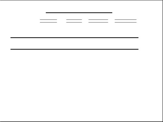
Electrical system analysis |
Chapter 2 |
|
|
CFSRD RADIAL SYSTEM 20 ST - MPSP
ENCOUNTER RATE AND DURATION OF THE DERATED STATES
|
O.RATE(0/yEAR) |
Av.OURCHOURS) |
T.O.TIMEcH/YEAR) |
POWER REDUCTION() |
|||
|
e.260BeE |
00 |
9.91451E |
e2 |
0.24589E |
e2 |
1 00 |
0.326805 |
BO |
0.45455E |
02 |
0.14525E |
02 |
Se |
|
|
|
|
|
|
|
|
• |
|
• EXPECTEO LOSS OF ENERCy DUE TO THE UNRELIABILITY OF THE STATION ELECTRICAL AUM/LIARY EQUIPMENT • |
||||||
|
• |
|
20738.450 |
116I145 |
|
|
• |
|
|
|
|
|
|
||
|
|
|
|
|
|
|
|
fONTINUE?y/N |
|
|
|
|
|
|
|
054SP-30 |
TUE, 13 DEC 1988 14:18:26 |
Flo. 2.44 Radial
purposes, is at the HV connections of the generator transformer and at the HV connections of the station transformer.
Variations of voltage and frequency on the grid system are transmitted to the power station electrical systems.
Station transformer fed supplies are not protected from step or rapid changes in voltage on the grid system, and their voltage profile closely follows that of the grid. In the longer term, the station transformer tap setting is adjusted manually to regulate the voltage of the systems supplied from it.
Supply systems derived from the Unit transformer are shielded from short term grid voltage variations by the action of the generator AVR, which adjusts the generator VAr output to maintain generator terminal voltage at an almost constant value, provided that upper and lower VAr output limits are not exceeded. In the longer term, the generator transformer tap setting may be adjusted to match the generator output to the supergrid/grid voltage, or to contribute to regulating supergrid/grid voltage.
system indices
The frequency of the whole of the SES is, of course, the same as the grid frequency, neglecting transient effects.
It follows from the above that the performance of the grid system is a major influence on the performance of a station electrical system. Adverse voltage regulation due to grid and internal causes cart be additive and influence the choice between installing transformers having on-load tapchangers and transformers having off-load tapchangers within the station electrical system.
The SESs are therefore examined with supergrid and grid voltages set to their extremes. This ensures that the tapping ranges on station and generator transformers are adequate.
3.2 Fault level analysis
3.2.1 Introduction
In the event of a fault occurring on a power station electrical system, energy will be released at the point
148
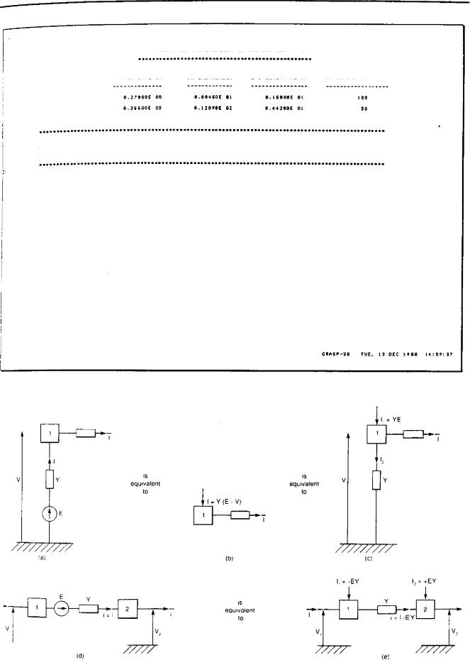
Power system performance analysis
CIF680 INTERCONNECTED SYSTEM 214 ST -MPSP
ENcowNTER RATE AND DURATION OF TAE OERA1E0 STATES
O.RPTE(0/YEARI |
AW.OURfHOURS) |
2.0.TImE(N/yEAR3 |
POWER REDUCTION(/.i |
|||||||
|
|
|
|
|
|
|
|
|
|
|
|
13.27000E 00 |
0.004SOE |
||||||||
|
|
|
8.16888E Al |
|||||||
|
|
|
|
100 |
|
|||||
|
0.3GSOOE 00 |
|
8.12090E 02 |
|
0.44280E 01 |
|
|
|
|
|
. |
|
|
|
|
|
SO |
• |
|||
|
|
|
|
|
|
|
|
|
||
. t,pEcTED LOSS OF ENERGY DUE TO THE uNRELIASILITY OF THE STATION ELECTRICAL AUXILIARY EQUIPMENT •
• |
8505.313 MUNO |
• |
• |
• |
|
• |
|
• |
mmTINUE? 7,1, |
|
|
CRASP-38 |
TOE, 13 DEC 1988 14:59:37 |
Fro. 2.45 Interconnected system indices
|
|
|
|
Is |
|||
|
Is |
||
equivalent |
|
equivalent |
|
to |
|
to |
fa} |
|
|
|
|
|
(b) |
Ic) |
||||
|
|
-EY |
|
= *EY |
|
|
|
|
|
|
|
|
|
|
|
|
|
|
|
|
|
|
|
|
|
|
|
|
|
is |
||
|
|
|
1 |
|
|
I |
|
|
|
|
equivalent |
|
|
|
|
|
|
|
|
|
|
|
|
|
|
||
|
|
|
|
|
|
|
|
|
|
to |
|
|
|
|
|
|
|
|
|
|
|
|
|
|
|
||
|
|
|
|
|
|
|
|
|
|
|
|||
|
V |
|
|
|
|
|
|
|
|
||||
|
|
V„ |
|
|
|
|
|||||||
/7777- |
|
|
|
|
|
|
|
|
|||||
|
|
|
|
|
|
|
|
|
|
||||
|
///// |
|
|
|
|
|
|||||||
|
|
|
|
|
ld |
|
|
|
|
|
|
|
|
|
|
|
|
|
|
|
|
|
|
|
|
(e) |
|
|
|
|
|
|
|
|
|
|
|
||||
FIG. 2.46 Replacement of a voltage source by an equivalent current source
149

Electrical system analysis |
|
|
|
|
|
|
|
|
|
|
|
|
|
|
|
|
|
|
|
|
Chapter 2 |
|||||||||||||
|
|
|
|
|
|
|
|
|
|
|
|
|
|
|
|
|
|
|
|
|||||||||||||||
GENERATOR A |
GENERATOR B |
|
|
|
|
|
GENERATOR D |
|||||||||||||||||||||||||||
|
|
|
|
|
|
|
|
|
|
|
|
|
|
|
|
|
|
|
|
|
|
|
|
|
0 |
|
|
|
|
|||||
|
|
|
|
|
|
LINE A-B |
|
|
|
|
|
|
|
|
LINE B-C |
|
|
|
|
LINE C-D |
|
|
||||||||||||
|
|
|
|
|
BUS A |
|
|
|
|
|
|
|
|
BUS B |
|
|
|
BUS C |
|
|
|
|
|
|
|
|
BUS |
|||||||
|
|
|
|
|
|
|
|
|
|
|
|
|
|
|
|
|
|
|
|
|
|
|
|
|||||||||||
|
|
|
|
|
|
|
|
|
|
|
||||||||||||||||||||||||
LOAD A |
LOAD B |
|
|
|
|
|
LOAD D |
|||||||||||||||||||||||||||
|
|
|
|
|
|
|
|
|
|
|
|
|
|
|
|
|
|
tal |
|
|
|
|
|
|
|
|
|
|
|
|
|
|||
|
|
|
|
|
|
|
|
|
|
|
|
|
|
|
|
|
|
|
|
|
|
|
|
|
|
|
|
|
|
|
|
|
|
|
|
|
|
|
|
|
|
|
|
ic |
|
|
|
|
|
id |
|||||||||||||||||||
|
|
|
|
|
|
|
|
|
|
|
|
|
ib |
|
|
|
||||||||||||||||||
|
|
|
|
|
|
|
|
|
|
|
|
|
|
|
|
|
|
|
||||||||||||||||
|
|
|
|
|
|
|
|
|
|
|
|
|
|
|
|
|
|
|
|
|
|
|
|
|
|
|
|
|
|
|
|
|||
|
|
|
|
|
|
|
|
|
|
|
|
|
|
|
|
|
|
Y2 |
|
|
|
|
|
|
|
Y3 |
||||||||
|
|
|
|
|
|
|
Y1 |
|
|
|
|
|
|
|
|
|
|
|
|
|
|
|
||||||||||||
|
|
|
|
|
|
|
|
|
|
|
|
|
|
|
|
|
|
|
|
|
|
|
|
7-1 |
|
|
|
|
|
|
|
|
||
|
a |
|
|
|
|
|
|
|
|
|
|
|
|
|
|
|
|
|
|
|
|
|||||||||||||
|
|
|
|
|
|
|
|
|
|
|
|
|
|
|
|
|
|
|
|
|
|
|
|
|
|
|
|
|
|
|||||
|
|
|
|
|
|
|
|
|
|
|
|
|
Y6 |
|||||||||||||||||||||
|
|
|
|
|
y4 |
|
|
|
|
|
Y5 |
|
|
|
|
|
|
|
|
|
|
|
|
|
||||||||||
|
|
|
|
|
|
|
|
|
|
|
|
|
|
|
|
|
|
|
|
|
|
|
|
|
|
|
|
|
||||||
|
|
|
|
|
|
|
|
|
|
|
|
|
|
|
|
|
|
|
|
|
|
|
|
|
|
|
|
|
|
|
|
|
|
|
//////////////////// /77 //
(b)
Fa. 2.47 A simple power system and equivalent network diagram developed for use in nodal analysis
of the fault. Currents greatly in excess of normal may flow and considerable damage result. Synchronous machines and induction machines possess kinetic energy and magnetic field energy, and so contribute to the fault current. Both types of machine supply a current which decreases with time. The induction machine current decays to a small value comparatively quickly, because it has no DC supplied field winding. A synchronous machine fault current decreases to a steady state value in roughly 0.5-1.5 s. The steady state value may be about 0.6 x full-load rating of the machine. Precise values of decay time, initial fault current and final fault current depend on the design of the particular machine. Figure 2.70 shows how the fault current of a synchronous machine varies with ti me.
It is essential to detect faults and to isolate faulty equipment, so protection schemes are designed to detect abnormal conditions in the shortest possible time and initiate operation of switchgear to electrically isolate the faulty equipment. The speed of disconnection is important since the extent of damage also depends on the time for which fault current flows. Furthermore, fast fault clearance makes system recovery easier.
All switchgear has specified fault current make and break ratings. Electrical supply systems are designed such that the prospective fault current resulting from
any postulated fault does not exceed the capability of the circuit-breaker which must clear that fault.
Power station electrical systems are so designed that the fault levels are often well below permitted maximums during normal operating modes. Higher fault levels occur when paralleling two normally separate paths, possibly to take plant out of service or, more often, when running up and shutting down main generating plant. Higher fault levels also occur when auxiliary gas turbines or diesel-driven generators are run in parallel with the main system.
The usual way to limit three-phase fault current in power station electrical systems at the design stage is to modify transformer reactance. Increasing a transformer reactance reduces the fault levels on the boards it feeds, but at the same time increases voltage regulation (the voltage drop produced by load current) at these boards. The designer must balance these conflicting requirements — low transformer impedance for good system regulation, i.e., low voltage drop, against high transformer impedance to reduce fault current — and produce a satisfactory compromise. There are other ways of reducing fault levels, e.g., auxiliary generator reactances can be increased. On the power station electrical systems considered here, gas-turbine generators and diesel generators may have their reactances increased to some extent, but stability
150

Power system performance analysis
Read in initial voltages busbar data and
form nodal Y matrix
(a)
|
|
ITER |
|
|
ITERATION NUMBER |
I ITER = ITER |
|
|
|
|
NODE OR BUSBAFI |
0 |
|
IDENTIFICATION |
|
|
NUMBER |
|
|
|
'1r
|
|
|
|
|
|
|
BUSBAR i? |
PV |
|
CALCULATE |
|||||||||
|
|
|
|
|
|
|
SLACK .1TP- |
|
|||||||||||
|
|
|
|
|
|
|
|
NETT BUSBAR 0 |
|||||||||||
|
|
|
|
|
|
|
|
|
|
|
|
|
|
|
|
|
|
||
|
|
|
|
|
|
|
|
|
|
|
|
|
|
|
|
|
|
|
|
|
|
|
|
|
|
|
|
|
|
|
|
|
|
|
|
|
|
|
|
|
|
|
|
|
|
|
|
|
|
|
|
|
|
|
|
|
|
|
|
|
|
|
APPLY ALGORITHM TO |
|
|
|
|
||||||||||||
|
|
|
|
|
|
|
|
GET Vi |
|
|
|
|
|
|
|
|
|||
|
|
|
|
|
|
|
|
|
|
|
|
|
|
|
YES |
|
|
|
|
|
|
|
|
|
|
|
|
BUSBAR |
|
|
|
|
RATIO Vi to. |
||||||
|
|
|
|
|
|
|
|
|
PV? |
|
|
|
|
|
SPECIFIED VALUE |
||||
|
|
|
|
|
|
|
|
|
NO |
|
|
|
|
|
|
|
|
|
|
|
|
|
|
|
|
|
|
|
|
|
|
|
|
|
|
|
|
|
|
|
|
|
|
|
|
|
|
|
|
|
|
|
|
|
|
|
|
n = NUMBER |
|
|
|
|
|
|
|
|
|
i = n? |
|
|
|
|
|
|
|||||
|
|
|
|
|
|
|
|
|
|
|
|
|
|
OF BUSBARS |
|||||
|
|
|
|
|
|
|
|
|
|
|
|
|
|
|
|
|
|
||
|
|
|
|
|
|
|
|
|
YES |
|
|
|
|
|
|
|
|
||
|
|
|
|
|
|
|
|
|
|
|
|
|
|||||||
|
|
|
|
|
|
|
SOLUTION |
|
>YES |
|
|
||||||||
|
|
|
|
|
|
|
CONVERGED? |
|
|
||||||||||
|
|
|
|
|
|
|
|
|
|||||||||||
|
|
|
|
|
|
|
|
|
NO |
|
|
|
|
|
|
|
|
||
|
|
|
|
|
|
|
|
|
|
|
|
|
|
|
|
|
|
|
|
|
|
- Kt |
|
|
|
|
ITER |
|
|
|
|
YES |
|
|
|||||
|
|
AXIMUM ITERATIONS, ? |
|
|
|||||||||||||||
|
|
|
|
||||||||||||||||
FIG. 2.48 Logic flow diagram for the
Gauss-Seidel method
and regulation are adversely affected and must be taken into account if this is done. Inductors can be used to reduce system fault levels — again stability and regulation must be taken into account. Converter/ inverter supplied motors make no fault current contribution and because of this are a major advantage in containing system fault levels. However, they also generate harmonics, so analysis is needed to show whether the levels produced are acceptable. They have a higher initial cost than ordinary induction motors, but this is offset by high efficiency at part load, so overall lifetime cost analysis is necessary in considering their use.
a
Y..
(b)
FIG. 2.49 Method of accommodating off-nominal transformer tappings by incorporating off-nominal tap representation into the admittance matrix
FIG. 2.50 Simple w circuit deduced when off-nominal taps are in phase
FIG. 2.51 Alternative method of representing off-nominal transformer taps
3.2.2 Program construction
General remarks
Most of a power station electrical system is designed on the basis of complete phase symmetry. In other words, the loads on each phase are the same and the voltages (and currents) are equal in magnitude and phase, displaced by 120 0 and 2400 .
At lower voltages, there is some unbalance where single phase supplies are provided but at higher voltages, where supplies are almost exclusively to induction motors and other three-phase loads, symmetry can be assumed during normal operation.
In analysis terms, this means that knowledge of the voltage and current in one phase implies knowledge of
151

Electrical system analysis |
Chapter 2 |
||
|
|
|
|
|
|
|
|
NETWORK DIAGRAM DRAWING AND MODIFYING
1 32KV
23ICYG
FPH |
BHS1 |
NYC, |
CHL |
JETTY |
IPSASEK 23 Jun 1961 03 31,35
FIG. 2.52 Analysis diagram of a SES in an oil-fired power station
FIG. 2.53 Analysis diagram of a SES in an AGR nuclear power station
152