

plc basic functions - 15.25
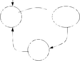
15.4.4 Flashing Lights
Problem: We are designing a movie theater marquee, and they want the traditional flashing lights. The lights have been connected to the outputs of the PLC from O:001/00 to O:001/17. When the PLC is turned, every second light should be on. Every half second the lights should reverse. The result will be that in one second two lights side-by-side will be on half a second each.
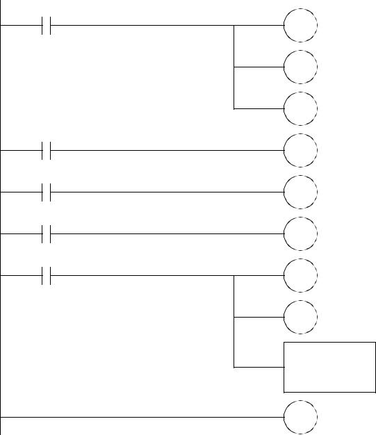
Solution: |
|
|||
|
|
|
|
|
|
|
|
T4:1/DN |
TON |
|
|
|
|
timer T4:0 |
|
|
|
|
|
|
|
|
|
Delay 0.5s |
|
|
|
|
|
|
|
|
|
|
|
|
|
T4:0/DN |
TON |
|
|
|
|
timer T4:1 |
|
|
|
|
|
|
|
|
|
Delay 0.5s |
|
|
|
|
|
|
|
|
|
|
|
|
|
T4:0/TT |
MOV |
|
|
|
|
Source B3:0 |
|
|
|
|
|
|
|
|
|
Dest O:001 |
|
|
|
|
|
|
|
|
|
|
|
|
|
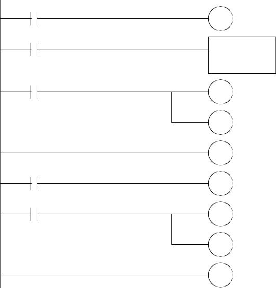
T4:0/TT |
NOT |
|
|
|
|
Source B3:0 |
|
|
|
|
|
|
|
|
|
Dest O:001 |
|
|
|
|
|
|
B3:0 = 0101 0101 0101 0101 |
|
||
|
Figure 15.27 A Flashing Light Example |
|
||
15.5SUMMARY
•Functions can get values from memory, do simple operations, and return the results to memory.
•Scientific and statistics math functions are available.
•Masked function allow operations that only change a few bits.
•Expressions can be used to perform more complex operations.
•Conversions are available for angles and BCD numbers.
•Array oriented file commands allow multiple operations in one scan.
plc basic functions - 15.26
•Values can be compared to make decisions.
•Boolean functions allow bit level operations.
•Function change value in data memory immediately.
15.6PRACTICE PROBLEMS
1. Do the calculation below with ladder logic,
N7:2 = -(5 - N7:0 / N7:1)
2. Implement the following function,
y + log ( y) |
|
x = atan y |
------------------------y + 1 |
3.A switch will increment a counter on when engaged. This counter can be reset by a second switch. The value in the counter should be multiplied by 5, and then displayed as a binary output using (O:000)
4.Create a ladder logic program that will start when input A is turned on and calculate the series below. The value of n will start at 0 and with each scan of the ladder logic n will increase by 2 until n=20. While the sequence is being incremented, any change in A will be ignored.
x = 2( log ( n) – 1) |
A = B3/10 |
|
n = N7:0 |
|
x = F8:15 |
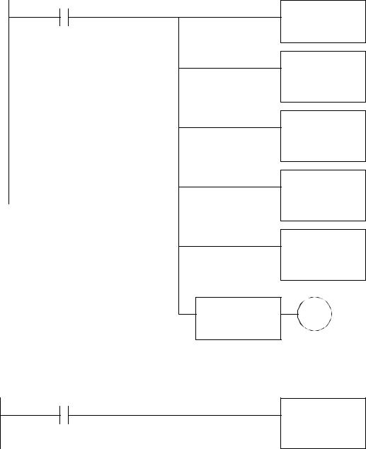
5.The following program uses indirect addressing. Indicate what the new values in memory will be when button A is pushed after the first and second instructions.
|
|
|
A |
|
|
|
|
|
ADD |
|
|
|
|
|
|
|
|
|
|
|
|
|
|
|
|
|
|
|
|
|
|
|
|
|
|
|
|
|
Source A 1 |
|
|
|
|
|
|
|
|
|
|
|
|
|
|
|
|
|
|
|
Source B N7:0 |
|
|
|
|
|
|
|
|
|
Dest. N7:[N7:1] |
|
|
|
A |
|
|
|
|
|
|
|
|
|
|
|
|
|
|
|
|
|
|
|
|
|
|
|
|
ADD |
|
|
|
|
|
|
|
|
|
|
|
|
|
|
|
|
|
|
|
|
|
|
|
|
|
|
|
|
|
|
Source A N7:[N7:0] |
|
|
|
|
|
|
|
|
|
|
|
addr |
|
before |
|
after 1st |
|
after 2nd |
Source B N7:[N7:1] |
|
|
|
|
|
||||||
|
|
|
|
Dest. N7:[N7:0] |
|||||
|
|
|
|
|
|
|
|
|
|
|
N7:0 |
1 |
|
|
|
|
|
|
|
|
N7:1 |
2 |
|
|
|
|
|
|
|
|
|
|
|
|
|
|
|||
|
N7:2 |
3 |
|
|
|
|
|
|
|
|
|
|
|
|
|
|
|
|
|

plc basic functions - 15.27
6.A thumbwheel input card acquires a four digit BCD count. A sensor detects parts dropping down a chute. When the count matches the BCD value the chute is closed, and a light is turned on until a reset button is pushed. A start button must be pushed to start the part feeding. Develop the ladder logic for this controller. Use a structured design technique such as a state diagram.
INPUT |
OUTPUT |
I:000 - BCD input card |
O:002/00 - chute open |
I:001/00 - part detect |
O:002/01 - light |
I:001/01 - start button |
|
I:001/02 - reset button |
|
7.Describe the difference between incremental, all and a number for file oriented instruction, such as FAL.
8.What is the maximum number of elements that moved with a file instruction? What might happen if too many are transferred in one scan?
9.Write a ladder logic program to do the following calculation. If the result is greater than 20.0, then the output O:012/15 will be turned on.
T |
|
|
–--- |
|
|
A = D – Be C |
where, |
A = F8:0 |
|
|
B = F8:1 |
|
|
C = F8:2 |
|
|
D = F8:3 |
|
|
T = F8:4 |
10.Write ladder logic to reset an RTO counter (T4:0) without using the RES instruction.
11.Write a program that will use Boolean operations and comparison functions to determine if bits 9, 4 and 2 are set in the input word I:001. If they are set, turn on output bit O:000/4.
12.Explain how the mask works in the following MVM function. Develop a Boolean equation.
MVM
Source N7:0
Mask N7:1
Dest N7:2

plc basic functions - 15.28
15.7 PRACTICE PROBLEM SOLUTIONS
1.
2.
y = F8:0 x = F8:6
DIV
Source A N7:0
Source B N7:1
Dest N7:2
SUB
Source A 5
Source B N7:2
Dest N7:2
NEG
Source N7:2
Dest N7:2
LOG
Source F8:0
Dest F8:1
ADD
Source A F8:0
Source B F8:1
Dest F8:2
ADD
Source A F8:0
Source B 1
Dest F8:3
DIV
Source A F8:2
Source B F8:3
Dest F8:4
MUL
Source A F8:0
Source B F8:4
Dest F8:5
ATN
Source F8:3
Dest F8:6

|
|
|
|
|
|
|
|
|
|
plc basic functions - 15.29 |
|
|
|
|
|
|
|
|||
3. |
|
|
|
|
|
|
|
|
|
|
|
|
|
|
|
|
|
|
|
|
|
|
|
|
|
count |
|
|
|
|
|
|
|
|
|
|
|
||||
|
|
|
|
|
|
|
|
|
|
|
|
|
|
|
|
|||||
|
|
|
|
|
|
|
|
|
CTU |
|||||||||||
|
|
|
|
|
|
|
|
|
|
|
|
|
|
|
|
|
Counter C5:0 |
|
|
|
|
|
|
|
|
|
|
|
|
|
|
|
|
|
|
|
|
||||
|
|
|
|
|
reset |
|
|
|
|
|
|
|
Preset 1234 |
|
|
|||||
|
|
|
|
|
|
|
|
|
|
|
|
|
|
|
|
|||||
|
|
|
|
|
|
|
|
|
|
|
|
|
|
|
|
|||||
|
|
|
|
|
|
|
|
|
|
|
|
|
|
|
|
|
RES C5:0 |
|||
|
|
|
|
|
|
|
|
|
|
|
|
|
|
|
|
|
||||
|
|
|
|
|
|
|
|
|
|
|
|
|
|
|
|
|
|
|
|
|
|
|
|
|
|
|
|
|
|
|
|
|
|
|
|
|
|
MUL |
|||
|
|
|
|
|
|
|
|
|
|
|
|
|
|
|
|
|
Source A 5 |
|||
|
|
|
|
|
|
|
|
|
|
|
|
|
|
|
|
|
Source B C5:0.ACC |
|||
|
|
|
|
|
|
|
|
|
|
|
|
|
|
|
|
|
||||
|
|
|
|
|
|
|
|
|
|
|
|
|
|
|
|
|
Dest O:000 |
|||
4. |
|
|
|
|
|
|
|
|
|
|
|
|
|
|
|
|
|
|
|
|
|
|
|
|
|
|
|
|
|
|
|
|
|
|
|
|
|
|
|
|
|
|
|
|
|
|
A |
|
|
|
|
|
|
|
|
|
|
|
|
|||
|
|
|
|
|
|
|
|
|
|
EQ |
|
|
|
|
|
MOV |
|
|
||
|
|
|
|
|
|
|
|
|
|
Source A 20 |
|
|
|
|
|
Source -2 |
|
|
||
|
|
|
|
|
|
|
|
|
|
|
|
|
|
|
||||||
|
|
|
|
|
|
|
|
|
|
Source B N7:0 |
|
|
|
|
|
Dest N7:0 |
|
|
||
|
|
|
|
|
|
|
|
|
|
|
|
|
|
|
|
|
|
|||
|
|
|
|
|
|
|
|
|
|
|
|
|
|
|
|
|||||
|
|
|
|
LES |
|
|
|
|
|
|
|
ADD |
|
|||||||
|
|
|
|
Source A N7:0 |
|
|
|
|
|
|
|
Source A N7:0 |
|
|||||||
|
|
|
|
|
|
|
|
|
|
|
||||||||||
|
|
|
|
Source B 20 |
|
|
|
|
|
|
|
Source B 2 |
|
|||||||
|
|
|
|
|
|
|
|
|
|
|
|
|
|
|
|
|
Dest N7:0 |
|
||
|
|
|
|
|
|
|
|
|
|
|
|
|
|
|
|
|
||||
|
|
|
|
|
|
|
|
|
|
|
|
|
|
|
|
|
|
|
|
|
|
|
|
|
|
|
|
|
|
|
|
|
|
|
|
|
|
|
|
|
|
|
|
|
|
|
|
|
|
|
|
|
|
|
|
|
|
|
LOG |
|||
|
|
|
|
|
|
|
|
|
|
|
|
|
|
|
|
|
||||
|
|
|
|
|
|
|
|
|
|
|
|
|
|
|
|
|
Source N7:0 |
|
||
|
|
|
|
|
|
|
|
|
|
|
|
|
|
|
|
|
Dest F8:15 |
|
||
|
|
|
|
|
|
|
|
|
|
|
|
|
|
|
|
|
|
|
|
|
|
|
|
|
|
|
|
|
|
|
|
|
|
|
|
|
|
|
|
|
|
|
|
|
|
|
|
|
|
|
|
|
|
|
|
|
|
|
SUB |
|||
|
|
|
|
|
|
|
|
|
|
|
|
|
|
|
|
|
Source A F8:15 |
|
||
|
|
|
|
|
|
|
|
|
|
|
|
|
|
|
|
|
|
|||
|
|
|
|
|
|
|
|
|
|
|
|
|
|
|
|
|
Source B 1 |
|
||
|
|
|
|
|
|
|
|
|
|
|
|
|
|
|
|
|
Dest F8:15 |
|
||
|
|
|
|
|
|
|
|
|
|
|
|
|
|
|
|
|
|
|
|
|
|
|
|
|
|
|
|
|
|
|
|
|
|
|
|
|
|
|
|
|
|
|
|
|
|
|
|
|
|
|
|
|
|
|
|
|
|
|
MUL |
|||
|
|
|
|
|
|
|
|
|
|
|
|
|
|
|
|
|
Source A F8:15 |
|
||
|
|
|
|
|
|
|
|
|
|
|
|
|
|
|
|
|
|
|||
|
|
|
|
|
|
|
|
|
|
|
|
|
|
|
|
|
Source B 2 |
|
||
|
|
|
|
|
|
|
|
|
|
|
|
|
|
|
|
|
Dest F8:15 |
|
||
5. |
|
|
|
|
|
|
|
|
|
|
|
|
|
|
|
|
|
|
|
|
|
|
|
|
|
|
|
|
|
|
|
|
|
|
|
|
|
|
|
|
|
|
|
|
|
|
|
|
|
addr |
|
before |
|
after 1st |
|
after 2nd |
||||||
|
|
|
|
|
|
|
|
|
|
|
||||||||||
|
|
|
|
|
|
|
|
|
|
|
|
|
|
|
|
|
|
|
||
|
|
|
|
|
|
|
|
N7:0 |
|
1 |
|
1 |
|
1 |
|
|
|
|
||
|
|
|
|
|
|
|
|
N7:1 |
|
2 |
|
2 |
|
4 |
|
|
|
|
||
|
|
|
|
|
|
|
|
N7:2 |
|
3 |
|
2 |
|
2 |
|
|
|
|
||
|
|
|
|
|
|
|
|
|
|
|
|
|
|
|
|
|
|
|
|
|
plc basic functions - 15.30
6.
first scan
S1
waiting
reset
start S2
 parts counting (chute open)
|
count |
S3 |
exceeded |
bin full
(light on)
plc basic functions - 15.31
first scan
L S1
U S2
U S3
S2
chute
S3
light
S1
MCR
start
L S2
U S1
FRD
Source A I:000
Dest. C5:0/ACC
MCR
plc basic functions - 15.32
S2
MCR
part detect
CTD counter C5:0 preset 0
C5:0/DN
L S3
U S2
MCR
S3
MCR
reset
L S1
U S3
MCR
7.an incremental mode will do one calculation when the input to the function is a positive edge - goes from false to true. The all mode will attempt to complete the calculation in a single scan. If a number is used, the function will do that many calculations per scan while the input is true.
8.The maximum number is 1000. If the instruction takes too long the instruction may be paused and continued the next scan, or it may lead to a PLC fault because the scan takes too long.
plc basic functions - 15.33
9.
GRT
Source A F8:0
Source B 20.0
10.
reset
NEG
Source F8:4
Dest F8:0
DIV
Source A F8:0
Source B F8:2
Dest F8:0
XPY
Source A 2.718
Source B F8:0
Dest F8:0
MUL
Source A F8:1
Source B F8:0
Dest F8:0
SUB
Source A F8:3
Source B F8:0
Dest F8:0
O:012/15
MOV
Source 0
Dest T4:0.ACC