- •9.7.2 More Timers And Counters
- •9.7.3 Deadman Switch
- •9.7.4 Conveyor
- •9.7.5 Accept/Reject Sorting
- •9.7.6 Shear Press
- •9.8 SUMMARY
- •9.9 PRACTICE PROBLEMS
- •9.10 PRACTICE PROBLEM SOLUTIONS
- •9.11 ASSIGNMENT PROBLEMS
- •10. STRUCTURED LOGIC DESIGN
- •10.1 INTRODUCTION
- •10.2 PROCESS SEQUENCE BITS
- •10.3 TIMING DIAGRAMS
- •10.4 DESIGN CASES
- •10.5 SUMMARY
- •10.6 PRACTICE PROBLEMS
- •10.7 PRACTICE PROBLEM SOLUTIONS
- •10.8 ASSIGNMENT PROBLEMS
- •11. FLOWCHART BASED DESIGN
- •11.1 INTRODUCTION
- •11.2 BLOCK LOGIC
- •11.3 SEQUENCE BITS
- •11.4 SUMMARY
- •11.5 PRACTICE PROBLEMS
- •11.6 PRACTICE PROBLEM SOLUTIONS
- •11.7 ASSIGNMENT PROBLEMS
- •12. STATE BASED DESIGN
- •12.1 INTRODUCTION
- •12.1.1 State Diagram Example
- •12.1.2 Conversion to Ladder Logic
- •12.1.2.1 - Block Logic Conversion
- •12.1.2.2 - State Equations
- •12.1.2.3 - State-Transition Equations
- •12.2 SUMMARY
- •12.3 PRACTICE PROBLEMS
- •12.4 PRACTICE PROBLEM SOLUTIONS
- •12.5 ASSIGNMENT PROBLEMS
- •13. NUMBERS AND DATA
- •13.1 INTRODUCTION
- •13.2 NUMERICAL VALUES
- •13.2.1 Binary
- •13.2.1.1 - Boolean Operations
- •13.2.1.2 - Binary Mathematics
- •13.2.2 Other Base Number Systems
- •13.2.3 BCD (Binary Coded Decimal)
- •13.3 DATA CHARACTERIZATION
- •13.3.1 ASCII (American Standard Code for Information Interchange)
- •13.3.2 Parity
- •13.3.3 Checksums
- •13.3.4 Gray Code
- •13.4 SUMMARY
- •13.5 PRACTICE PROBLEMS
- •13.6 PRACTICE PROBLEM SOLUTIONS
- •13.7 ASSIGNMENT PROBLEMS
- •14. PLC MEMORY
- •14.1 INTRODUCTION
- •14.2 MEMORY ADDRESSES
- •14.3 PROGRAM FILES
- •14.4 DATA FILES
- •14.4.1 User Bit Memory
- •14.4.2 Timer Counter Memory
- •14.4.3 PLC Status Bits (for PLC-5s and Micrologix)
- •14.4.4 User Function Control Memory
- •14.4.5 Integer Memory
- •14.4.6 Floating Point Memory
- •14.5 SUMMARY
- •14.6 PRACTICE PROBLEMS
- •14.7 PRACTICE PROBLEM SOLUTIONS
- •14.8 ASSIGNMENT PROBLEMS
- •15. LADDER LOGIC FUNCTIONS
- •15.1 INTRODUCTION
- •15.2 DATA HANDLING
- •15.2.1 Move Functions
- •15.2.2 Mathematical Functions
- •15.2.3 Conversions
- •15.2.4 Array Data Functions
- •15.2.4.1 - Statistics
- •15.2.4.2 - Block Operations
- •15.3 LOGICAL FUNCTIONS
- •15.3.1 Comparison of Values
- •15.3.2 Boolean Functions
- •15.4 DESIGN CASES
- •15.4.1 Simple Calculation
- •15.4.2 For-Next
- •15.4.3 Series Calculation
- •15.4.4 Flashing Lights
- •15.5 SUMMARY
- •15.6 PRACTICE PROBLEMS
- •15.7 PRACTICE PROBLEM SOLUTIONS
- •15.8 ASSIGNMENT PROBLEMS
plc memory - 14.1
14. PLC MEMORY
Topics:
•PLC-5 memory types; program and data
•Data types; output, input, status, bit, timer, counter, integer, floating point, etc.
•Memory addresses; words, bits, data files, expressions, literal values and indirect.
Objectives:
•To know the basic memory types available
•To be able to use addresses for locations in memory
14.1INTRODUCTION
Advanced ladder logic functions allow controllers to perform calculations, make decisions and do other complex tasks. Timers and counters are examples of ladder logic functions. They are more complex than basic input contacts and output coils and they rely upon data stored in the memory of the PLC. The memory of the PLC is organized to hold different types of programs and data.
14.2 MEMORY ADDRESSES
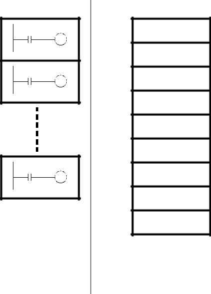
The memory in a PLC is organized by data type as shown in Figure 14.1. There are two fundamental types of memory used in Allen-Bradley PLCs - Program and Data memory. Memory is organized into blocks of up to 1000 elements in an array called a file. The Program file holds programs, such as ladder logic. There are eight Data files defined by default, but additional data files can be added if they are needed.
plc memory - 14.2
Program Files
2
3
999
These are a collection of up to 1000 slots to store up to 1000 programs. The main program will be stored in program file 2. SFC programs must be in file 1, and file 0 is used for program and password information. All other program files from 3 to 999 can be used for subroutines.
Figure 14.1 PLC Memory
Data Files
O0 Outputs
I1 Inputs
S2 Status
B3 Bits
T4 Timers
C5 Counters
R6 Control
N7 Integer
F8 Float
This is where the variable data is stored that the PLC programs operate on. This is quite complicated, so a detailed explanation follows.
14.3 PROGRAM FILES
In a PLC-5 the first three program files, from 0 to 2, are defined by default. File 0 contains system information and should not be changed, and file 1 is reserved for SFCs. File 2 is available for user programs and the PLC will run the program in file 2 by default. Other program files can be added from file 3 to 999. Typical reasons for creating other