

plc flowchart - 11.26
11.7 ASSIGNMENT PROBLEMS
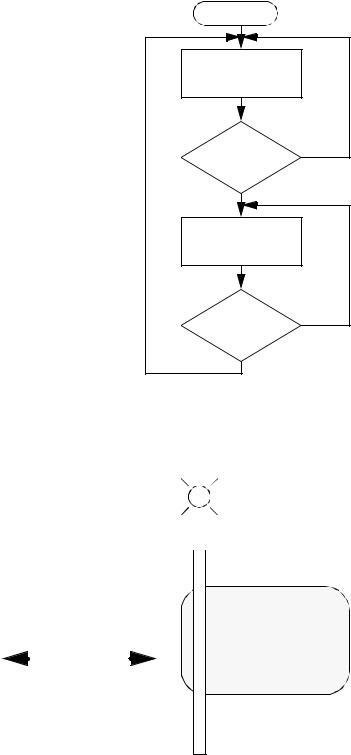
1. Develop ladder logic for the flowchart below. |
|
|
Start |
|
|
Turn A on |
|
|
Is B |
no |
|
on? |
||
|
||
yes |
|
|
Turn A off |
|
|
Is C |
|
|
on? |
yes |
|
|
||
no |
|
2. Use a flow chart to design a parking gate controller.
keycard entry |
|
light |
||
|
|
|||
|
|
|
|
|
|
|
|
|
|
gate
cars enter/leave |
car detector |
|
|
|
|
|
|
|
|
|
|
-the gate will be raised by one output and lowered by another. If the gate gets stuck an over current detector will make a PLC input true. If this is the case the gate should reverse and the light should be turned on indefinitely.
-if a valid keycard is entered a PLC input will be true. The gate is to rise and stay open for 10 seconds.
-when a car is over the car detector a PLC input will go true. The gate is to open while this detector is active. If it is active for more that 30 seconds the light should also turn on until the gate closes.
plc flowchart - 11.27
3.A welding station is controlled by a PLC. On the outside is a safety cage that must be closed while the cell is active. A belt moves the parts into the welding station and back out. An inductive proximity sensor detects when a part is in place for welding, and the belt is stopped. To weld, an actuator is turned on for 3 seconds. As normal the cell has start and stop push buttons.
a)Draw a flow chart
b)Implement the chart in ladder logic
Inputs |
Outputs |
DOOR OPEN (NC) |
CONVEYOR ON |
START (NO) |
WELD |
STOP (NC) |
|
PART PRESENT |
|
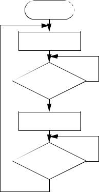
4. Convert the following flowchart to ladder logic.
Start |
|
Turn off motor |
|
start |
no |
pushed |
|
yes |
|
Turn on motor |
|
stop |
no |
pushed |
|
yes |
|
5.A machine is being designed to wrap boxes of chocolate. The boxes arrive at the machine on a conveyor belt. The list below shows the process steps in sequence.
1.The box arrives and is detected by an optical sensor (P), after this the conveyor is stopped (C) and the box is clamped in place (H).
2.A wrapping mechanism (W) is turned on for 2 seconds.
3.A sticker cylinder (S) is turned on for 1 second to put consumer labelling on the
plc flowchart - 11.28
box.
4.The clamp (H) is turned off and the conveyor (C) is turned on.
5.After the box leaves the system returns to an idle state.
Develop ladder logic for the system using a flowchart. Don’t forget to include regular start and stop inputs.