

plc flowchart - 11.1
11. FLOWCHART BASED DESIGN
Topics:
•Describing process control using flowcharts
•Conversion of flowcharts to ladder logic Objectives:
•Ba able to describe a process with a flowchart.
•Be able to convert a flowchart to ladder logic.
11.1INTRODUCTION
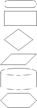
A flowchart is ideal for a process that has sequential process steps. The steps will be executed in a simple order that may change as the result of some simple decisions. The symbols used for flowcharts are shown in Figure 11.1. These blocks are connected using arrows to indicate the sequence of the steps. The different blocks imply different types of program actions. Programs always need a start block, but PLC programs rarely stop so the stop block is rarely used. Other important blocks include operations and decisions. The other functions may be used but are not necessary for most PLC applications.
Start/Stop
Operation
Decision
I/O
Disk/Storage
Subroutine
Figure 11.1 Flowchart Symbols
plc flowchart - 11.2
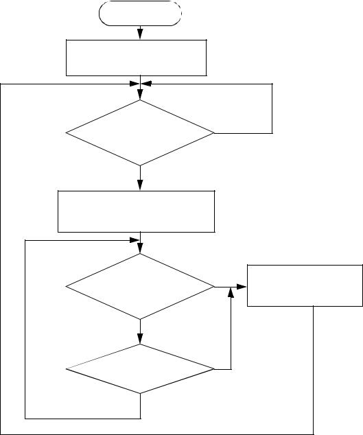
A flowchart is shown in Figure 11.2 for a control system for a large water tank. When a start button is pushed the tank will start to fill, and the flow out will be stopped. When full, or the stop button is pushed the outlet will open up, and the flow in will be stopped. In the flowchart the general flow of execution starts at the top. The first operation is to open the outlet valve and close the inlet valve. Next, a single decision block is used to wait for a button to be pushed. when the button is pushed the yes branch is followed and the inlet valve is opened, and the outlet valve is closed. Then the flow chart goes into a loop that uses two decision blocks to wait until the tank is full, or the stop button is pushed. If either case occurs the inlet valve is closed and the outlet valve is opened. The system then goes back to wait for the start button to be pushed again. When the controller is on the program should always be running, so only a start block is needed. Many beginners will neglect to put in checks for stop buttons.
plc flowchart - 11.3
START
Open outlet valve
Close inlet valve
start button pushed? |
no |
|
|
|
|
yes |
|
|
Open inlet valve |
|
|
Close outlet valve |
|
|
|
yes |
Open outlet valve |
Is tank full? |
|
|
|
Close inlet valve |
|
|
|
|
no |
|
|
stop button pushed? |
yes |
|
|
|
|
no |
|
|
Figure 11.2 A Flowchart for a Tank Filler
The general method for constructing flowcharts is:
1.Understand the process.
2.Determine the major actions, these are drawn as blocks.
3.Determine the sequences of operations, these are drawn with arrows.
plc flowchart - 11.4
4. When the sequence may change use decision blocks for branching.
Once a flowchart has been created ladder logic can be written. There are two basic techniques that can be used, the first presented uses blocks of ladder logic code. The second uses normal ladder logic.
11.2 BLOCK LOGIC
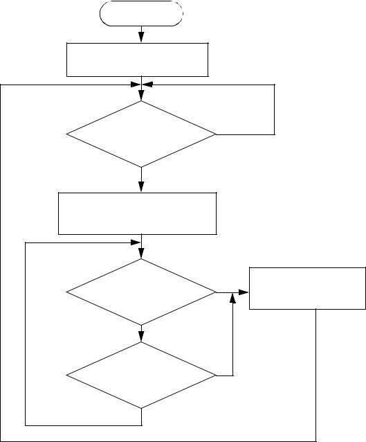
The first step is to name each block in the flowchart, as shown in Figure 11.3. Each of the numbered steps will then be converted to ladder logic
plc flowchart - 11.5
STEP 1: Add labels to each block in the flowchart
START
F1
Open outlet valve
Close inlet valve
|
F2 |
|
|
|
start button pushed? |
no |
|
|
|
|
|
F3 |
yes |
|
|
|
|
|
|
|
Open inlet valve |
|
|
|
Close outlet valve |
|
|
|
|
|
F6 |
F4 |
Is tank full? |
yes |
Open outlet valve |
|
|
||
|
|
Close inlet valve |
|
|
|
|
|
|
no |
|
|
F5 |
|
|
|
|
stop button pushed? |
yes |
|
|
|
|
|
|
no |
|
|
Figure 11.3 Labeling Blocks in the Flowchart
Each block in the flowchart will be converted to a block of ladder logic. To do this we will use the MCR (Master Control Relay) instruction (it will be discussed in more detail later.) The instruction is shown in Figure 11.4, and will appear as a matched pair of outputs labelled MCR. If the first MCR line is true then the ladder logic on the following lines will be scanned as normal to the second MCR. If the first line is false the lines to the
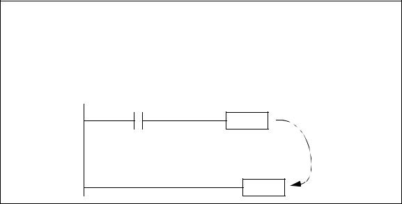
plc flowchart - 11.6
next MCR block will all be forced off. If a normal output is used inside an MCR block, it may be forced off. Therefore latches will be used in this method.
Note: We will use MCR instructions to implement some of the state based programs. This allows us to switch off part of the ladder logic. The one significant note to remember is that any normal outputs (not latches and timers) will be FORCED OFF. Unless this is what you want, put the normal outputs outside MCR blocks.
A
MCR
If A is true then the MCR will cause the ladder in between to be executed. If A is false the outputs are forced off.
MCR
Figure 11.4 The MCR Function
The first part of the ladder logic required will reset the logic to an initial condition, as shown in Figure 11.5. The line will only be true for the first scan of the PLC, and at that time it will turn on the flowchart block F1 which is the reset all values off operation. All other operations will be turned off.
plc flowchart - 11.7
STEP 2: Write ladder logic to force the PLC into the first state
first scan
F1
L
F2
U
F3
U
F4
U
F5
U
F6
U
Figure 11.5 Initial Reset of States
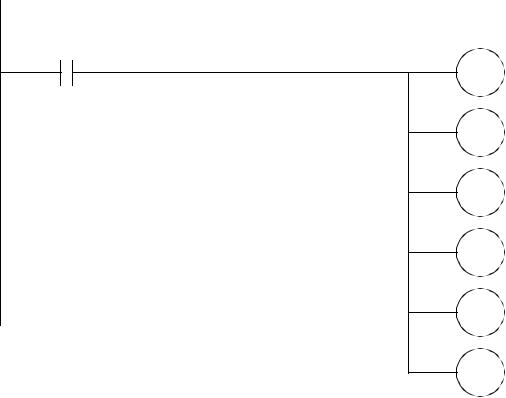
The ladder logic for the first state is shown in Figure 11.6. When F1 is true the logic between the MCR lines will be scanned, if F1 is false the logic will be ignored. This logic turns on the outlet valve and turns off the inlet valve. It then turns off operation F1, and turns on the next operation F2.
plc flowchart - 11.8
STEP 3: Write ladder logic for each function in the flowchart
F1
MCR
outlet
L
inlet
U
F1
U
F2
L
MCR
Figure 11.6 Ladder Logic for the Operation F1
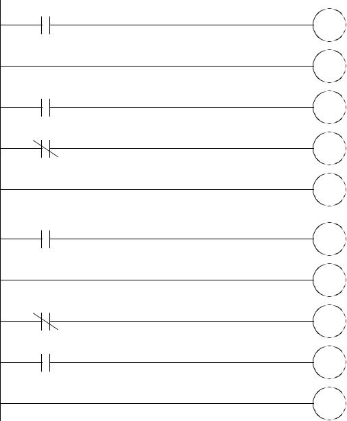
The ladder logic for operation F2 is simple, and when the start button is pushed, it will turn off F2 and turn on F3. The ladder logic for operation F3 opens the inlet valve and moves to operation F4.
plc flowchart - 11.9
F2
MCR
start
F2
U
F3
L
MCR
F3
MCR
outlet
U
inlet
L
F3
U
F4
L
MCR
Figure 11.7 Ladder Logic for Flowchart Operations F2 and F3
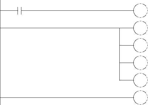
The ladder logic for operation F4 turns off F4, and if the tank is full it turns on F6, otherwise F5 is turned on. The ladder logic for operation F5 is very similar.
plc flowchart - 11.10
F4 |
|
|
MCR |
|
|
U |
F4 |
|
|
||
tank full |
F6 |
|
L |
||
|
||
tank full |
F5 |
|
L |
||
|
||
MCR |
|
|
F5 |
|
|
MCR |
|
|
U |
F5 |
|
|
||
stop |
F6 |
|
L |
||
|
||
stop |
F4 |
|
L |
||
|
||
MCR |
|
Figure 11.8 Ladder Logic for Operations F4 and F5
The ladder logic for operation F6 turns the outlet valve on and turns off the inlet valve. It then ends operation F6 and returns to operation F2.