

1194 |
CHAPTER 16. FOUNDATION FIELDBUS INSTRUMENTATION |
16.5.3Calibration and ranging
Calibration and ranging for a FF device is similar in principle to any other “smart” measurement instrument. Unlike analog instruments, where the “zero” and “span” adjustments completely define the instrument’s calibration and range, calibration and ranging are two completely di erent functions in a digital instrument.
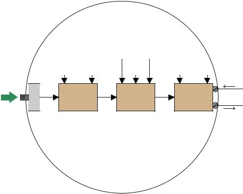
To begin, we will examine a block diagram of an analog pressure transmitter showing the zero and span adjustments, with analog signaling between all functions inside the transmitter:
Analog pressure transmitter
Calibration adjustments
Damping Zero Span
Apply pressure here
 Sensor


|
|
(Bias) |
(Gain) |
|
|
|
Low-pass |
|
|
Driver |
4-20 mA |
|
filter |
Amplifier |
|
||
|
|
circuit |
|||
analog |
circuit |
analog |
analog |
analog |
|
|
|
|
|
|
The “zero” and “span” adjustments together define the mathematical relationship between sensed pressure and current output. Calibration of an analog transmitter consists of applying known (reference standard) input stimuli to the instrument, and adjusting the “zero” and “span” settings until the desired current output values are achieved. The goal in doing this is to ensure accuracy of measurement.
The “range” of a transmitter is simply the input values associated with 0% and 100% output signals (e.g. 4 mA and 20 mA). Ranging an analog transmitter consists (also) of adjusting the “zero” and “span” settings until the output signal corresponds to the desired LRV and URV points of the measured variable. For an analog transmitter, the functions of ranging and calibration are always performed by the technician at the same time: to calibrate an analog transmitter is to range it, and vice-versa.
16.5. H1 FF DEVICE CONFIGURATION AND COMMISSIONING |
1195 |
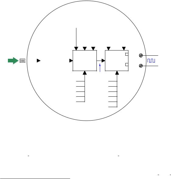
By contrast, a “smart” (digital) transmitter equipped with an analog 4-20 mA current output distinctly separates the calibration and range functions, each function determined by a di erent set of adjustments:
"Smart" pressure transmitter
Apply pressure here
 Sensor


|
|
|
Range adjustments |
|
|
|
|||
|
|
|
|
LRV |
URV |
|
|
|
|
Trim adjustments |
|
|
Trim adjustments |
|
|||||
|
Low |
High |
|
Damping |
|
Low |
High |
|
|
|
Analog-to- |
PV |
Micro- |
AO |
Digital-to |
|
|||
|
Digital |
|
|
|
Analog |
4-20 mA |
|||
|
|
|
processor digital |
||||||
analog |
Converter |
digital |
Converter |
analog |
|||||
|
|
|
|
|
|
||||
|
(ADC) |
|
|
|
|
|
|
(DAC) |
|
Calibration of a “smart” transmitter consists of applying known (reference standard) input stimuli to the instrument and engaging the “trim” functions until the instrument accurately registers the input stimuli. For a “smart” transmitter equipped with analog electronic (4-20 mA) output, there are two sets of calibration trim adjustments: one for the analog-to-digital converter and another for the digital-to-analog converter.
Ranging, by contrast, establishes the mathematical relationship between the measured input value and the output current value. To illustrate the di erence between calibration and ranging, consider a case where a pressure transmitter is used to measure water pressure in a pipe. Suppose the transmitter’s pressure range of 0 to 100 PSI translates to a 4-20 mA output current. If we desired to re-range an analog transmitter to measure a greater span of pressures (say, 0 to 150 PSI), we would have to re-apply known pressures of 0 PSI and 150 PSI while adjusting the zero and span potentiometers so 0 PSI input gave a 4 mA output value and 150 PSI input gave a 20 mA output value. The only way to re-range an analog transmitter is to completely re-calibrate it.
In a “smart” (digital) measuring instrument, however, calibration against a known (standard) source need only be done at the specified intervals to ensure accuracy over long periods of time
1196 |
CHAPTER 16. FOUNDATION FIELDBUS INSTRUMENTATION |
given the instrument’s inevitable drift. If our hypothetical transmitter were recently calibrated against a known pressure standard and trusted not to have drifted since the last calibration cycle, we could re-range it by simply changing the URV (upper range value) so that an applied pressure of 150 PSI now commands it to output 20 mA instead of an applied pressure of 100 PSI as was required before. Digital instrumentation allows us to re-range without re-calibrating, representing a tremendous savings in technician time and e ort.
The distinction between calibration and ranging tends to confuse people, even some experienced technicians. When working with an analog transmitter, you cannot calibrate without setting the instrument’s range as well: the two functions are merged in the same procedures of adjusting zero and span. When working with a digital transmitter, however, the function of calibration and the function of ranging are entirely separate.
For a detailed analogy explaining the distinction between calibration and ranging, refer to section 18.6 beginning on page 1279.
16.5. H1 FF DEVICE CONFIGURATION AND COMMISSIONING |
1197 |
Fieldbus instruments, of course, are “smart” in the same way, and their internal block diagrams look much the same as the “smart” transmitters with analog current output, albeit with a far greater number of parameters within each block. The rectangle labeled “XD” in the following diagram is the Transducer block, while the rectangle labeled “AI” is the Analog Input block:
FF pressure transmitter
Trim adjustments
Cal_Point_Lo Cal_Point_Hi
|
|
Range adjustments |
||
|
|
XD_Scale OUT_Scale |
||
Damping |
(0% to 100%) (0% to 100%) |
|||
|
|
|
|
|
|
|
|
|
|
|
|
|
|
|
Apply pressure |
|
|
|
|
|
|
here |
Sensor |
|
|
Analog-to- |
|
|
|
|
|
|
Converter |
|
|
|
|
|
|
|
Digital |
|
|
|
|
|
|
|
|
|
|
|
|
|
(ADC) |
|
Cal_Unit
Sensor_Range
Sensor_Cal_Date
Sensor_Cal_Who
etc.
XD AI
Primary_Value
Channel
L_Type
PV_Ftime
Lo_Alm
Hi_Alm
etc.
OUT_D |
|
OUT |
FF data |
Calibration (trim) values are set in the transducer block along with the engineering unit, making the output of the transducer block a digital value scaled in real units of measurement (e.g. PSI, kPa, bar, mm Hg, etc.) rather than an abstract ADC “count” value. The analog input function block’s Channel parameter tells it which transducer output to receive22 as the pre-scaled “Primary Value”, which it may then translate to another scaled value based on a proportionality between transducer scale values (XD Scale high and low) and output scale values (OUT Scale high and low).
To calibrate such a transmitter, the transducer block should first be placed in Out Of Service (OOS) mode using a handheld FF communicator or the Fieldbus host system. Next, a standard (calibration-grade) fluid pressure is applied to the transmitter’s sensor and the Cal Point Lo
22Fieldbus transmitters often have multiple channels of measurement data to select from. For example, the multivariable Rosemount 3095MV transmitter assigns channel 1 as di erential pressure, channel 2 as static pressure, channel 3 as process temperature, channel 4 as sensor temperature, and channel 5 as calculated mass flow. Setting the Channel parameter properly in the AI block is therefore critical for linking it to the proper measurement variable.

1198 |
CHAPTER 16. FOUNDATION FIELDBUS INSTRUMENTATION |
parameter is set to equal this applied pressure. After that, a greater pressure is applied to the sensor and the Cal Point Hi parameter is set to equal this applied pressure. After setting the various calibration record-keeping parameters (e.g. Sensor Cal Date, Sensor Cal Who), the transducer block’s mode may be returned to Auto and the transmitter used once again.
To range such a transmitter, a correspondence between sensed pressure and the process variable must be determined and entered into the analog input function block’s XD Scale and OUT Scale parameters. If the pressure transmitter is being used to indirectly measure something other than pressure, these range parameters will become very useful, not only proportioning the numerical values of the measurement, but also casting the final digital output value into the desired “engineering units” (units of measurement).
Ranging in Fieldbus transmitters is a somewhat confusing topic due to the unfortunate names given to the di erent L Type parameter options. Here is a list of the L Type parameter options along with their meanings:
•Direct = the AI block will publish the signal output by the XD block, regardless of the specified
OUT Scale range
•Indirect = the AI block will mathematically scale the signal from the XD block into a range
specified by OUT Scale parameters using a linear equation (e.g. y = mx + b)
•Indirect square root = same as above, except that a square-root function is applied to the percentage of range (useful when characterizing flow transmitters based on di erential pressure measurement)
The terms “direct” and “indirect” are unfortunate23, because they often cause people to interpret them as “direct” and “reverse” (as though L Type described the direction of action for the function block). This is not what these terms mean for the AI block! What a “direct” value for L Type means is that the raw value of the XD block is what will be published onto the Fieldbus network by the AI block. What an “indirect” value for L Type means is that the XD block’s signal will be scaled to a di erent range (specified by the OUT Scale parameter). In summary, the technician must set the XD Scale range according to the primary signal sensed by the transmitter’s sensing element, and set the OUT Scale range according to what the rest of the control system needs to see proportional to that primary signal.
23If I were king for a day, I would change the labels “direct” and “indirect” to “raw” and “scaled”, respectively. Alternatively, I would abandon the “direct” option altogether, because even when this option is chosen the OUT Scale range still exists and may contain “scaled” values even though these are ignored in “direct” mode!
16.5. H1 FF DEVICE CONFIGURATION AND COMMISSIONING |
1199 |
The concept of ranging a FF transmitter makes more sense when viewed in the context of a real application. Consider this example, where a pressure transmitter is being used to measure the level of ethanol (ethyl alcohol) stored in a 40 foot high tank. The transmitter connects to the bottom of the tank by a tube, and is situated 10 feet below the tank bottom:
(vent)
100% |
|
|
|
|
|
|
|
|
|
|
|
|
|
|
|
|
|
|
|
|
|
|
|
|
|
|
|
|
|
|
|
|
|
|
|
Measurement |
|
|
|
|
|
|
|
|
|
|
|
|
|
|
|
||
|
|
|
|
|
|
|
|
|
|
|
|
|
|
||||
span = 40 ft |
Ethanol |
FF level |
|||||||||||||||
|
|
|
|
|
|||||||||||||
|
|
|
|
|
γ = 49.3 lb/ft3 |
||||||||||||
|
|
|
|
|
transmitter |
||||||||||||
0% |
|
|
|
|
|
|
|
|
|
|
|
|
|
|
|
|
|
|
|
|
|
|
|
|
|
|
|
|
|
|
|
|
|
|
|
|
|
|
|
|
10 ft |
|
|
|
|
|
|
|
|
|
|
||
|
|
|
|
|
|
|
|
|
H |
|
|
|
L |
|
|||
|
|
|
|
|
|
|
|
|
|
|
|
|
|
|
|
|
|
|
|
|
|
|
|
|
|
|
|
|
|
|
|
|
|
|
|
Hydrostatic pressure exerted on the transmitter’s sensing element is the product of liquid density (γ) and vertical liquid column height (h). When the tank is empty, there will still be a vertical column of ethanol 10 feet high applying pressure to the transmitter’s “high” pressure port. Therefore, the pressure seen by the transmitter in an “empty” condition is equal to:
Pempty = γhempty = (49.3 lb/ft3)(10 ft)
Pempty = 493 lb/ft2 = 3.424 PSI
When the tank is completely full (40 feet), the transmitter sees a vertical column of ethanol 50 feet high (the tank’s 40 foot height plus the suppression height of 10 feet created by the transmitter’s location below the tank bottom). Therefore, the pressure seen by the transmitter in a “full” condition is equal to:
Pf ull = γhf ull = (49.3 lb/ft3)(40 ft + 10 ft)
Pf ull = 2465 lb/ft2 = 17.12 PSI
Thus, the transducer (XD) block in this Fieldbus transmitter will sense a liquid pressure ranging from 3.424 PSI to 17.12 PSI over the full range of the tank’s storage capacity.

1200 |
CHAPTER 16. FOUNDATION FIELDBUS INSTRUMENTATION |
However, we do not want this transmitter to publish a signal to the Fieldbus network in units of PSI, because the operations personnel monitoring this control system want to see a measurement of ethanol level inside the tank, not hydrostatic pressure at the bottom of the tank. We may be exploiting the principle of hydrostatic pressure to sense ethanol level, but we do not wish to report this measurement as a pressure.
The proper solution for this application is to set the L Type parameter to “indirect” which will instruct the AI function block to mathematically scale the XD block’s pressure signal into a di erent range. Then, we must specify24 the expected pressure range and its corresponding level range as XD Scale and OUT Scale, respectively25:
AI block parameter |
Range values |
||||
|
|
|
|
|
|
L |
|
Type |
Indirect |
||
|
|
|
|
|
|
XD |
|
|
Scale |
3.424 PSI to 17.12 PSI |
|
|
|
|
|
||
OUT |
|
Scale |
0 feet to 40 feet |
||
|
|
|
|
|
|
Now, the ethanol tank’s level will be accurately represented by the FF transmitter’s output, both in numeric value and measurement unit. An empty tank generating a pressure of 3.424 PSI causes the transmitter to output a “0 feet” digital signal value, while a full tank generating 17.12 PSI of pressure causes the transmitter to output a “40 feet” digital signal value. Any ethanol levels between 0 and 40 feet will likewise be represented proportionally by the transmitter.
If at some later time the decision is made to re-locate the transmitter so it no longer has a 10 foot “suppression” with regard to the tank bottom, the XD Scale parameters may be adjusted to reflect the corresponding shift in pressure range, and the transmitter will still accurately represent ethanol level from 0 feet to 40 feet, without re-calibrating or re-configuring anything else in the transmitter.
If we wished, we could even mathematically determine the liquid volume stored inside this ethanol tank at di erent sensed pressures, and then scale the AI block’s OUT Scale parameter to report a volume in units of gallons, liters, cubic feet, or any other appropriate volume unit. Using the “indirect” mode with appropriate XD Scale and OUT Scale parameter values gives us great flexibility in how the transmitter senses and represents process data.
In summary, we set the XD Scale parameter to the physical range of measurement directly sensed by the transducer, we set the OUT Scale parameter to the corresponding range of measurement we wish the transmitter to report to the rest of the control system, and we set L Type to “indirect” to enable this translation from one range to another. We should only use the “direct” L Type setting if the raw transducer range is appropriate to output to the rest of the control system (e.g. if the transmitter directly senses fluid pressure and we wish this very same pressure value to be published onto the Fieldbus network by the transmitter, with no scaling).
24It is important to note that you must correctly calculate the corresponding XD Scale and OUT Scale parameter values in order for this to work. The Fieldbus instrument does not calculate the parameters for you, because it does not “know” how many PSI correspond to how many feet of liquid level in the tank. These values must be calculated by some knowledgeable human technician or engineer and then entered into the instrument’s AI block, after which the instrument will execute the specified scaling as a purely mathematical function.
25When configuring the XD Scale high and low range values, be sure to maintain consistency with the transducer block’s Primary Value Range parameter unit. Errors may result from mis-matched measurement units between the transducer block’s measurement channel and the analog input block’s XD Scale parameter.

16.5. H1 FF DEVICE CONFIGURATION AND COMMISSIONING |
1201 |
Here is another Fieldbus transmitter ranging application, this time a di erential pressure transmitter sensing pressure dropped across an orifice plate in order to infer the rate of flow for fluid inside the pipe. The transmitter senses small amounts of pressure di erence (expressed in a unit of pressure called inches water column), but what we want it to report to the Fieldbus network is an actual flow rate in gallons per minute.
If we happen to know that this orifice plate produces a pressure drop of 125 inches water column (125 ”WC) at a flow rate of 350 gallons per minute (350 GPM), we could set up the scaling parameters as shown:
|
|
|
|
FT |
|
|
|
|
|
Fieldbus |
|
|
|
|
|
Published signal = |
||||||||
|
|
|
|
|
|
|
|
|
|
|
|
|
|
|
|
|
|
|
||||||
|
|
|
|
|
|
|
|
|
|
|
|
|
|
|
|
|
0 to 350 GPM |
|||||||
|
|
|
|
|
|
|
|
|
|
|
|
|
|
|
|
|||||||||
|
|
|
|
|
|
|
|
|
|
|
|
|
|
|
|
|
|
|
|
|
|
|
||
|
|
|
|
|
|
|
|
|
|
|
|
|
|
|
|
|
|
|
|
|
|
|
||
|
|
|
|
|
|
|
|
|
|
|
|
|
|
|
|
|
|
|
|
|
|
|
|
|
H |
|
|
L |
|
|
|
|
|
|
|
|
|
|
|
|
|||||||||
|
|
|
|
|
|
|
|
|
|
|
|
Pressure drop = P = |
||||||||||||
|
|
|
|
|
|
|
|
|
|
|
|
|||||||||||||
|
|
|
|
|
|
|
|
|||||||||||||||||
|
|
|
|
|
|
|
|
|
|
|
|
|
|
|
0 to 125 "W.C. |
|||||||||
|
|
|
|
|
|
|
|
|
|
|
|
|
|
|||||||||||
|
|
|
|
|
|
|
|
|
|
|
|
|
||||||||||||
|
|
|
|
|
|
|
|
|
|
|
|
|
|
|
|
|
|
|
|
|
|
|
|
|
|
|
|
|
|
|
|
|
|
|
|
|
|
|
|
|
|
|
|
|
|
|
|
|
|
|
|
|
|
|
|
|
|
|
Flow (Q) |
|
|
|
|
|
|
|
||||||||
|
|
|
|
|
|
|
|
|
|
|
|
|
|
|
|
|||||||||
|
|
|
|
|
|
|
|
|
|
|
|
|
|
|
|
|
|
|
|
|
|
|
|
|
|
|
|
|
|
|
|
|
|
|
|
|
|
|
|
|
|
|
|
|
|
|
|
|
|
|
Orifice plate |
|
|
|
|
|
|
|
|
|
|
|
|
|||||||||||
|
|
|
|
|
|
|
|
|
|
|
|
|||||||||||||
|
AI block parameter |
|
|
|
|
|
|
|
Range values |
|
||||||||||||||
|
|
|
|
|
|
|
|
|
|
|
|
|||||||||||||
|
|
|
L |
Type |
|
|
|
|
|
Indirect Square Root |
|
|||||||||||||
|
|
|
|
|
|
|
|
|
||||||||||||||||
|
|
XD |
Scale |
|
|
|
0 inches water to 125 inches water |
|
||||||||||||||||
|
|
|
|
|
|
|||||||||||||||||||
|
|
|
|
|
|
|
|
|
|
|
||||||||||||||
|
|
OUT |
Scale |
|
|
|
|
|
0 GPM to 350 GPM |
|
||||||||||||||
|
|
|
|
|
|
|
|
|||||||||||||||||
Note the use of the “indirect square root” L Type parameter value instead of just “indirect” as we used in the ethanol tank example. The square root function is necessary in this application because the relationship between di erential pressure (ΔP ) and flow rate (Q) through an orifice is nonlinear, as described by the following formula:
√
Q = k P
This particular nonlinearity is unique to pressure-based measurements of fluid flow, and does not find application in any other form of process measurement.
As before, though, we see a common theme with the XD Scale and OUT Scale parameter ranges: we set the XD Scale parameter to the physical range of measurement directly sensed by the transducer, we set the OUT Scale parameter to the corresponding range of measurement we wish the transmitter to report to the rest of the control system, and we set L Type to “indirect” to enable this translation from one range to another.