

Chapter 19
Continuous pressure measurement
In many ways, pressure is the primary variable for a wide range of process measurements. Many types of industrial measurements are actually inferred from pressure, such as:
•Flow (measuring the pressure dropped across a restriction)
•Liquid level (measuring the pressure created by a vertical liquid column)
•Liquid density (measuring the pressure di erence across a fixed-height liquid column)
•Weight (hydraulic load cell)
Even temperature may be inferred from pressure measurement, as in the case of a fluid-filled chamber where fluid pressure and fluid temperature are directly related. As such, pressure is a very important quantity to measure, and measure accurately. This section describes di erent technologies for the measurement of pressure.
1311
1312 CHAPTER 19. CONTINUOUS PRESSURE MEASUREMENT
19.1 Manometers
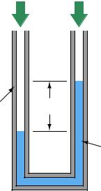
A very simple device used to measure pressure is the manometer : a fluid-filled tube where an applied gas pressure causes the fluid height to shift proportionately. This is why pressure is often measured in units of liquid height (e.g. inches of water, inches of mercury). As you can see, a manometer is fundamentally an instrument of di erential pressure measurement, indicating the di erence between two pressures by a shift in liquid column height:
|
U-tube manometer |
||||||||
Applied |
|
|
|
|
|
|
|
|
Applied |
pressure |
|
|
|
|
|
|
|
|
pressure |
(greater) |
|
|
|
|
|
|
|
|
(lesser) |
Transparent Head tube allows
liquid columns to be seen
Liquid
Of course, it is entirely acceptable to simply vent one tube of a manometer and use it as a gauge pressure instrument, comparing the applied pressure at one tube against atmospheric pressure in the other.
19.1. MANOMETERS |
1313 |
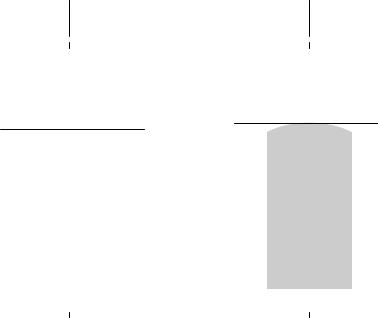
Liquid column height in a manometer should always be interpreted at the centerline of the liquid column, regardless of the shape of the liquid’s meniscus (the curved air/liquid interface):
|
|
Read here |
|
|
|
|
|
|
|
|
|
|
|
|
|
|
|
|
|
|
|
|
|
|
|
|
|
|
|
|
|
Read here |
|
|
|
C |
|
C |
|
|
|
|||
|
|
|
||
|
|
|
||
|
|
|
||
|
L |
|
|
L |
|
|
|
|
|
|
|
|
|
|
|
|
|
|
|
|
|
|
|
|
|
|
|
|
|
|
|
|
|
|
|
|
|
|
|
|
|
|
|
|
1314 |
CHAPTER 19. CONTINUOUS PRESSURE MEASUREMENT |
Manometers come in a variety of forms, the most common being the U-tube, well (sometimes called a cistern), raised well, and inclined :
U-tube manometer |
"Well" manometer |
(vented) |
(vented) |
Applied |
Applied |
pressure |
|
|
pressure |
|
Well |
|
|
|
|
|
|
|
|
|
|
"Raised-well" inclined manometer |
Pressure |
||||||||
"Raised well" manometer |
input |
||||||||||||||||||
|
(vented) |
|
|
||||||||||||||||
|
|
|
|
|
|
|
|
|
|
|
|
|
|||||||
|
|
|
|
|
|
|
|
|
|
|
|
|
|
|
|
|
|
|
|
|
|
|
|
|
|
|
|
|
|
|
|
|
|
|
|
|
|
|
|
|
|
|
|
|
|
|
|
|
|
|
|
|
|
|
|
|
|
|
|
|
|
|
|
|
|
|
|
|
|
|
|
|
|
|
|
|
|
|
|
Well |
|
|
|
|
|
|
|
Well |
|
|
|
|
|||||||
|
|
|
|
|
|
||||||||||||||
|
|
|
|
|
|
||||||||||||||
|
|
|
|
|
|
|
|
|
|
|
|
|
|
|
|
|
|
|
|
|
|
|
|
|
|
|
|
|
|
|
|
|
|
|
|
|
|
|
|
|
|
|
|
|
|
|
|
|
|
|
|
|
|
|
|
|
|
|
|
|
|
|
|
|
|
|
|
|
|
|
|
|
|
|
|
|
|
|
|
|
|
|
|
|
|
|
|
|
|
|
|
|
|
|
|
|
|
|
|
|
|
|
|
|
|
|
|
|
|
|
|
|
|
|
|
|
|
|
|
|
|
|
|
|
|
|
|
|
|
|
|
|
|
|
|
|
|
|
|
|
|
|
|
|
|
|
|
|
|
|
|
|
|
|
|
|
|
|
|
|
|
|
|
|
|
|
|
|
|
|
|
|
|
|
|
|
|
|
|
|
|
|
|
|
|
|
|
|
|
|
|
|
|
|
|
|
|
|
|
|
|
|
|
|
|
|
|
|
|
|
|
|
|
|
|
|
|
|
|
|
|
|
|
|
|
|
|
|
|
|
|
|
|
|
|
|
|
|
|
|
|
|
|
|
|
|
|
|
|
|
|
|
|
|
|
|
|
|
|
|
|
|
|
|
|
|
|
|
|
|
|
|
|
|
|
|
|
|
|
|
|
|
|
|
|
|
|
|
|
|
|
|
|
|
|
|
|
|
|
|
|
|
|
|
|
|
|
|
|
|
|
|
|
|
|
|
|
|
|
|
|
|
|
|
|
|
|
|
|
|
|
|
|
|
|
|
|
|
|
|
|
|
|
|
|
|
|
|
|
|
|
|
|
|
|
|
|
|
|
|
|
|
|
|
|
|
|
|
|
|
|
|
|
|
|
|
|
|
|
|
|
|
|
|
|
|
|
|
|
|
|
|
|
|
|
|
|
|
|
|
|
|
|
|
|
|
|
|
|
|
|
|
|
|
|
|
|
|
|
|
|
|
|
|
|
|
|
|
|
|
|
|
|
|
|
|
|
|
|
|
|
|
|
|
|
|
|
|
|
|
|
|
|
|
|
|
|
|
|
|
|
|
|
|
|
|
|
|
|
|
|
|
|
|
|
|
|
|
|
|
|
|
|
|
|
|
|
|
|
|
|
|
|
|
|
|
|
|
|
|
|
|
|
|
|
|
|
|
|
|
|
|
|
|
|
|
|
|
|
19.1. MANOMETERS |
1315 |
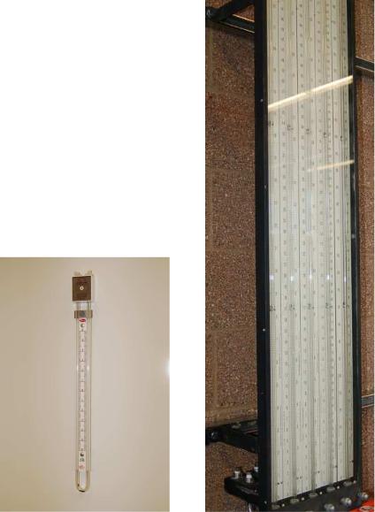
U-tube manometers are very inexpensive, and are generally made from clear plastic (see the lefthand photo). Cistern-style manometers are the norm for calibration bench work, and are typically constructed from metal cisterns and glass tubes (see the right-hand photo):
1316 |
CHAPTER 19. CONTINUOUS PRESSURE MEASUREMENT |
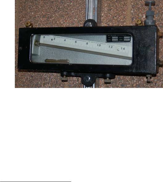
Inclined manometers are used to measure very low pressures, owing to their exceptional sensitivity (note the fractional scale for inches of water column in the following photograph, extending from 0 to 1.5 inches on the scale, reading left to right):
Note that venting one side of a manometer is standard practice when using it as a gauge pressure indicator (responding to pressure in excess of atmospheric). Both pressure ports will be used if the manometer is applied to the measurement of di erential pressure, just as in the case of the U-tube manometer first shown in this section. Absolute pressure may also be measured by a manometer, if one of the pressure ports connects to a sealed vacuum chamber. This is how a mercury barometer is constructed for the measurement of absolute ambient air pressure: by sealing o one side of a manometer and removing all the air in that side, such that the applied (atmospheric) pressure is always compared against a vacuum.
Manometers incorporating a “well” have the advantage of single-point reading: one need only compare the height of one liquid column, not the di erence in height between two liquid columns. The cross-sectional area of the liquid column in the well is so much greater than that within the transparent manometer tube that the change in height within the well is usually negligible. In cases where the di erence is significant, the spacing between divisions on the manometer scale may be skewed to compensate1.
Inclined manometers enjoy the advantage of increased sensitivity. Since manometers fundamentally operate on the principle of pressure balanced by liquid height, and this liquid height is always measured parallel to the line of gravitational pull (perfectly vertical), inclining the manometer tube means that liquid must travel farther along the tube to generate the same change in (purely)
1If you are having di culty understanding this concept, imagine a simple U-tube manometer where one of the tubes is opaque, and therefore one of the two liquid columns cannot be seen. In order to be able to measure pressure just by looking at one liquid column height, we would have to make a custom scale where every inch of height registered as two inches of water column pressure, because for each inch of height change in the liquid column we can see, the liquid column we can’t see also changes by an inch. A scale custom-made for a well-type manometer is just the same concept, only without such dramatic skewing of scales.
19.1. MANOMETERS |
1317 |
vertical height than it would in a vertical manometer tube. Thus, an inclined manometer tube causes an amplification in liquid motion for a given amount of pressure change, allowing measurements of greater resolution.