


19.5. DIFFERENTIAL PRESSURE TRANSMITTERS |
1345 |
into motion (displacement) which is sensed and converted into an electronic signal, a force-balance transmitter works best when the diaphragm is slack and has no spring characteristics at all. Balance with the force of the process fluid pressure is achieved by the application of either an adjustable air pressure or an adjustable electric current, not by the natural tensing of a spring element. This makes a force-balance instrument far less susceptible to errors due to metal fatigue or any other degradation of spring characteristics.
Unfortunately, force-balance instruments have significant disadvantages as well. Force-balance mechanisms tend to be bulky11, and they translate external vibration into inertial force which adds “noise” to the output signal. Also, the amount of electrical power necessary to provide adequate balancing force in an electronic force-balance transmitter is such that it is nearly impossible to limit below the level necessary to ensure intrinsic safety (protection against the accidental ignition of explosive atmospheres by limiting the amount of energy the instrument could possibly discharge into a spark).
19.5Di erential pressure transmitters
One of the most common, and most useful, pressure measuring instruments in industry is the di erential pressure transmitter. This device senses the di erence in pressure between two ports and outputs a signal representing that pressure in relation to a calibrated range. Di erential pressure transmitters may be based on any of the previously discussed pressure-sensing technologies, so this section focuses on application rather than theory.
11One instrument technician I know referred to the Foxboro E13 di erential pressure transmitter as “pig iron” after having to hoist it by hand to the top of a distillation column.
1346 |
CHAPTER 19. CONTINUOUS PRESSURE MEASUREMENT |
19.5.1DP transmitter construction and behavior
Di erential pressure transmitters constructed for industrial measurement applications typically consist of a strong (forged metal) body housing the sensing element(s), topped by a compartment housing the mechanical and/or electronic components necessary to translate the sensed pressure into a standard instrumentation signal (e.g. 3-15 PSI, 4-20 mA, digital fieldbus codes):
Pneumatic DP |
Electronic DP |
transmitter |
transmitter |
Force-balance
mechanism
|
Wires |
|
Air signal out |
Electronics |
|
Air supply |
||
|
H |
L |
H |
L |
Diaphragm capsule |
Diaphragm capsule |
assembly |
assembly |
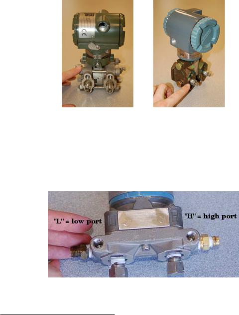
Two models of electronic di erential pressure transmitter appear in the following photographs, the Rosemount model 1151 (left) and model 3051 (right):
19.5. DIFFERENTIAL PRESSURE TRANSMITTERS |
1347 |
Two more models of electronic di erential pressure transmitter are shown in the next photograph, the Yokogawa EJA110 (left) and the Foxboro IDP10 (right):
In each of these di erential pressure transmitter examples, the pressure-sensing element is housed in the bottom half of the device (the forged-steel structure) while the electronics are housed in the top half (the colored, round, cast-aluminum structure).
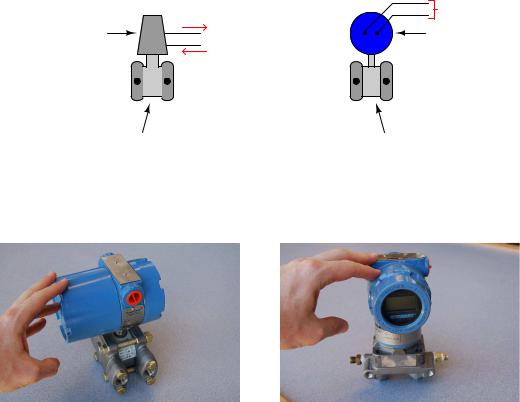
Regardless of make or model, every di erential pressure (“DP”, “d/p”, or ΔP)12 transmitter has two pressure ports to sense di erent process fluid pressures. These ports typically have 14 inch female NPT threads for convenient connection to the process. One of these ports is labeled “high” and the other is labeled “low”. This labeling does not necessarily mean that the “high” port must always be at a greater pressure than the “low” port. What these labels represent is the e ect any increasing fluid pressure applied to that port will have on the direction of the output signal’s change.
12As far as I have been able to determine, the labels “D/P” and “DP cell” were originally trademarks of the Foxboro Company. Those particular transmitter models became so popular that the term “DP cell” came to be applied to nearly all makes and models of di erential pressure transmitter, much like the trademark “Vise-Grip” is often used to describe any self-locking pliers, or “Band-Aid” is often used to describe any form of self-adhesive bandage.
1348 |
CHAPTER 19. CONTINUOUS PRESSURE MEASUREMENT |
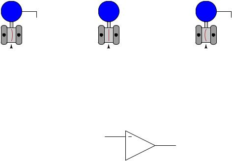
The most common sensing element used by modern DP transmitters is the diaphragm. One side of this diaphragm receives process fluid pressure from the “high” port, while the other receives process fluid pressure from the “low” port. Any di erence of pressure between the two ports causes the diaphragm to flex from its normal resting (center) position. This flexing is then translated into an output signal by any number of di erent technologies, depending on the manufacturer and model of the transmitter:
|
Signal increases |
|
|
|
Signal decreases |
H |
L |
H |
L |
H |
L |
|
|
|
|
|
|
|
|
|
|
|
|
|
|
|
|
|
|
|
|
|
|
|
|
|
|
|
|
|
|
|
|
|
|
|
|
|
|
|
|
|
|
|
|
|
Diaphragm flexes |
|
|
Diaphragm in |
|
|
Diaphragm flexes |
|
|||||||||||||
|
|
to the right |
|
|
|
resting position |
|
|
|
to the left |
|
|
|||||||||
|
|
|
|
|
|
|
|
|
|
|
|
|
|
|
|
|
|
|
|
|
|
Phigh |
> |
|
|
Plow |
Equal pressures applied |
Phigh |
< |
|
|
Plow |
|||||||||||
|
|
|
|
|
|
|
|
to "high" and "low" ports |
|
|
|
|
|
|
|
|
|||||
The concept of di erential pressure instrument port labeling is very similar to the “inverting” and “noninverting” labels applied to operational amplifier input terminals:
Inverting
Noninverting 

The “+” and “−” symbols do not imply polarity of the input voltage(s); i.e. it is not as though the “+” input must be more positive than the “−” input. These symbols merely represent the di erent direction each input tends to drive the output signal. An increasing potential applied to the “+” input drives the opamp’s output positive, while an increasing potential applied to the “−” input drives the opamp’s output negative. Phrasing this in terms common to closed-loop control systems, we could say that the “+” input is direct-acting while the “−” input is reverse-acting.

19.5. DIFFERENTIAL PRESSURE TRANSMITTERS |
1349 |
Similarly, the “H” and “L” labels on a DP transmitter’s ports do not imply magnitude of input pressures; i.e. it is not as though the “H” port’s pressure must be greater than the “L” port’s pressure. These symbols merely represent the di erent e ects on the output signal resulting from pressure applied to each port. An increasing pressure applied to the “high” port of a DP transmitter will drive the output signal to a greater level (up), while an increasing pressure applied to the “low” port of a DP transmitter will drive the output signal to a lesser level (down)13:
Pressure here drives output  toward 20 mA
(flexes diaphragm to the right)
|
4-20 mA signal |
|
H |
L |
Pressure here |
|
|
drives output |
|
|
toward 4 mA |
High |
Low |
(flexes diaphragm to the left) |
|
||
side |
side |
|
The ability to arbitrarily connect a DP transmitter to a process in such a way that it is either direct-acting or reverse-acting is a great advantage, as we will later see.
In the world of electronics, we refer to the ability of a di erential voltage sensor (such as an operational amplifier) to sense small di erences in voltage while ignoring large potentials measured with reference to ground by the phrase common-mode rejection. An ideal operational amplifier completely ignores the amount of voltage common to both input terminals, responding only to the di erence in voltage between those terminals. This is precisely what a well-designed DP instrument does, except with fluid pressure instead of electrical voltage. A DP instrument ignores gauge pressure common to both ports, while responding only to di erences in pressure between those two ports. Stated in other words, a di erential pressure instrument (ideally14) responds only to di erential pressure while ignoring common-mode pressure.
13One transmitter manufacturer I am aware of (ABB/Bailey) actually does use the “+” and “−” labels to denote highand low-pressure ports rather than the more customary “H” and “L” labels found on other manufacturers’ DP products.
14Perfect common-mode rejection is impossible for di erential pressure instruments just as it is impossible for electronic voltage-measuring instruments, but in either case the e ect is usually minimal. For di erential pressure transmitters, the e ect of common-mode pressure on the instrument’s output signal is sometimes referred to as the line pressure e ect or static pressure e ect, typically stated as a percentage of the instrument’s upper range limit per unit of common-mode pressure.
1350 |
CHAPTER 19. CONTINUOUS PRESSURE MEASUREMENT |
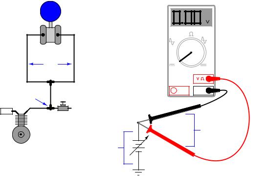
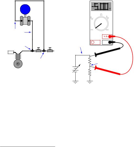
To illustrate, we may connect the “high” and “low” ports of a di erential pressure transmitter together using pipe or tube, then expose both ports simultaneously to a source of fluid pressure such as pressurized air from an air compressor. If the transmitter is in good working order, it should continue to register zero di erential pressure even as we vary the amount of static pressure applied to both ports. So long as the applied pressures to each port are equal, the transmitter’s sensing diaphragm should experience zero net force pushing left or right. All force applied to the diaphragm from the “high” port’s fluid pressure should be precisely countered (canceled) by force applied to the diaphragm from the “low” port’s fluid pressure.
An electrical analogy to this would be connecting both red and black test leads of a voltmeter to a common point in an electrical circuit, then varying the amount of voltage between that point and earth ground. Since the voltmeter only registers di erences of potential between its test leads, and those test leads are now electrically common to one another, the magnitude of common-mode voltage between that one point of the circuit and earth ground is irrelevant from the perspective of the voltmeter:
H L |
|
|
|
|
V |
|
A |
Pdifferential |
V |
|
A |
= 0 PSI |
|
||
|
|
OFF |
|
Pcommon-mode |
|
A |
COM |
= 100 PSI |
|
|
|
|
Vent |
|
|
|
|
|
Vdifferential |
|
|
|
= 0 volts |
Air compressor |
Vcommon-mode |
|
|
= 100 volts |
|
|
|
|
|
|
In each case the di erential measurement device rejects the common-mode value, registering only the amount of di erence (zero) between its sensing points.
19.5. DIFFERENTIAL PRESSURE TRANSMITTERS |
1351 |
The same common-mode rejection principle reveals itself in more complex fluid and electrical circuits. Consider the case of a DP transmitter and a voltmeter, both used to measure di erential quantities in a “divider” circuit15:
H |
L |
V |
A |
|
|
|
|
||
Pdifferential |
|
V |
A |
Vdifferential |
= -5 PSI |
|
|
OFF |
= -5 volts |
|
|
|
||
P = 100 PSI |
A |
COM |
|
|
V = 100 volts |
|
|
||
|
|
|
|
|
|
|
Vent |
|
|
|
P = 95 PSI |
|
V = 95 volts |
|
|
|
|
|
|
Air compressor |
|
|
|
|
In each case the di erential measurement device responds only to the di erence between the two measurement points, rejecting the common-mode value (97.5 PSI for the pressure transmitter, 97.5 volts for the voltmeter). Just to make things interesting in this example, the “high” side of each measuring instrument connects to the point of lesser value, such that the measured di erence is a negative quantity. Like digital voltmeters, modern DP transmitters are equally capable of accurately measuring negative pressure di erences as well as positive pressure di erences.
15The electrical circuit shown on the right uses a pair of series-connected resistors to divide the source voltage into two parts, 5 volts and 95 volts. The pneumatic circuit shown on the left uses a pair of series-connected hand valves to divide the source pressure into two parts, 5 PSI and 95 PSI.
1352 |
CHAPTER 19. CONTINUOUS PRESSURE MEASUREMENT |
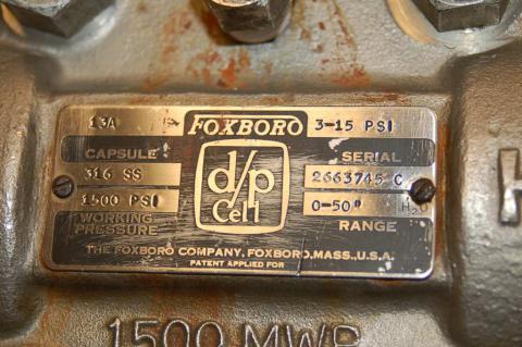
A vivid contrast between di erential pressure and common-mode pressure for a DP instrument is seen in the pressure ratings shown on the nameplate of a Foxboro model 13A di erential pressure transmitter:
This nameplate tells us that the transmitter has a calibrated di erential pressure range of 50” H2O (50 inches water column, which is only about 1.8 PSI). However, the nameplate also tells us that the transmitter has a maximum working pressure (MWP) of 1500 PSI. “Working pressure” refers to the amount of gauge pressure common to each port, not the di erential pressure between ports. Taking these figures at face value means this transmitter will register zero (no di erential pressure) even if the gauge pressure applied equally to both ports is a full 1500 PSI! In other words, this di erential pressure transmitter will reject up to 1500 PSI of common-mode gauge pressure, and respond only to small di erences in pressure between the ports (1.8 PSI di erential being enough to stimulate the transmitter to full scale output).