

3649
.pdfRussian Journal of Building Construction and Architecture
shear, hence it should be determined given the constraint (12). In this case, the shear stiffness value of over 1500 МН/m2 corresponds to the middle and upper intervals of the shear stiffness of the structures with flexible rod supports [3].
Thus, given the constraint (12), the solution (14) of the integral equation (11) allows the upper limit of shear stiffness to be determined for each concrete structure where calculations can be carried out using the classical model of flat sections, which is of great practical importance for the design and substantiation of calculation schemes.
Conclusions. Based on the numerical experiments, a new analytical formula is obtained for a single-span beam with a uniformly distributed load along the entire length, which determines the dependence of the displacement of the reinforced concrete slab over the steel beam on the shear stiffness of the joint. In actual design practice, it allows one to obtain more accurate stress distribution fields in composite structures of steel-reinforced concrete span structures of bridge structures.
The lower limit of shear stiffness is identified below which the joint should be considered absolutely yielding and the composite beam cannot be considered steel-reinforced concrete. The formula is obtained for determining the upper boundary of shear stiffness above which the classical approach is allowed to be employed for calculating steel-reinforced concrete structures assuming there is no shear.
References
1.Belutskii I. Yu. Sovershenstvovanie metodov otsenki rabotosposobnosti ekspluatiruemykh stalezhelezobetonnykh proletnykh stroenii [The development of methods to assess the health of exploited steel and concrete superstructures]. Vladivostok, Dal'nauka Publ., 2003. 280 p.
2.Belutskii I. Yu., Yatsura V. G. Otrazhenie kontseptsii I. M. Rabinovicha v kharakteristike raboty stalezhelezobetonnykh proletnykh stroenii kak sostavnykh s antagonisticheskimi svyazyami [Reflection of I. M. Rabinovich's concepts in the characterization of steel-reinforced concrete superstructures as composite structures with antagonistic connections]. Stroitel'naya mekhanika i raschet sooruzhenii, 2015, no. 5, pp. 2––8.
3.Kozlov A. V. Klassifikatsiya konstruktsii ob"edineniya zhelezobetonnoi plity so stal'nymi balkami [Classification of structures combining reinforced concrete slab with steel beams]. Stroitel'naya mekhanika i raschet sooruzhenii, 2019, no. 2 (21), pp. 50––63.
4.Kozlov A. V. Raschet stalezhelezobetonnykh mostov s uchetom sdviga plity po verkhnemu poyasu balki [Calculation of steel-reinforced concrete bridges taking into account the shift of the plate on the upper belt of the beam]. Stroitel'naya mekhanika i raschet sooruzhenii, 2018, no. 4 (19), pp. 64––71.
5.Kozlov A. V., Kuznetsova S. V. Prichiny avarii mostovykh sooruzhenii na territorii RF i stran SNG [Causes of accidents of bridge structures in Russia and CIS countries]. Dorogi i mosty, 2018, no. 39/1, pp. 204––219.
6.Korneev M. M. Stalezhelezobetonnye mosty: teoreticheskoe i prakticheskoe posobie po proektirovaniyu
[Steel-reinforced concrete bridges: a theoretical and practical guide to design]. Saint-Petersburg, FGBOU VPO PGUPS Publ., 2015. 400 p.
80
Issue № 4 (44), 2019 |
ISSN 2542-0526 |
7.Marukhin B. A. [To construction of model of work of connecting elements of steel-reinforced concrete bridges taking into account multi-cycle loading]. Novye idei novogo veka. Ch. 2 [New ideas of the new century. Part 2]. Khabarovsk, TOGU Publ., 2009, pp. 309––316.
8.ODM 218.4.027-2016 Metodicheskie rekomendatsii po opredeleniyu gruzopod"emnosti ekspluatiruemykh mostovykh sooruzhenii na avtomobil'nykh dorogakh obshchego pol'zovaniya. Metallicheskie i stalezhelezobetonnye konstruktsii [Industry road methodical document 218.4.027-2016 Guidelines for determining the load capacity of operated bridge structures on public roads. Metal and steel-reinforced concrete structures]. Moscow, Federal'noe dorozhnoe agentstvo (Rosavtodor) Publ., 2016. 127 p.
9.ODM 218.4.003-2009 Rekomendatsii po ob"edineniyu metallicheskikh balok s monolitnoi zhelezobetonnoi plitoi posredstvom nepreryvnykh grebenchatykh uporov v stalezhelezobetonnykh proletnykh stroeniyakh mostov
[Industry road methodical document 218.4.003-2009 Recommendations for combining metal beams with monolithic reinforced concrete slab by means of continuous comb stops in steel-reinforced concrete bridge spans]. Moscow, Federal'noe dorozhnoe agentstvo (Rosavtodor) Publ., 2009. 28 p.
10.Perel'muter A. V. Ispol'zovanie metodov kvadratichnogo programmirovaniya dlya rascheta sistem s odnostoronnimi svyazyami [The use of methods of quadratic programming for the calculation of systems with unilateral constraints]. Moscow, Stroiizdat Publ., 1972, no. 19, pp. 138––147.
11.Reshetnikov V. G. Novye effektivnye konstruktsii stalezhelezobetonnykh proletnykh stroenii mostov. Diss. kand. tekhn. nauk [New efficient designs of steel-reinforced concrete bridge spans. Cand. eng. sci. diss.]. Moscow, 2002. 139 p.
12.Streletskii N. N. Stalezhelezobetonnye proletnye stroeniya mostov [Steel-reinforced concrete bridge spans]. Moscow, Transport Publ., 1981, 360 p.
13.Tekhnicheskii kodeks ustanovivsheisya praktiki TKP EN 1994-2-2009 (02250) Evrokod 4. Proektirovanie stalezhelezobetonnykh konstruktsii. Chast' 2. Osnovnye printsipy i pravila dlya mostov [Technical code of established practice tap EN 1994-2-2009 (02250) Eurocode 4. Design of steel-reinforced concrete structures. Part 2. Basic principles and rules for bridges]. Minsk, 2010. 84 p.
14.Khendi Kris R., Dzhonson Rodzher P. Rukovodstvo dlya proektirovshchikov k EN 1994-2. Evrokod 4: proektirovanie stalezhelezobetonnykh konstruktsii. Chast' 2. Obshchie pravila i pravila dlya mostov [Designers ' guide to EN 1994-2. Eurocode 4: design of steel and concrete structures. Part 2. General rules and regulations for bridges]. Moscow, Izd-vo MISI-MGSU, 2014. 351 p.
15.El Sarraf R. D. Iles, Momtahan A., Easey D. and Hicks S. Steel-concrete composite bridge design guide. NZ Transport Agency research report 525, 2013. 252 p.
16.Fatigue of Stud Shear Connectors in the Negative Moment Region of Steel Girder Bridges: a Synopsis of Experimental Results and Design Recommendations. CTS 00-03, University of Minnesota, 2000.
17.KICT (Korea Institute of Construction Technology). Development of steel-concrete composite deck for highway bridges (in Korean), 2004. Report No. KICT 2004-053.
18.Oguejiofor E. C., Hosain M. U. Behavior of perfobond ribshear connectors in composite beams: full-size tests. Canadian J. of Civil Engineering, 1992, no. 19, pp. 224––235.
19.Standard Specifications of Steel and Composite Structures. JSCE, 2009.
20.Valente I., Cruz P. J. S. Experimental analysis of perfobondshear connection between steel and lightweight concrete. J. Constructional Steel Research, 2004, no. 60, pp. 465––479.
81

Russian Journal of Building Construction and Architecture
DOI 10.25987/VSTU.2019.44.4.007 UDC 6624.04
S. B. Kositsyn 1, V. S. Fedorov 2, V. Yu. Akulich 3, V. I. Kolchunov 4
NUMERICAL ANALYSIS OF A CYLINDRICAL SHELL AND SOIL CONSIDERING
CHANGES IN A COMPUTATIONAL MODEL OVER TIME
Russian University of Transport 1, 2, 3
Russia, Moscow
Southwest State Technical University 4
Russia, Kursk
1 Adviser of the RAACS, D. Sc. in Engineering, Prof. of the Dept. of Theoretical Mechanics, tel.: (499) 978-16-73, e-mail: kositsyn-s@yandex.ru
2 Academician of the RAACS, D. Sc. in Engineering, Prof. of the Dept. of Engineering Construction, Buildings and Structures, e-mail: fvs_skzs@mail.ru
3 PhD student of the Dept. of Theoretical Mechanics, e-mail: vladimir.akulich@gmail.com 4 Academician of the RAACS, D. Sc. in Engineering, Prof., tel.:+7 (910) 315-48-50
Statement of the problem. The study seeks to identify the effect of taking into account changes in the computational model over time on the stress-strain of the cylindrical shell and soil using finite elements methods.Sixcalculated caseswith avaryingnumber ofcalculated stages were compiled. The interaction of the cylindrical shell and the soil is implemented through contact pairs. Also, a calculation model is made taking into account the coefficient of friction between the cylindrical shell and the soil. Thecalculationswereperformedtakingintoaccountgeometric,physicalandcontactnonlinearities.
Results. The results of the calculations are presented in the form of diagrams of Mises stresses in the body of a cylindrical shell. The Mises stress distribution in some rings of the cylindrical shell is presented. The Mises stresses are also compared for two computational models: with and without considering the friction coefficient between the shell and the soil.
Conclusions. The obtained results showed that changes in the computational model over time significantly affect the stress-strain of the cylindrical shell and the soil. Based on the results of the six calculated cases, it is recommended that 8 or more calculated stages of the shell design should be followed in actual practical calculations. It is also found that the coefficient of friction between the cylindrical shell and the soil significantly reduces the maximum Mises stresses in the shell body.
Keywords: construction stages, finite elements method, cylindrical shell, contact finite elements.
Introduction. The construction of transport tunnels and other artificial structures is a daun-ting process that employs the methods of phased construction. Currently, in the construction of tunnels, the use of a tunneling complex fitted with an operating body for soil development is
© Kositsyn S. B., Fedorov V. S., Akulich V. Yu., Kolchunov V. I., 2019
82
Issue № 4 (44), 2019 |
ISSN 2542-0526 |
common. The complex starts moving soil is being developed. As soon as the complex has done so at a distance equal to the width of the tunnel lining ring, another ring is constructed. Thus, the cycle of work is constantly repeated: excavation –– movement of the complex –– installation of the tunnel lining ring. For the construction of the lining, a special mechanism is used, which is a block layer.
The final stress-strain following the installation of one of the tunnel lining rings is the initial state for installing the next ring. Of particular interest is the stress-strain of the tunnel following the construction of each individual shell rings well as the way internal forces are redistributed and how large these forces are.
Modern finite-element software systems enable a numerical analysis of the stress-strain of a structure being constructed with and without considering its stages of construction. Nevertheless it should be noted that the calculation models considering the stages of construction are less commonly employed in design despite better reflecting the stress-strain of the structure. The calculation considering the staged construction consists of a number of stages while applied loads and boundary conditions, as well as individual structural elements, can be removed or added to any of the stages. Such changes in applied loads, boundary conditions or state of elements are taken into account as each stage starts.
The authors of the article set out to perform a comparative analysis of the stress-strain of the shell of the transport tunnel and the surrounding soil base with and without taking into account the change in the calculation model over time by means of numerical methods. Descriptions of the resultingcomputationalmodels,conclusionsandrecommendationsontheresultsareprovided.
1. Calculation models of the shell interacting with the base taking into account and without taking into account changes in the calculation model over time. Calculation models with and without taking into account the stages of construction are designed using the ANSYS software package. The Static Structural module of the ANSYS complex is designed to solve the problems of mechanics of a deformable solid in a static setting. When employing command inserts in the APDL language, the module functionalitycan be expanded to solve, e.g., related tasks [2].
The "birth" and "death" options of the finite elements (birth and death) of the ANSYS complex enable simulation of the process of stage construction. These commands establish the finite elements which are subject to activation and deactivation in the calculation process based on some criterion, i. e., stress state, position in space, etc. Deactivation, or "death", of the finite element is caused by multiplying the stiffness of the element by a small number. The loads applied to the deactivated element are equal to zero. In addition, all the load-
83
Russian Journal of Building Construction and Architecture
transfer mechanisms through this element are temporarily reset. Once the finite element has been activated, its mass, load, and stiffness go back to their original values.
When modeling a phased construction of building structures, the following features should be considered: sometimes it is necessary to fix the displacements or other degrees of freedom of deactivated finite elements in order to avoid their excessive distortion caused by deformation of the surrounding elements of the model or free movement. With possible activation of these finite elements, artificial anchorage must be removed; activation and deactivation of elements occur instantly, which is a stepwise nonlinearity (similar to the status of contact zones), which might cause problems with the numerical convergence of the solution. This can be overcome by reducing the number of finite elements subjected to activation and deactivation at the solution stage; when considering the results, deactivated elements should be excluded in order to avoid unphysical values [2, 7, 8].
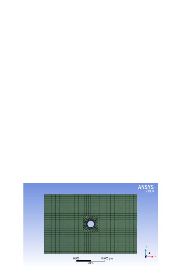
The calculation model includes a cylindrical shell (D = 3 m, shell thickness t = 0.3 m) and the surrounding base. The full width and height of the calculation model is 11D. The shell is made up of 32 individual rings 1 m wide each, the array at the installation site of the rings is also divided into 32 parts prior to activating the shell ring, part of the array is deactivated which will be replaced by the activated ring. In addition, a structural gap is set between the shell and the array which is determined by the technology of designing the shell in the foundation [18–20].
The foundation is specified by volumetric finite elements (20 nodes in each), the shell is made up of flat rectangular elements (4 nodes in each). The finite element grid of the calculation model is shown in Fig. 1 (end view).
Fig. 1. Finite-element grid of the calculation model
84

Issue № 4 (44), 2019 |
ISSN 2542-0526 |
As the foundation was being modeled, the Mora-Coulomb elastic-plastic model was adopted that the traditional soil mechanics and partially rock mechanics relied on [3, 17]. As the cylindrical shell was being modeled, a model of a perfectly elastic material was adopted. The physical and mechanical characteristics of the materials are provided in Table.
Таble
Physical and mechanical characteristics of materials
Body |
Deformation |
Poisson |
Density, kg/m3 |
modulus E, МPа |
coefficient ν |
||
|
|
|
|
Shell |
30000 |
0.2 |
2300 |
|
|
|
|
Foundation |
10 |
0.3 |
2000 |
|
|
|
|
Cohesion C, |
Angle of internal |
kPа |
friction φ, ° |
– |
|
– |
|
10 |
|
25 |
|
|
|
The external surfaces of the foundation and the edges of the shell are given boundary conditions that ensure geometric invariability and correct operation of the calculation model. Bodies are only loaded with their own weight.
When addressing the problem, the following types of nonlinearities were taken into account: geometric, physical, and contact (status change). The geometric nonlinearity is due to the significant displacements of the bodies of the computational model as they are being loaded [1, 9–10, 14]. The ANSYS software package works with the following non-linearities of a geometric nature: large deflections, large deformations, changes in effective stiffness during rotation and effective stiffness in bending. A mathematical model that considers large deflections and displacements is activated using the NLGEOM command.
The use of the Mohr-Coulomb elastic-plastic model for the foundation material defines the solution of the problem in a physically nonlinear formulation. A nonlinear relationship between the stress and strain components characterizes the operation of the foundation body material in the elastic and plastic stages of deformation. Nonlinear operation of materials can also be described using other models, e.g., various types of plasticity, creep, hyperelasticity, failure, etc. [4––6].
Contact nonlinearity is due to the interaction of the shell with the surrounding base during the deformation of the computational model and when shell rings are added as the problem is being solved considering the stages of shell construction. The contact is realized by contact pairs located on the outside of the shell and on the surrounding base. The surfaces of bodies that have entered into interaction require specific boundary conditions. Contact forces are the result of the interaction of adjacent contact bodies. When solid bodies come into contact, the
85

Russian Journal of Building Construction and Architecture
contact points at their interaction point move together and when solid bodies come in contact, they slip relative to each other. Contact interaction complicates the boundary conditions for each of the interacting bodies as the displacements of the points on the surfaces of the bodies and stresses on the contact surface are unknown [11––16, 21].
In order to perform a study to evaluate the impact of considering the sequence of construction on the stress-strain of the shell, six design cases were implemented. In the first design case, 33 stages were considered in order to identify the stress-strain of the model: at the first (zero) stage, the common state of the array without a shell was determined, at the next 32 stages, the stress-strain of the model was determined after each individual shell ring had been activated and the corresponding part of the massive had been deactivated at the place of installation of the ring. The second design case is made up of 17 stages since not one, but two shell rings are activated in one single stage. Thus, by doubling the number of shell rings activated in one stage in each design case, the design cases with 32, 16, 8, 4, 2, and 1 calculation stages were compiled (in each case, an additional stage (zero) was assigned to determine the common state of the massive).
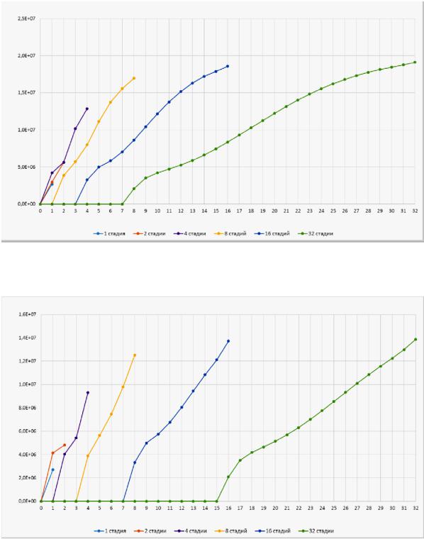
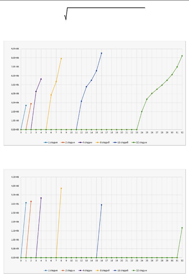
Based on the calculation results, a comparative analysis of the maximum equivalent von Mises stresses in the outer fibers for 1, 8, 16, 24, and 32 rings of the cylindrical shell is performed. The stress variation curves in the shell depending on the number of stages in the calculated case are shown in Fig. 2––6.
Pa
Stage
1 Stage |
|
2 Stages |
|
4 Stages |
|
8 Stages |
|
16 Stages |
|
32 Stages |
Fig. 2. Maximum equivalent von Mises stresses in the outer shells of 01 shell ring
86
Issue № 4 (44), 2019 |
ISSN 2542-0526 |
Pa
Stage
1 Stage |
|
2 Stages |
|
4 Stages |
|
8 Stages |
|
16 Stages |
|
32 Stages |
Fig. 3. Maximum equivalent von Mises stresses in the outer shells of 08 shell ring
Pa
Stage
1 Stage |
|
2 Stages |
|
4 Stages |
|
8 Stages |
|
16 Stages |
|
32 Stages |
Fig. 4. Maximum equivalent von Mises stresses in the outer shells of 16 shell ring
The calculation results show that considering the stages of shell construction in the calculation model causes a significant change in the von Mises stresses in the outer fibers of the cylindrical shell. The von Mises stresses [1, 21] are given by the formula
87
Russian Journal of Building Construction and Architecture
e |
1 |
1 2 2 |
2 |
3 2 3 |
1 |
2 |
, |
(1) |
|
2 |
|
|
|
|
|
|
|
where σ1, σ2, σ3 are the main stresses.
Pa
Stage
1 Stage |
|
2 Stages |
|
4 Stages |
|
8 Stages |
|
16 Stages |
|
32 Stages |
Fig. 5. Maximum equivalent von Mises stresses in the outer shells of 24 shell ring
Pa
Stage
1 Stage |
|
2 Stages |
|
4 Stages |
|
8 Stages |
|
16 Stages |
|
32 Stages |
Fig. 6. Maximum equivalent von Mises stresses in the outer shells of 32 shell ring
88
Issue № 4 (44), 2019 |
ISSN 2542-0526 |
According to the above stress curves, it can be concluded that it will suffice to consider the 8 stages of the shell construction in order to identify the stress-strain of the shell, since at 16 and 32 stages there are no longer any significant changes in the magnitude of internal forces. However, it should be noted that in the first and last ring at 16 and 32 stages of calculation of the stress in the shell continue to vary considerably. This is because when the first shell ring (or the first two, or the first four rings depending on the design case) is activated, a considerable part of the loads from the surrounding base and all the added shell rings are redistributed in the stages that follow. Conversely, in the case of the last ring of the shell, a considerable part of the loads of the surrounding base is already redistributed to the activated rings of the shell, thus a smaller part of the loads accounts for the last ring.
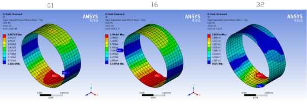
The maximum von Mises stresses occurred in the lower part of the shell and the minimum on the sides. The stress distribution in some rings is shown in Fig. 7 (design case with 32 stages of shell construction).
Fig. 7. Von Mises stress distribution in the outer fibers of some shell rings
2. The calculation model of the shell interacting with the base taking into account changes in the calculation model over time and the coefficient of friction. The following calculation model considers the coefficient of friction f between the shell and the surrounding base. The friction coefficient f is accepted equal to 0.6 as the physical and mechanical properties of the base are accepted for dry soil and those of the shell for concrete [4, 6]. The influence of taking into account the coefficient of friction between the shell and the surrounding base on the internal forces in the shell is identified by means of a comparative analysis between models consisting of 32 design stages with and without taking into account the coefficient of friction f. The von Mises stress variation curves in the outer fibers of the first shell ring of the compared models are provided in Fig. 8.
89