

3649
.pdfRussian Journal of Building Construction and Architecture
BUILDING MECHANICS
DOI10.25987/VSTU.2019.44.4.006
UDC624.21:533.6; 699.83
V. G. Yeremin 1, A. V. Kozlov 2
ANALYTICAL DEPENDENCE OF THE SHIFT FROM THE SHEAR STIFFNESS OF THE SEAM BETWEEN THE CONCRETE SLAB AND STEEL BEAM
IN BRIDGE SPANS
Voronezh State Technical University 1, 2
Russia, Voronezh
1 PhD in Engineering. Assoc. Prof., Head of the Dept. of Highway and Bridge Design, tel.: +7(473)276-83-91 2 Assoc. Prof. of the Dept. of Highway and Bridge Design, tel.: +7(920)402-32-92 e-mail: kozlov.a.v@inbox.ru
Statement of the problem. The current construction regulations of the Russian Federation in the calculation of steel-concrete structures in bridge construction does not take into account the shift at the contact of the steel beam and reinforced concrete slab. The paper aims to assess the effect of shear displacements on the distribution of the stress-strain of the structures under a constant load. Results. Through the course of numerical experiments, it was found that under the assumption of the limit value of slippage between a steel beam and a reinforced concrete slab of steel-reinforced concrete bridge spans, a significant redistribution of stresses between the beam and the slab occurs. Therefore, in the actual design of steel-concrete bridge spans, it is necessary to take into account the shear stiffness between the steel beam and the reinforced concrete slab of the highway.
Conclusions. For a single-span articulated beam with a load uniformly distributed along its entire length, the analytical dependence of the displacement of the reinforced concrete slab on the steel beam as a function of the shear stiffness of the connecting seam is obtained. The lower and upper limits of shearstiffnessdetermininganabsolutelymalleableorabsolutelyrigidconnectionofreinforcedconcrete slabandsteelbeamarecalculated.
Keywords: steel-concrete composite bridges, stress-strain of bridge structures, shear stiffness of the joint.
Introduction. Currently, when calculating steel-reinforced concrete structures in bridge building in accordance with the applicable guideline documents of the Russian Federation (Guideline (СП) 35.13330.2011 “Bridges and Pipes. Updated Version of Design Standards and Norms (СНИП) 2.05.03.84”, Guideline (СП) 159.1325800.2014 “Steel and Concrete
© Yeremin V. G., Kozlov A. V., 2019
70
Issue № 4 (44), 2019 |
ISSN 2542-0526 |
Spans of Road Bridges. Calculation Regulations”) are applied formulas that do not consider a shift in the connecting joint between the reinforced concrete slab and the steel beam.
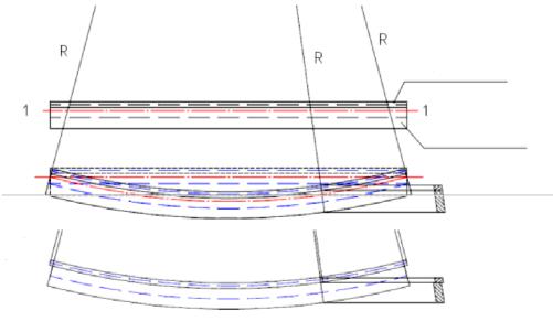
Under the impact of vertical loads for the relative strain diagram, the hypothesis of flat sections is accepted according to which the sections normal to the longitudinal axis of the composite beam (Fig. 1a) remain flat and are not displaced from each other after deformation. Figure 1b shows the deformation scheme of the investigated steel-reinforced concrete beam under the assumption of absolute stiffness of the joint. In this case, the beam is bent with the same radius R which is identical for the reinforced concrete and steel beam measured from the center of bending to the neutral line 1––1 and an arbitrary cross section remains a single hard disk (Fig. 1c). Figure 1d shows the deformation scheme of the same beam under the assumption of complete absence of shear resistance in the connecting joint between reinforced concrete and steel beam. In this case, reinforced concrete bends in its radius Rrc, a metal beam in the radius Rmetal, and the centers of bending of the slab and beam are at different points. As a result, there is a shift of the reinforced concrete slab along the metal beam, equal to zero in the middle of the span and maximum along the edges of the beam. In an arbitrary cross section following a bending deformation in a composite beam, the upper part (concrete) is displaced in relation to the lower part (steel beam) (Fig. 1e). Here: 1––1 is the neutral line of the general steel-reinforced concrete section and the large dashed line separately shows the neutral lines for the slab and the beam.
|
|
|
Rc plate |
a) |
|
|
|
|
|
|
Metal beam (I-beam) |
b) |
|
|
|
|
|
|
c) |
Rrc |
Rmetal |
Rmetal |
Rrc |
|
Rrc |
|
|
d) |
Rmetal |
|
e)
Fig. 1. Deformation schemes of the composite beam
While analyzing the experimental and theoretical studies [12, 18] taking into account the effect of shear between reinforced concrete and steel elements of a composite beam on its
71

Russian Journal of Building Construction and Architecture
stress-strain, significant differences were pointed out in the stiffness values obtained by different authors for the connecting elements of the steel and reinforced concrete parts of the structural cross section. Based on the results of tests of full-scale spans under a temporary load, the authors concluded that the connecting joints have am overall minor effect on the operation of steel-reinforced concrete structures. In the follow-up studies [1, 2, 7, 15, 20], the stress-strain of the investigated structures under constant load significantly was found to significantly depend on shear displacements determined by residual and inelastic as well as creep deformations. Additionally, under a temporary load, the structure operates as elastic one with minor shear displacements and significant shear stiffness of the joint between the plate and the beam. Calculations errors as a result of employing the standard scheme of rigid connection of a reinforced concrete slab and a load-bearing steel beam in bridge construction were noted in [5, 16, 17].
Given all of the deformations, temperature, concrete shrinkage, constant and mobile temporary loads, it is daunting to obtain an analytical solution to the problem. Structural analysis of the structure makes it difficult to choose particular boundary conditions, joining conditions, as well as to assign stiffness characteristics in the area of the joint between the reinforced concrete slab and the steel beam under conditions of forces in different directions. Therefore, even at the early stage, numerical approaches [10] were proposed along with analytical solutions that implement the Wolf method in one of the algorithmic languages of the time. Currently, due to the rapid development of computer technology and related software, numerical solutions of complex technical problems are prevalent in scientific research, in some cases clarifying analytical ones, since they do not make use of hypotheses and assumptions that are accepted in order to obtain final analytical formulas. In the ongoing work, in the numerical study of the work of the steel-reinforced concrete structure under consideration, the LIRA-SAPR licensed software package was utilized to model the construction of road bridges using the finite-element method.
1. Analysis of numerical results. The design scheme modeling the shear stiffness of the connecting elements as well as the results of numerical calculations are presented in [4]. A singlespan beam consisting of a welded I-beam with a solid wall and attached to the upper belt of a reinforced concrete slab with specific material characteristics was considered as a calculation model. The connecting elements (anchors) are modeled in a linear setting, i. e., under the assumption of their elastic shear without achieving the load-bearing capacity and plastic deformations. For the most common structures for combining reinforced concrete slabs with steel
72
Issue № 4 (44), 2019 |
ISSN 2542-0526 |
beams (flexible rod stops), the experimental values of shear stiffness are presented in [11]. But the range of shear stiffness discussed in [4] was expanded so that using the selected finite element model as a pivotally supported single-span beam 24 m long, it would be possible to draw visual graphic dependences of stresses and displacements on these stiffness values. Using numerical experiments, curves were obtained showing the dependence on the linear shear stiffness of the joint: shear at the end of the beam, deflection of the beam, normal tensile stresses in the lower zone of the steel beam, normal compressive stresses in the upper zone of the steel beam and in the reinforced concrete slab.
The Technical Code [13], which is a Russian translation of the Eurocode EN 1994-2: 2006-07, and the guideline [14] define the ductility of a shear joint between concrete and steel elements as follows: “A connecting element can be considered yielding if its characteristic slippage amplitude δuk is not less than 6 mm ”(paragraph 6.6.1.1 [13]). Therefore a rigid (unyielding) joint is one where slip is not over 6 mm. The results of the numerical experiments [4] indicate that assuming a slippage limit value (6 mm) between a steel beam and a reinforced concrete plate of steel-reinforced concrete spans of bridge structures, a significant redistribution of stresses occurs between the beam and the plate: the former is significantly overloaded (especially the upper belt) and receives an additional deflection while the latter, conversely, is unloaded. Moreover, even small values of slippage (up to 1––2 millimeters along the edges of the beam) lead to a significant redistribution of forces between the reinforced concrete slab (the forces decrease in it) and the upper belt of the I-beam steel beam (the forces increase in it). Therefore, in actual design of steel-reinforced concrete bridge spans, it is necessary to take into account the shear stiffness between a steel beam and a reinforced concrete slab of a roadway.
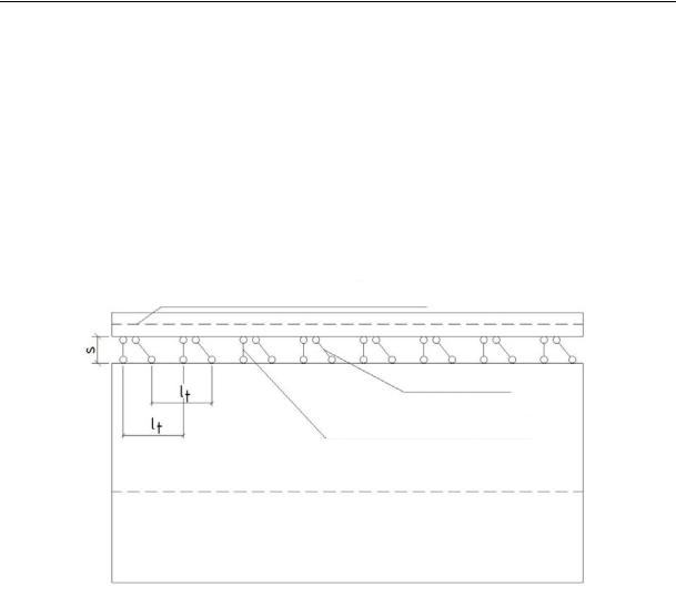
2. Obtaining a functional dependence of shear on the joint stiffness based on numerical experiments. The bonds connecting the reinforced concrete slab and the steel beam can be either continuously distributed along the joint or concentrated at separate points of the rod (discrete). According to their purpose, the bonds in the structure can be divided into 2 types: shear and transverse bonds operating for separation (Fig. 2). When these functions are combined in one connecting element, it is called an anchor and when it only perceives shear forces, it is called a support [3, 9]. The main characteristic of the bonds is determined by the relationship between the strains that occur inside the bonds of the composite beam and the internal forces generated by these strains. In the calculations of steel-reinforced concrete beams, it is recommended that this dependence is assumed to be linear as the load-bearing capacity of anchors and supports is calculated without the assumptions of their plastic operation. Thus,
73
Russian Journal of Building Construction and Architecture
the linear operation of the bonds can be characterized by a stiffness coefficient representing the ratio of the force in the bonds to the corresponding strain:
|
Sh,x k |
, |
(1) |
|
|||
|
x |
|
|
where is the stiffness coefficient for the shear bonds, t/m2 or kN/m2; Sh,x is a shear force per a bond, т or kN; k is the number of bonds per a joint length unit, 1/m; δx is the deformation of the mutual shift of the adjoining fibers of two adjoining rods joined with the shear bonds, m.
Cb – Central line of the RC plate
Shear bonds
Slippage bonds (transverse)
C is the central line of the beam
Fig. 2. Flat calculation scheme of the steel and reinforced concrete beam as a composite structure: s is the conditional joint thickness; lt is a step of discrete bonds along the span axis
Based on the formula (1):
x |
Sh,x k |
. |
(2) |
|
|||
|
|
|
|
Let us look at a hinged beam with a span l loaded with a uniformly distributed load along the entire length q. In an arbitrary section x from the reference section, the transverse force is
Q |
q l |
q x q |
l 2x |
. |
(3) |
2 |
|
||||
|
2 |
|
|
||
For an absolutely stiff shear joint ( ) |
the displacement is |
|||||
in the joint level are given by the Jourawski’s formula: |
|
|
||||
Q Sred |
q(l 2x) Sred |
, |
||||
I |
red |
b |
2 I |
red |
b |
|
|
s |
|
s |
|
||
x 0 and tangential strains
(4)
74
Issue № 4 (44), 2019 |
ISSN 2542-0526 |
where Sred and Ired are the static moment reduced to steel cut off in the joint level of the section and inertia moment of a single steel reinforced concrete section; bs is the joint width that is assumed to equal that of the upper belt of the steel beam (as is the case for most reinforced concrete structures).
During the operation of the composite structure in the shear bonds there are forces that are functions of the coordinate х calculated along the length. These forces attributed to the joint length unit will be denoted as Sx (Sx = Sh,x k, t/m or kN/m). The shear forces Sx impacting the joint length unit for the absolutely stiff bond are as follows:
S |
x |
b |
q(l 2x) Sred . |
(5) |
|
s |
2 Ired |
|
|
|
|
|
|
Inserting (5) into (2), we get the dependence between the displacement and shear stiffness of the joint :
|
x |
|
Sh,x k |
|
f |
q(l 2x) Sred |
. |
(6) |
|
|
|||||||||
|
|
|
|
|
|
2 Ired |
|
|
|
|
|
|
|
|
|
|
|
||
The function f should be identified experimentally and cannot be considered linear in relation to since this expression was obtained assuming that regardless of the value of the influence of the shear stress (4) for a flat section (at ) on the actual shear stress which depends on the stiffness of the joint remains the same.
The shear force Sx as well as the shear δx depend on the shear stiffness of the joint. At 0: Sx = 0, δx in the middle of the span is zero and in the reference section of the beam under a uniformly distributed load, it has a maximum value given by the formula
|
x |
Z |
b,s |
|
16fq |
, |
(7) |
|
|||||||
|
|
|
5l |
|
|||
where Zb,s is the distance between the gravity centers of the concrete and steel sections; |
fq is a |
||||||
stiff bend in the middle of the hinge-supported beam; l is the design span of the beam. |
|
||||||
At 0: δx = 0 (no displacement, the hypothesis on flat sections with no displacement of the composites along the span is met), Sx has a maximum value and is given by the formula (5). The numerical experiments found that regardless of the length of a span, geometric parame-
ters of the components of the rods and uniformly distributed loads for 20000 |
t/m2, the |
||||
dependence x |
f [x, ] for a one-span beam is as follows: |
|
|
|
|
|
x (x, ) 0.36 q (l 2x) Sred |
0.87 . |
(8) |
||
|
|
2 Ired |
|
|
|
75

Russian Journal of Building Construction and Architecture
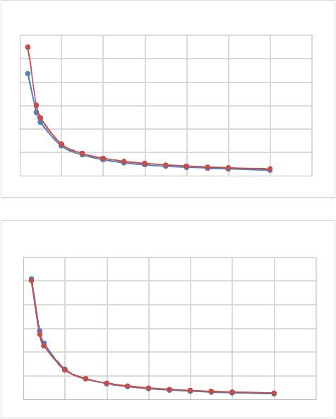
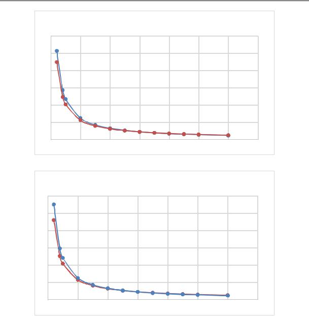
This dependence is confirmed by finite element calculations under different loads (Table 1) for beams of different sections and span lengths (Table 2) selected in accordance with [6, 8, 19]. Figure 3 shows the graphical dependences of shear displacement δx, mm (the ordinate axis) and shear stiffness of the weld, t/m2 (abscissa) obtained using the numerical experiment (blue curves) and analytically using the formula (8) (brown curves) for the arbitrary beam patterns described in Table 1 and 2. It is plain to see from the graphs that starting from the shear stiffness of 20.000 t/m2, experimental and analytical values coincide in the range of the mean square error of no more than 5 %. This is due to the fact that in order to obtain the dependence (8), the criterion of the ultimate shear stress in the flat section (5) was chosen which has an effect at fairly large values of shear stiffness.
|
|
|
|
|
|
|
|
|
|
|
|
|
|
|
Тable 1 |
|
|
Design sections and acting loads |
|
|
|
|
|
|
|
||||||
|
|
|
|
|
|
|
|
|
|
|
|
|
|
|
|
Span length, m |
|
|
|
|
126 |
|
84 |
|
63 |
|
|
42 |
|||
|
|
|
|
|
|
|
|
|
|
|
|
|
|
|
|
Distance х from the support section, m |
|
|
7 |
|
4 |
|
3 |
|
|
2 |
|||||
|
|
|
|
|
|
|
|
|
|
|
|
|
|
|
|
Acting load q, t/m |
|
|
|
|
4 |
|
7 |
|
3 |
|
|
5 |
|||
|
|
|
|
|
|
|
|
|
|
|
|
|
|
|
|
|
|
|
|
|
|
|
|
|
|
|
|
|
|
|
Таble 2 |
Major parameters of steel reinforced concrete beams |
|
|
|
|
|
||||||||||
|
|
|
|
|
|
|
|
|
|
|
|
|
|
|
|
Span length, m |
|
126 |
|
|
84 |
|
63 |
|
|
|
42 |
||||
|
|
|
|
|
|
|
|
|
|
|
|
||||
Sizes |
of the transverse |
sections of the composite elements |
|
|
|
|
|
||||||||
|
|
|
|
|
|
|
|
|
|||||||
Width of the reinforced concrete plate is 3 m, the height is 0.18 m |
|
|
|
|
|||||||||||
|
|
|
|
|
|
|
|
|
|
|
|
|
|
||
Upper belt of the beam, m |
1.05 |
|
0.032 |
1.05 |
|
0.032 |
|
0.75 |
|
0.032 |
0.75 |
|
0.032 |
||
|
|
|
|
|
|
|
|
|
|
|
|
|
|
||
Wall of the beam, m |
0.02 |
|
6.3 |
0.016 |
|
3.6 |
|
0.012 |
|
2.48 |
0.012 |
|
2.48 |
||
|
|
|
|
|
|
|
|
|
|
|
|
|
|
||
Lower belt of the beam, m |
1.05 |
|
0.032 |
1.05 |
|
0.032 |
|
0.75 |
|
0.032 |
0.75 |
|
0.032 |
||
|
|
|
|
|
|
|
|
|
|
|
|
|
|
|
|
Distance from the gravity |
|
|
|
|
|
|
|
|
|
|
|
|
|
|
|
centre of the joined section to |
4.2772 |
2.6735 |
|
2.0287 |
2.0287 |
||||||||||
the bottom of the beamYstb, m |
|
|
|
|
|
|
|
|
|
|
|
|
|
|
|
|
|
|
|
|
|
|
|
|
|
|
|
|
|
|
|
Distance from the gravity |
|
|
|
|
|
|
|
|
|
|
|
|
|
|
|
centre of the reinforced |
|
6.454 |
3.754 |
|
2.634 |
2.634 |
|||||||||
cocnrete plate to the bottom |
|
|
|||||||||||||
|
|
|
|
|
|
|
|
|
|
|
|
|
|
|
|
of the beam, m |
|
|
|
|
|
|
|
|
|
|
|
|
|
|
|
|
|
|
|
|
|
|
|
|
|
|
|
|
|
|
|
Static moment of the part |
|
|
|
|
|
|
|
|
|
|
|
|
|
|
|
of the section cut off the joint |
0.2116 |
0.105 |
|
0.0588 |
0.0588 |
||||||||||
level Sred, m3 |
|
|
|
|
|
|
|
|
|
|
|
|
|
|
|
Inertia moment of the steel |
|
|
|
|
|
|
|
|
|
|
|
|
|
|
|
reinforced concrete section |
1.7827 |
0.4857 |
|
0.1711 |
0.1711 |
||||||||||
Ired, m4 |
|
|
|
|
|
|
|
|
|
|
|
|
|
|
|
76
Issue № 4 (44), 2019 |
ISSN 2542-0526 |
In the ranges of to 20.000 t/m2, if necessary, the criterion of maximum theoretical shift in the support zone for unified structural elements should be used (at 0). The joint stiffness20000 t/m2 should be assumed to be the same as the boundary value between the elastically yielding and absolutely yielding joint. For the elastically yielding joint, the calculation of the VAT of a steel-reinforced concrete beam should be performed considering the slippage δx obtained according to (8) as for the composite structure with shear bonds. For 20.000 t/m2 the calculation should be carried out just in case as for the composite structure of two different elements with no shear bonds regardless of the span and acting loads.
42 m
63 m
Fig. 3. Comparison of the numerical (blue curve) and analytical (brown curve) dependencies for the beams of different spans
77
Russian Journal of Building Construction and Architecture
84 m
126 m
Fig. 3 (end). Comparison of the numerical (blue curve) and analytical (brown curve) dependencies for the beams of different spans
3. Identifying the upper limit of the shear stiffness ς when the calculation is permitted without taking into account the relative shear. The longitudinal force N in each part of the composite steel-reinforced concrete beam varies from 0 at the beginning of the beam to S in the arbitrary section x from the beginning of the beam where S is the total shear force in the joint accumulated along the length of the structure from the beginning to the section in question and given by the equality
S x |
Sx dx. |
(9) |
0 |
|
|
78
Issue № 4 (44), 2019 |
ISSN 2542-0526 |
The linear shear force is identified above as the product of the shear force in one anchor by the number k of anchors per unit length: Sx = Sh,x k. Considering the formula (1) using (9) we get:
N |
S x Sx dx x x dx. |
(10) |
00
I.e., the linear shear force Sx is the product of the shear stiffness of a unit of joint length and the amount of shear in this length unit (which is only the case for calculations in a linear setting). There is some uncertainty caused by (10) which is limited by the logically limiting shear force
calculated based on the hypothesis of flat sections without shear: at x 0 and the indefinite product of infinity by zero ( x ) for a hinge-supported beam with uniformly distributed load q should be equal to the shift according to the Jourawski’s formula for flat sections according to the formula (5). Denoting in the relation (8) obtained above, m = 0.36, n = 0.87 and substituting the expression for x in the formula (10), we get:
|
x |
|
q(l 2x) Sred |
|
n |
|
|
|
|
|
|||||
|
|
|
|
||||
N |
m |
|
dx, |
(11) |
|||
2 Ired |
|||||||
|
0 |
|
|
|
|
||
where the transverse force N in any section is limited by the specific value calculated using the classic approach assuming there is no shear:
N |
x |
q(l 2x) Sred dx. |
(12) |
|
0 |
2 Ired |
|
Let us solve the integral equation (11) for the hinge-supported single-span beam of a constant cross section loaded along the entire length with a uniformly distributed load q. We represent the equality (11) as follows
|
x |
|
Sred |
|
n |
|
|
|
|||||
|
|
|
||||
N |
1 n m |
q |
|
(l 2x)n dx. |
||
|
|
|||||
|
0 |
2 Ired |
|
|||
Assuming there are shear bonds with which is constant along the length we can assume
|
|
|
|
n |
const. |
|
|||
|
1 n m q |
Sred |
|
||||||
|
|
2 Ired |
|
|
|
|
|
||
Ultimately we get |
|
|
|
|
|
|
|
|
|
|
x |
|
|
|
|
|
n 1 |
(l 2x) |
n 1 |
N |
(l 2x) |
n |
dx |
l |
|
|
|||
|
2 |
|
|
n 1 |
. |
||||
|
0 |
|
|
|
|
|
|
||
(13)
(14)
In the formula (14) at fairly large shear stiffness values (over 1500 МН/m2), the longitudinal force exceeds the limit value calculated using the classical approach assuming there is no
79