

3490
.pdfIssue № 2(34), 2017 |
ISSN 2542-0526 |
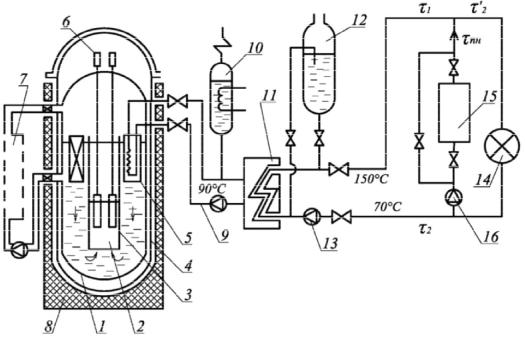
The first contour (Fig. 3) consists of a reactor 1 with four parallel loops (in Fig. there is one loop), each of which includes a steam generator 9, the main circulating pump (MCP) 10, the main isolation valves 8 main circulation pipelines where the organization of several parallel loops makes redundancy of equipment in particular of circulation pumps unnecessary. The water in the reactor is supplied at the pressure of 16.6 MPa with the temperature of 562 K. In the core it is heated up to 595 and is sent to the steam generator where it is cooled giving heat to the secondary coolant. The boiler water enters the main circulation pump which returns it to the reactor. Between the reactor and steam generator there are the main isolation valves that can shut off any loop from the reactor. MCP is installed on the disconnected part of the "cool" pipeline. To create the required pressure for a steam compensator (SC) 6, the steam condensator is used. It also serves to compensate for volume changes of the coolant by heating it at the circuit and the initial pressure. Water in is heated by the heaters 7 and partially vaporized resulting in the necessary pressure. SC is connected to a hot pipe on the side that is kept switched on.
Fig. 3. Scheme of the first circuit of NPP with the reactor VVER-1000:
1 is a reactor; 2 is an accumulator; 3 is a bubbler; 4,5 are safety valves; 6 is a pressure compensator; 7 is a heater; 8 are the main isolation valves; 9 is a steam generator; 10 is a reactor coolant pump; 11 is a heat exchanger; 12 is a refrigerator; 13 is a filter; 14, 16, 18 are pumps; 15, 17 are tanks with boric acid solution
21

Russian journal of building construction and architecture
To prevent the pressure SC from exceeding the allowable into the steam space, heat is injected from the cool part of the pipeline. If the injection of the cool keeps resulting in an increase in the pressure, safety valve 5 opens, the output of which is connected to a bubble counter 3. The water temperature in the bubbler is maintained at ~333 K for condensing steam from SC. If the bubbler pressure increases above acceptable, the safety valve 4 in the bubbler will switch on and the heat carrier will be emitted from the first circuit.
The water of the first circuit when the reactor obtains a highly induced radioactivity, as there are always impurities that are activated in the active area. As a result, the first circuit equipment becomes a source of ionizing radiation and thus is placed in unattended areas. To clean the heat carrier off impurities a part of it (a so-called purging) with the flow rate of 22 kg/s with the pressure side coolant is diverted into the filter 13. Before entering the filters, the purge water is cooled down to 318 K. Cooling occurs due to the heating of the purified water in the regenerative heat exchanger 11, after which the filter returns to the loop in the suction branch of the MCP. The final cooling of the purge water is performed using technical water in the fridge 12. Compensation for the losses of the first coolant and the first filling of the circuit produces a charging pump 14 of the special system of the preparation of pure capacitors. Nuclear facilities are equipped with systems of emergency cooling of the active zone of the reactor (ECCS) that provide heat removal from the reactor in case of accidents with the loss of the first coolant. In emergency situations, when the loss of coolant occurs at a slow speed, high pressure pumps are included. At significant depressurization, up to the full instantaneous rupture of a circulation pipe, at first the water is supplied from the accumulator, then high pressure pumps are included, and, if their supply is not enough to maintain the pressure in the circuit a low-pressure pump starts operating.
2. Schematic diagram of the nuclear stations of heat supply. The most cost-efficient use of nuclear fuel is achieved when applied to nuclear power plants. However, in some cases the use of nuclear stations of a heat supply is economically justified. The purpose of the ACT is the production of heat for household and business needs.
The feasibility of the construction of the AST is determined by the following factors:
1)significant facilitation of the conditions for the selection of construction sites for ACT that do not require water resources and additional investments for the construction of systems of technical water supply;
2)great radiation safety of AST compared to the ACEP that allows it to be located at a inconsiderable distance from the consumer;
22
Issue № 2(34), 2017 |
ISSN 2542-0526 |
3)vicinity of AST allows one to avoid significant heat losses during transportation of a heat carrier, to reduce the costs for pumping of a coolant (design of the study the ATEC shows that the costs of transit heat networks is approximately 15 % of the that of the plant);
4)a relatively small value of the required area, less environmental pollution by harmful emissions at the normal and emergency modes of operation.
One of the possible methods of increasing the effectiveness of the AST is to increase the coefficient of the use of its installed capacity that can be achieved by the co-joint operation of AST and peak water-heating boiler stations which provide a covering of the graph of peak thermal load. Providing this part of the graph of the heat load with a peak of sources allows one to increase the duration of the operation of AST at its rated power and to reduce the influence of daily fluctuations of load of hot water supply for its operation mode. The efficiency and reliability of the AST depends on the choice of rational modes of its operation along with peak boilers that must generally be located in the center of thermal loads. In this case, there are two possible schemes of the connection of AST and a peak boiler: the serial and the parallel one. A thermal scheme of the ACT with parallel of a peak boiler is shown in Fig. 4.
Fig. 4. Scheme of a nuclear power station heating:
1 is a reactor vessel; 2 is a core; 3 is a mine of the contour of a natural circulation; 4 is a safety body; 5 is heat exchanger of the second circuit; 6 is the shutoffs of the control system control and reactor protection; 7 are extra systems of the first circuit; 8 is a ferroconcrete shaft; 9 is the second circuit; 10 is a volume compensator; 11 is network heat exchanger; 12 is a system of emergency cooling; 13 is a pump; 14 is a heat consumer;
15 is a peak boiler; 16 are the pumps of the peak boiler
23

Russian journal of building construction and architecture
For the ACT a corpus of pressurized water reactor as more reliable compared to the channel water-graphite reactor. The relatively low pressure inside the reactor leads to a significantly smaller load on the wall and roof of the body of the reactor. To improve the reliability there is a so-called safety case, the main purpose of which is the prevention of coolant leakage of the heat carrier in case of depressurization of the body of the reactor. The concrete shaft is mainly designed to protect against radiation, but it allows one to take additional measures to prevent leaks of the first heat carrier into soil. The heat carrier of the third circuit circulates in the central heating system of residential and public buildings after mixing with water coming from a peak boiler connected with the AST.
Conclusions
1.The thermal schemes of nuclear power plants of heat supply and atomic heat and power plants as well as the parameters of the basic units examined in the article can be used as a source for searching the most optimal modes of operation to allow one to determine the ways of improving the basic circuits of nuclear power plants as a result of more in-depth analysis.
2.An increase in the cost efficiency of nuclear stations of heat supply is possible when they operate jointly with peak boilers located in the centre of thermal loads. At the same time it should be noted that the vicinity of the stations from the city determines higher requirements for the reliability of the station.
References
1.Ignatov V. I. e. a. Heatand Neutron-Physical Characteristics of Power-Generating Units of Nuclear Power Plants with Vver-1000 during Operation Above Nominal Power: (for the Example of the No. 2 Unit of the Balakovo Nuclear Power Plant). Atomic Energy, 2009, no. 1 (107), pp. 9—17.
2.Gorlinskii Yu. E. e. a. Securing the Radiological Safety of People and the Environment at All Stages of the Life Cycle of Float-ing Nuclear Heat-and-Power Plants. Atomic Energy, 2009, no. 2 (107), pp. 122—129.
3.Aminov R. Z., Beresh V. T. Safety Assessment of a Nuclear Power Plant with Gas-Turbine Back-up for Internal Needs. Atomic Energy, 2004, no. 6 (96), pp. 434—438.
4.Sokolov A. S. Numerical Simulation of the Thermal Conditions in a Sea Bay Water Area Used for Ater Supply to Nuclear Power Plants. Power Technology and Engineering, 2013, no. 2 (47), pp. 139—142.
5.Gagarinski A. Bilibino Heat and Power for Russia’S Northern Regions. Nuclear Engi-neering International, 1995, no. 40, pp. 14—15.
6.McDonald C. F. Mobile Hybrid (Nuclear/Oil Fired) Gas Turbine Cogeneration Power Plant Concept. Applied Thermal Engineering, 1998, no. 6 (18), pp. 353—368.
24
Issue № 2(34), 2017 |
ISSN 2542-0526 |
7.Mel'kumov V. N., Kuznetsov I. S., Kobelev V. N. Zadacha poiska optimal'noy struktury teplovykh setey [The task of finding the optimal structure of heat networks]. Nauchnyy vestnik Voronezhskogo GASU. Stroitel'stvo i arkhitektura, 2011, no. 2, pp. 37—42.
8.Medvedevа O. N. The Selection of Gas Pipeline Route on the Plan of Gas Supplied Area. Scientific Herald of the Voronezh State University of Architecture and Civil Engineering. Con-struction and Architecture, 2011, no. 3, pp. 26—35.
9.Mel'kumov V. N., Chuykin S. V., Papshitskiy A. M., Sklyarov K. A. Modelirovanie struktury inzhenernykh setey pri territorial'nom planirovanii goroda [Modeling of the structure of utility networks the regional planning city]. Nauchnyy vestnik Voronezhskogo GASU. Stroitel'stvo i arkhitektura, 2015, no. 2 (38), pp. 41—48.
10.Miram O. Teplosnabzhenie ot atomnykh istochnikov [Heat supply from nuclear sources]. Santekhnika, otoplenie, konditsionirovanie, 2010, no. 7 (103), pp. 48—49.
11.Puzakov V. S. Teplosnabzhenie ot AES v Evrope [Heat supply from nuclear power in Europe].
Santekhnika, otoplenie, konditsionirovanie, 2013, no. 3 (135), pp. 60—63.
12.Bocharov V. L., Smirnova A. Ya., Bugreeva M. N. Vliyanie atomnykh teplo- i elektrostantsiy na geologicheskuyu sredu (Tsentral'no-chernozemnyy ekonomicheskiy rayon) [The effect of atomic heat and power plants in the geological environment (the Central black earth economic region)]. Vestnik Voronezhskogo gosudarstvennogo universiteta. Geologiya, 1996, no. 1, pp. 165—171.
13.Mel'kumov V. N., Kuznetsov C. N., Sklyarov K. A., Gorskikh A. A. Monitoring nadezhnosti teplovykh setey [Monitoring the reliability of thermal networks]. Nauchnyy vestnik Voronezhskogo GASU. Stroitel'stvo i arkhitektura, 2010, no. 1, pp. 52—58.
14.Muramovich V. G., Petukhov V. V., Skorokhodov D. A. Al'ternativa plavuchim atomnym teploelektrostantsiyam [The alternative of floating nuclear power plants]. Al'ternativnaya energetika i ekologiya, 2014, no. 18 (158), pp. 65—69.
15.Grimes R. W., Nuttall W. J. Generating the Option of a Two-Stage Nuclear Renaissance. Science, 2010, no. 329, pp. 799—803.
16.Mel'kumov V. N., Kuznetsov I. S., Kobelev V. N. Vybor matematicheskoy modeli trass teplovykh setey [The choice of the mathematical model tracks thermal networks]. Nauchnyy vestnik Voronezhskogo GASU. Stroitel'stvo i arkhitektura, 2011, no. 2, pp. 31—36.
17. Seredin P. V., Glotov A. V., Ternovaya V. E. e. a. Spinodal decomposition of Ga (x) In1-x As (y) P1-y quaternary alloys. Semiconductors, 2011, vol. 45, iss. 11, pp. 1433––1440.
25

Russian journal of building construction and architecture
DESIGNING AND CONSTRUCTION OF ROADS,SUBWAYS,
AIRFIELDS,BRIDGES AND TRANSPORT TUNNELS
UDC 625.7/.8
B. A. Bondarev1, L. A. Prozorova2, Yu. V. Shtephan3
STONE MATRIX ASPHALT BASED ON A CUBE-SHAPED SLAG RUBBLE
Lipetsk State Technical University
Russia, Lipetsk, tel.: +7(474)2-328-083, e-mail: ialex-86@mail.ru, www.stu.lipetsk.ru, 1D. Sc. in Engineering, Prof. of the Dept. of Building Materials
Bellelli Emirates Engineering General Contracting LLC Project
Abu Dhabi –– UAE, Airport Road –– SJ Tower, Suite 10, tel.: +971.244.55830, e-mail: lyudmila_prozoro@mail.ru, www.bellellieng.com
2Manager PhD
Automobile and Road Construction State Technical University (MADI), Russia, Moscow, tel.: +7(499)155-03-30, e-mail: shtephan@madi.ru, www.madi.ru
3Assoc. Prof., Dept. of Production and Maintenance of Automobile and Road Building Machines, PhD
Statement of the problem. This work considers stone matrix asphalt based on cube form blastfurnace cast slag rubble manufactured using modern cone crushers, investigates their properties and compositions and determines pavement durability.
Results. The properties of blast-furnace slag rubble tests are shown as wellas the results of tests of asphalt compositions based on this rubble properties. The outcomes of major maintenance of stone matrix asphalt based on blast-furnace slag implementation in the streets of Lipetsk are presented. This asphalt compositionhasincreasedpavementbearingcapacity.Thedurabilityofthispavementwasinvestigated. Conclusions. Domestic and foreign cube-shaped rubble optimal shape delivering practice allows one to produce rubble on modern secondary and tertiary crushing machines by crushing-separating equipment operation optimization. The optimal rubble is the one with lamellar and needle particles content lower than 10 %. It is experimentally determined that the first group rubble production is considered not effective. It is shown that blast-furnace slag rubble usage at SMA production allows one to deliver a high-quality pavement top layer with no less than 10 years’ life cycle.
Keywords: cast slag rubble, asphalt based on slag, cone crusher, screening, fractions, cube form, rutting.
Introduction
Traffic speeds and loads on pavements have increased over the recent years. Therefore it has become essential to increase the bearing capacity of pavements.
© Bondarev B. A., Prozorova L. A., Shtephan Yu. V., 2017
26
Issue № 2(34), 2017 |
ISSN 2542-0526 |
It requires the use of more durable and reliable deformation and rutting resistant road building materials. These materials have to be resistant to moisture and abrasion.
Previous maintenance of urban roads and highways in Lipetsk and the region showed that asphalt based on substrate of cube cast slag rubble has such properties. This rubble is delivered with the use of layered drain and slow cooling for crystallization of blast-furnace cast slag with the basicity module less or equal to 1. Rubble is made cube-shaped by means of modern import crushers of Sandvik RC 3800 type. It provides 5––15 mm grains mostly cube-shaped ones and the minimal content of lamellar and needle grains because GOST 8267-93 makes increased demands on these types of grain content within rubble. Modern Hydrocone cone crushers made by Swedish brand Sandvik meet these requirements.
This equipment feature is eccentricity change ability for rubble quality regulation depending on the properties of base rock. Sandvik Roadclassfier RC-3800 crusher is set to operate with granite rubble at dumping slot of 12 mm. It allowed one to obtain the second-group rubble by lamellar grains in a mix of 5––10 mm and 10––15 mm fractions with a 15––40 mm fraction at input.
There are advantages of blast-furnace cast slug rubble:
––Increase in plastic deformations and rutting durability. It is proved by foreign researchers also [1, 4––7];
––Increased rubble grains surface porosity that allows bitumen to stream in pores and improves adhesion;
––Acid blast-furnace slag resistance to all types of self-decay (silicate, calcareous, ferrous);
––Lack of rubble grains polishing that allows one to form micro roughness of pavement and improve friction between tire and surface on wet road.
There are disadvantages of blast-furnace cast slug rubble:
––Decreased strength and abrasion compared to granite rubble although compressive strength at pressing at a cylinder could reach 900––100 grade depending on crystallization level;
––Dust particles formation during rubble less than 20 mm production;
––Demand of bitumen binder consumption increase for steady high porosity substrate grains coating [6].
As it was previously showed [2], these disadvantages could be decreased by adding modifiers in an asphalt mix and by attaching a cube shape to rubble grains. In the present work we set out to optimize based on cube slag substrate asphalt composition, to determine its physical mechanical properties and to predict the durability of SMA pavement.
27

Russian journal of building construction and architecture
Earlier we showed blast-furnace slag usage in SMA composition expediency. For producing cube form rubble there is screening dust loaded to input from previous crushing stage (of jaw crusher) with a maximum particle size of less than 70 mm. A stone of more than 15mm fraction falls in operational crushing chamber to provide maximal secondary crushing facility performance. A fraction of less than 15 mm is loaded at once on a conveyer to separator passing crushing chamber. Wherein only +15 mm fraction falls in operational chamber. Therefore a disadvantage of this crusher is that there might be lamellar and flakiness particles with size of 5––15 mm left on the input from previous crushing stages to vendible fractions.
When bitumen and cube slag materials come in contact, the physical and chemical sorption bonds strongly hold bitumen membrane on the surface of a mineral aggregate. Slag surface porosity leads to binder and its components filtration into rubble grains when mixed with bitumen. Wherein oils penetrate grains to the maximal depth. Less fluid pitches penetrate to less depth. Therefore bitumen surface layer on slag grains is enriched with an asphalt that increases the surface strength, heat and wear resistance of SMA. Due to bitumen components and selective filtration there is formation of stiffer and less elastic bitumen membranes on slag aggregate that increase the SMA density [3]. Physical, chemical, electrostatic and diffusional processes occur. As a result, adhesive bonds on bitumen –– aggregate border become more durable and resistant to an environmental influence at the mixing moment and during further time. Blast-furnace slag rubble could be used for SMA-10, 15 and 20 hot production. Slag sands and granulated slags are not recommended for asphalt production due to their low strength. However, large and small same chemical and mineral structure aggregate usage contributes to denser and monolith conglomerate if quartz sand that has the above disadvantages is used [3].
As can be seen, it is clear that there are unsolved problems of optimal compositions delivering and asphalt based on slag cube rubble durability prediction. This shape of the grains allows one not only to decrease expensive bitumen binder consumption but also to reduce pavement rutting and increase its strength and wear resistance as well as proved in [5––7].
Slag rubble cube form industrial production
At first the properties of blast-furnace cast slag aggregate were investigated. It is determined that granulometric composition of cube-shaped rubble delivered on Hydrocone industrial cone crusher made by Swedish brand Sandvik meets GOSTs requirements on lamellar form grains and could be used in the SMA composition.
28

Issue № 2(34), 2017 |
ISSN 2542-0526 |
The physical and mechanical properties of the resulting rubble compared to those of granite rubble were determined. The results are shoen in Table 1 that shows that blast-furnace slag rubble has no worse properties than does granite rubble.
|
|
|
Table 1 |
Blast-furnace slag and granite rubble properties |
|
|
|
|
|
|
Granite rubble |
Properties |
Slag rubble |
||
|
|
|
|
Fraction size, mm |
10––20 |
|
10––20 |
|
|
|
|
Strength mark |
1000 |
|
1000 |
|
|
|
|
Abrasiveness mark |
A II |
|
A II |
|
|
|
|
Frost-resistance mark |
150 |
|
150 |
|
|
|
|
Density, g/cm |
2.80 |
|
2.5––2.9 |
|
|
|
|
Water absorption, % of mass |
5.1 |
|
0.1––1 |
|
|
|
|
Practical studies showed that two crushing stages in that type of crusher are not enough for the production of cube-shaped slag rubble. Interim stage for providing operation under block on crushing third stage is necessary to allow the production of a 15––40 mm fraction. Wherein flakiness particles of less than 10––12 % content at all of slag and cube rubble vendible fractions. Therefore it is justified and approved that there is a possibility to obtain blastfurnace cast slag rubble of the average II class using flakiness grains content. Grain form improvement is possible by interim crushing as well.
Slag rubble based on designing SMA pavement
The experiment was planned in order to optimize the SMA composition not by substrate expense only but also using a modifier and bitumen binder. In a mineral mix composition whose components ratio was determined by means of the maximum aggregate density, there was 65 % of less than 5 mm sand fraction and 35 % of 5…10 (5––15) mm fraction slag rubble, other materials were added over 100 % of a mineral mix. In order to optimize the SMA composition the experiment was performed and planned as a three-factor orthogonal central composition (OCCP). Wherein there are the following SMA-15 regression equations:
for compressive strength at 20°С response, MPa:
у1 = 3.72 + 0.117х1 + 0.079х2 + 0.028х3 – 0.073х1х2 + 0.057х2х3 + 0.234х12 – 0.091х22, (1)
for compressive strength at 50°С response, MPa:
у2 = 0.724 + 0.017х2 + 0.01х3 + 0.01х2х3 – 0.012х12 – 0.019х22, |
(2) |
29

Russian journal of building construction and architecture
for crack resistance:
у5 = 3.512 – 0.155х1 + 0.1х2 – 0.209х3 + 0.034х1х2 – 0.041х1х3 – 0.008х12 + 0.029х22. (3)
These formulas allow one to predict blast-furnace slag based SMA properties depending on the composition. The optimal SMA composition was implemented in 2012 during major maintenance of highways in Lipetsk. For this purpose pavement with the investigated composition based top layer development was implemented. “Civil Project of Lipetsk” Plc, developed pavement construction scheme construction scheme includes: stone matrix asphalt SMA-15 –– 4 cm; B type dense coarse-graded hot mix asphalt based –– 6 cm; II mark asphalt treated permeable bases –– 8 cm; bound black chippings –– 10 cm; bound graded rubble made of dense rock –– 15 cm; sand (GOST 8736) –– 30 cm; soil (heavy loam). Layers thickness calculations allowed one to reduce the thickness of the top layer from 5 to 4 cm without decreasing its bearing capacity by means of the SMA increased density and strength. For SMA deformability assessment elastic modulus calculations were performed. The construction meets the requirements for the durability and reliability by the elastic modulus value given that:
Etl ≥ ЕminKnel, |
(4) |
where Еtl and Emin are the estimated total and minimal required elastic modulus of apavement, MPa; Кnel is a strength safety factor by means of the elastic modulus criteria, for the reliability level 0.98 Кnel = 1.
The necessary total elastic modulus was calculated by means of the following formula:
Emin = 98.65 [lg∑Np – c], MPa, |
(5) |
where ∑Np is a total of an estimated load applications number for a pavement life cycle; с is an empirical parameter for the estimated axis load of 100 kN which is с = 3.55. By means of Formula 5, the estimated elastic modulus was obtained:
Emin = 98.65 [lg∑Np – c] = 98.65 (lg1022958 – 3.55) = 242 MPa.
The elastic modulus of pavement layers was identified when calculating using the allowable elastic deflection at 20 °С and when calculating monolith layers for bending at 10 °С. A structure based on a granite rubble with 4 cm of SMA-15 top layer meets the requirement for strength using the allowable elastic deflection. The strength safety factor is Кnel = 1.06.
It is shown in the course of the calculations that SMA based on slag aggregate has a higher load capacity compared to SMA based on granite rubble when the thickness decreases from
30