

3456
.pdfIssue № 4(32), 2016 |
ISSN 2075-0811 |
Based on the results of the computational experiment, i.e. mathematical modelling of flowing of a heat-exchange surface of a shell-and-tube heat exchanger with a fluid, the following conclusions can be made:
1.As the speed of a fluid flow increases, so does the flow turbulization behind a cylindrical rib (in the direction to the fluid flow);
2.Up to the fluid speed of 0,7 m/seс in a high-turbulent area there is mainly the front part of a cylindrical rib (in the direction to the fluid flow), less of a flat surface of a plate (Fig. 4a, 4b) starting with the speed of 0,7 m/seс, the fluid flow with high turbulization captures the surface of a palte as well (Fig. 4c, 4d), i.e. turbulization increases;
3.A significant increase in the turbulization takes place starting with the speed of 0,7 m/seс (Fig. 4c). At smaller fluid speeds (0,1—0,4 m/seс) at the distance of less than 10 N from the rib, turbulization strives for 0 (Fig. 4b, 4c);
4.Most of a heat-exchange surface (a plate as well as the front of a rib) is in high turbulization at the flow speed of 1 m/seс (Fig. 4d), at this speed the distance from the centre of the ribs till intensity drops is roughly 9 N (36 mm).
Conclusions
1.Therefore the selected passive method of intensifying heat exchange by changing the geometry of a heat-exchange surface by adding cylindrical ribs promotes turbulization of a fluid flow.
2.It was experimentally found that at the distance between ribs of 8,3 N (36 mm) turbulization at the front of the next rib is still significant. This allows a step between ribs to be increased with the hydraulic resistance remaining relatively low.
3.High turbulization will cause the heat transfer coefficient of a shell-and-tube heat exchanger to increase ultimately resulting in a decrease in the sizes of a heat exchanger and its steel intensity.
4.As a result of a number of theoretical and experimental studies, a construction of a highly effective shell-and-tube heat exchanger was proposed [14, 15] based on the passive method of increasing intensity of heat exchange. In this heat exchanger the geometry of heat-exchange surfaces is changed and extra cylindrical ribs are added.
References
1. Anisin A. A., Anisin A. K., Buglaev V. T. Turbuliziruyushchee vliyanie gladkikh krugovykh tsilindricheskikh elementov na intensifikatsiyu teploobmena simmetrichnogo koridornogo puchka trub [Turbulators effect of smooth circular cylindrical elements on the intensification of heat transfer symmetric corridor tube bundle]. Izvestiya vuzov. Yadernaya energetika, 2000, no. 1, pp. 64—76.
31

Scientific Herald of the Voronezh State University of Architecture and Civil Engineering. Construction and Architecture
2.Anisin A. A. [Improving the heating efficiency of the cross-streamlined bundles of smooth tubes with complex geometry surface]. XIV Minskiy mezhdunar. forum po teplo- i massoobmenu: tezisy dokladov i soobshcheniy, 10—13 sentyabrya 2012 g. [XIV Minsk International Heat and Mass Transfer Forum: Abstracts of the Reports and Communication]. Minsk, Institut teplo- i massoobmena NAN Belarusi, 2012, vol. 1, part 2, pp. 29—33.
3.Bazhan P. I., Kanevets G. E., Seliverstov V. M. Spravochnik po teploobmennym apparatam [Handbook for heat exchangers]. Moscow, 1989, 200 p.
4.Buglaev V. T., Anisin A. A. Intensifikatsiya teploobmena pri poperechnom obtekanii koridornogo puchka trub s turbuliziruyushchimi potok sterzhnyami [Intensification of heat transfer during crossflow corridor of the bundle of tubes with turbulators of the flow rods]. Teploenergetika, 2002, no. 3, pp. 23—27.
5.Voronin S. V., Yushin V. D., Bunova G. Z. Fizicheskie svoystva metallov: konspekt lektsiy. Ch. 1 [Physical properties of metals: lectures. Part 1]. Samara, 2012.
6.Evenko V. I., Anisin A. K. Issledovanie lokal'nykh teplogidravlicheskikh kharakteristik vertikal'nykh puchkov trub pri izmenenii orientatsii ikh elementov [Study of local thermal-hydraulic characteristics of vertical tube bundles when you change the orientation of their elements]. Teploenergetika, 1991, no. 5, pp. 51—56.
7.Zhukauskas A. A. Konvektivnyy perenos v teploobmennikakh [Convective transfer in heat exchangers]. Moscow, Nauka, 1982. 472 p.
8.Kaplun A. B., Morozov E. M., Olfer'eva M. A. ANSYS v rukakh inzhenera. Prakticheskoe rukovodstvo
[ANSYS in the hands of the engineer. A practical guide]. Moscow, Editorial URSS, 2013. 272 p.
9.Kutatelladze S. S. Osnovy teorii teploobmena [Fundamentals of the theory of heat transfer]. Moscow, Atomizdat, 1973. 416 p.
10.Kutatelladze S. S. Teploperedacha i gidrodinamicheskoe soprotivlenie: spravochnoe posobie [Heat transfer and hydrodynamic resistance: reference manual]. Moscow, Energoatomizdat, 1990. 368 p.
11.Kushchev L. A., Nikulin N. Yu., Ryapolov A. N. [Modern methods of increasing the efficiency of heating systems]. Trudy Vserossiyskoy nauchno-prakticheskoy konferentsii «Povyshenie effektivnosti stroitel'nogo proizvodstva za schet primeneniya novykh materialov i innovatsionnykh tekhnologiy» [Proceedings of Russian scientific-practical conference "Improving the efficiency of the construction production through the use of new materials and innovative technologies"]. Ryazan, 2013, pp. 113—118.
12.Mikheev M. A., Mikheeva I. M. Osnovy teploperedachi [Fundamentals of heat transfer]. Moscow, Energiya, 1977. 344 p.
13.Nashchokin V. V. Tekhnicheskaya termodinamika i teploperedacha [Technical thermodynamics and heat transfer]. Moscow, Vysshaya shkola. 497 p.
14.Nikulin N. Yu., Kushchev L. A., Suslov D. Yu., Uvarov V. A., Feoktistov A. Yu. Kozhukhotrubyy teploobmennyy apparat [Countryby heat exchanger]. Patent RF, no. 2014134083/06, 2015.
15.Kushchev L. A., Nikulin N. Yu., Uvarov V. A. Skorostnoy teploobmennyy apparat [High-speed heat exchanger]. Patent RF, no. 2015110302/06, 2015.
16.Sivukhin D. V. Obshchiy kurs fiziki. T. II. Termodinamika i molekulyarnaya fizika. [The course of General physics. Vol. II. Thermodynamics and molecular physics]. Moscow, Fizmatlit, 2005. 544 p.; T. III. Elektrichestvo [Vol. III. Electricity], 2004. 656 p.
17.Sokolov E. Ya. Teplofikatsiya i teplovye seti [District heating and heat networks]. Moscow, Energoizdat, 1982. 360 p.
32
Issue № 4(32), 2016 |
ISSN 2075-0811 |
18.Bergles A. E. [Techniques to Augment Heat Transfer]. Handbook of Heat Transfer. N.-Y., McGray-Hill, 1973, pp. 10.1—10.3.
19.Lunsford K. M. Increasing Heat Exchanger Performance. Bryan, Texas, Bryan Research & Engineering Inc., 2006. 13 p.
20.Kline S. J., Reynolds W. C., Schraub F. A., Runstadler P. W. The Structure of Turbulent Boundary Layers.
J. Fluid Mech, 1967, vol. 30, pp. 741—773.
21.Menter F. R. Two-Equation Eddy-Viscosity Turbulence Models for Engineering Applications. AIAA Journal, 1994, vol. 32, no. 8, pp. 1598—1605.
22.Seredin P. V., Goloshchapov D. L., Kashkarov V. M., Ippolitov Y. A., Prutskij T. Emission properties of biomimetic composites for dentistry. Results in Physics, 2016, vol. 6, pp. 447––448. doi: 10.1016/j.rinp.2016.08.003.
33

Scientific Herald of the Voronezh State University of Architecture and Civil Engineering. Construction and Architecture
UDC 621.642.86
O. N. Medvedevа1, V. O. Frolov2, A. I. Kolosov3
THEORETICAL SUBSTANTIATION OF METHOD OF DELIVERY
LIQUEFIED NATURAL GAS
Yuri Gagarin State Technical University of Saratov
Russia, Saratov, tel.: (8452) 99-88-93, e-mail: medvedeva-on@mail.ru
1D. Sc. in Engineering, Assoc. Prof. of Dept. of Heat and Gas Supply, Ventilation,
Water Supply and Applied Hydro and Gas Dynamics
2PhD in Engineering
Voronezh State Technical University
Russia, Voronezh, tel.: +7 (4732) 71-53-21, e-mail: rector@vorstu.ru
3 PhD in Engineering, Assoc. Prof. of Dept. of Heat and Gas Supply and Oil and Gas Business
Statement of the problem. Development of scientific bases of calculation and design of autonomous gas supply systems on the basis of liquefied natural gas (LNG) is an urgent scientific and technical task that takes into account the variability of the determining factors and characteristics of the modern gas supply systems. This requires a comprehensive solution of a number of problems, the main ones are a method for the optimal functioning of the autonomous gas supply systems; development of a method for determining the optimal location of the LNG plant ; development of methods of calculation of key parameters of natural gas in the transportation scheme and the use of LNG; technical-economic substantiation of expediency of application of the developed technical solutions in the field of autonomous gas supply, remote from the gas network .
Results and conclusions The result of the development is to improve the efficiency and safety of the method of transporting liquefied natural gas using a new design of a transport tank, the essential novelty of which consists in the presence of an additional membrane due to the expansion of geography of deliveries of natural gas in the liquid and gaseous states and further the use of cold by the regasification of LNG, minimizing some of the drawbacks of known methods of liquefying and transporting gas. A numerical algorithm and computer implementation were also developed for technical and economic assessment of the main parameters of the developed scheme of the autonomous supply of gas to consumers remote from gas pipeline network natural gas-based alternative energy source.
Keywords: Natural gas, liquefied natural gas, efficiency.
Introduction
Specifics of the development of gas supply of some regions of the Russian Federation is such that with reforeignnce places being remote from each other, a lot of finance ahs to be invested
© Medvedeva O. N., Frolov V. O., Kolosov A. I., 2016
34

Issue № 4(32), 2016 |
ISSN 2075-0811 |
into the construction of longer outlet gas supplies conforeignring, among other things, low gas consumption, weather and geographic conditions.
Thus autonomous gas supply using liquefied natural gas is an extra resource in many regions where it is not economically viable or technically challenging to lay pipelines as an alternative for addressing gas supply.
It should also be noted that existing times for identifying areas of effective resource use are rather inconsistent as they do not consider a variety of a combination of factors determining the optimal functioning of gas supply systems. One of the major factors contributing to the performance of liquefied natural gas [1, 2]. Intensive development of a gas transportation system requires the dynamic justification of the use of fuel. Technical and economic justification of gas supply of objects in the following two stages is particularly important:
Stage 1 –– if there is no network gas – gas supply of consumers with liquefied gas;
Stage 2 –– as a support centre is supplied to a pipeline, consumers are switched to network natural gas [2]. The principle of two-stage gas supply (first with liquefied, then with network natural gas) allows gaseous fuel supply regardless of the development of a gas distribution system and cuts integration costs.
Determining the optimal location of liquefied natural gas production. The major part of a technological sequence of supplying liquefied natural gas is played by a gas liquefaction plant. Therefore the optimization of the parameters of a plant is capable of greatly contributing to general technical and economic performance of an autonomous gas supply system. For each particular case technical and economic conforeignrations determine the reasoning behind the construction of a plant. The criterion of the optimality is a minimum of investments into the fuel component of gas supply [3]:
|
|
|
|
|
|
n |
|
|
|
|
|
|
|
|
|
|
|
|
|
|
|
daily |
|
nom |
nom |
|
|||
|
Q 0, 01 1 0, 01D ntr GNG,i |
1, 2 li 2 |
q1 q2 mLNG |
2tonncold |
min , |
(1) |
||||||||
|
|
|
|
|
|
i 1 |
|
|
|
|
|
|
|
|
where x1 , y1 ; x2 , y2 ,..., xi , yi ,..., xm , ym |
are the coordinates of gas supply consumers; x1 ; y1 and |
|||||||||||||
|
x2 ; y2 |
are random coordiantes on a main pipeline; q1 is the fuel consumption along the route, |
||||||||||||
|
l |
; q2 is the |
fuel consumption considering |
transporation |
of liquefied natural |
gas, |
||||||||
|
|
|||||||||||||
100km |
||||||||||||||
|
|
|
|
|
|
|
|
|
|
|
|
|||
|
l |
|
; |
muser , |
muser is the nominal mass of the transported liquefied natural gas and |
|||||||||
|
|
|
||||||||||||
100tonn km |
LNG |
|
cold |
|
|
|
|
|
|
|
||||
|
|
|
|
|
|
|
|
|
|
|||||
|
|
|
|
|
||||||||||
cold carrier; 1.2 l |
x x 2 y y 2 |
|
is the average length of the i-th route, km; Gdaily is |
|||||||||||
|
|
|
|
i |
|
i |
i |
|
|
|
|
NG,i |
||
daily gas consumption; ntr is the amopunt of tanks for gas transportation.
35
Scientific Herald of the Voronezh State University of Architecture and Civil Engineering. Construction and Architecture
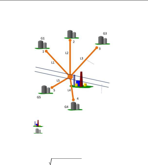
Laying of highways for gas transportation has an infinite number of options. Therefore the average option was conforeignred. The calculation scheme is shown in Fig. 1.
Shortest route
Natural gas main pipeline
Fig. 1. On selecting the location of a liquefied natural gas plant:
––liquefied natural gas plant;
—liquefied natural gas storage
As a liquefaction plant is assumed to be located near the main pipeline, the optimal governing parameters ( xopt ; yopt ) are identified given by the following system of equations:
|
|
n |
|
|
|
|
2 |
|
2 |
2q1 q2 mспгном 2mхладном nтр |
|
|
|
|
|
|
|
|
|
|
|
||
0, 01 1 0, 01D 1, 2 |
xi x |
|
yi y |
|
0 |
||||||
|
|
i 1 |
|
|
|
|
|
|
|
|
. (2) |
y |
2 х х1 y1 х х2 |
|
|
|
|
|
|
||||
у |
|
|
|
|
|
||||||
|
|
|
|
|
|
|
|
|
|
|
|
|
x2 x1 |
|
|
|
|
|
|
||||
|
|
|
|
|
|
|
|
|
|||
|
|
|
|
|
|
|
|
||||
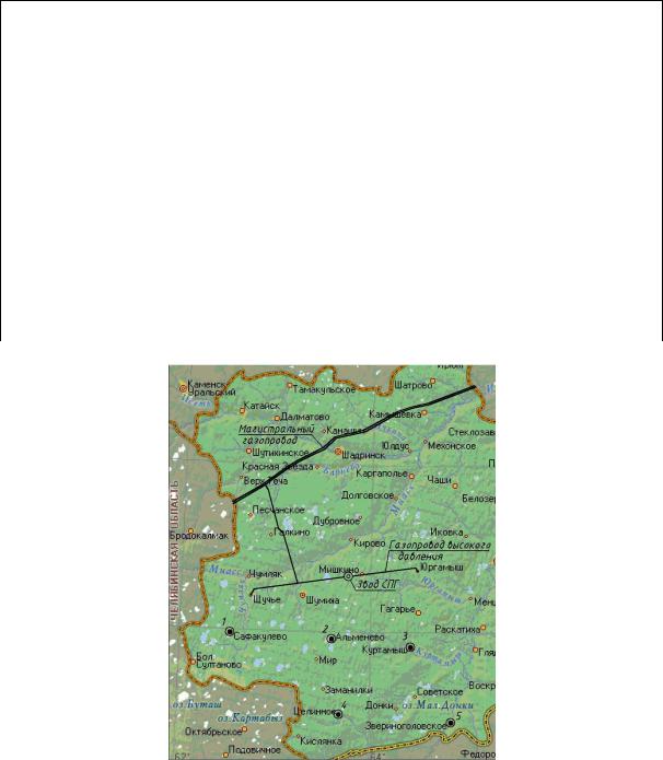
For numerical implementation of the mathematical model the corresponding calculations were performed for the Kurgan region. The initial data for the calculation are presented in Table 1 and the graphic representation in Fig. 2.
The location of the main pipeline in a gas supply area is specified with two point with the coordinates: (77,1;117,2), (182,6;130,9). As a result we get the following coordinates of a source: (137,4;125,1). In order to make calculations less challenging, the computer software was designed [4].
36
Issue № 4(32), 2016 |
ISSN 2075-0811 |
Table1
Coordinates of gas fuel consumers
Points in the main pipeline
|
Point №1 |
|
|
|
|
Point №1 |
|
|
|
|
|
|
|
|
|
х= |
77,1 km |
|
х= |
|
182,6 km |
|
|
|
|
|
|
|
|
|
|
у= |
117,2 km |
|
у= |
|
130,9 km |
|
|
|
|
|
|
|
|
|
|
|
|
Coordinates of places of reforeignnce |
|
|
|||
|
|
|
|
|
|
|
|
№ |
Name |
|
х, km |
|
|
|
у, km |
|
|
|
|
|
|
||
1 |
Safakulevo |
|
61,7 4355m3/h |
|
90,1 |
||
|
|
|
|
|
|
|
|
2 |
Almenevo |
|
126,4 |
5471m3/h |
|
83 |
|
|
|
|
|
|
|
||
3 |
Tselinnoe |
|
131 5918m3/hч |
|
35,4 |
||
|
|
|
|
|
|
|
|
4 |
Kurtamysh |
|
180,1 |
43021m3/h |
|
75,5 |
|
|
|
|
|
|
|
|
|
5 |
Zverinogolovskoe |
|
206,4 |
6730m3/h |
|
29,2 |
|
|
|
|
|
|
|
||
|
|
Coordinates of a liquefied natural gas plant |
|
|
|||
|
|
|
|
|
|
|
|
х= |
137,4 |
|
|
|
|
|
|
|
|
|
|
|
|
|
|
у= |
125,1 |
|
|
|
|
|
|
|
|
|
|
|
|
|
|
Fig. 2. Optimal location of a liquefied natural gas plant
Developing the original construction of an automobile tank for the transportation of liq-
uefied natural gas. As a result of the analysis of existing cryogenic equipment for liquid gas transportation to users remote from a network gas main pipeline, a new construction of a cryogenic tank was developed [5, 6]. The novelty of the suggested solution is an extra shell in a
37
Scientific Herald of the Voronezh State University of Architecture and Civil Engineering. Construction and Architecture
tank. This would allow the heat transfer to be reduced and the performance to be enhanced. A drawback of existing tanks for the transportation of liquefied natural gas is that as an automobile tank is in motion, a liquid mixes and heats up intensively. In many constructions transportation compartments are not sufficiently heat-insulated from the body of a tank and heat is transferred from the environment through partitions to the liquid resulting in evaporation losses of liquefied gas due to exterior heat sources thus reducing the transportation times. An automobile tank for storing and transporting liquefied natural gas developed by The Industrial Cooperation ―Scientific Industrial Company‖ ―EKIP‖ (http://www.ekip-projects.ru/9/9-1.shtml).
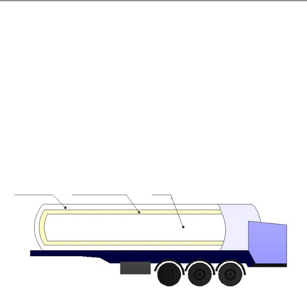
The task at hand is solved in the following manner: in a cryogenic tank with the major shell containing a vessel for the transportation of liquid gas an extra shell is recommended for designing and use its space for transporting cold carriers. Hence the space is between the major shells and vessel is filled with an insulator (Fig. 3).
Cold carrier |
|
Powder air insulation |
|
LNG |
|||
|
|
|
|
|
|
|
|
V = 14,2 m3 |
|
|
|
|
|
V = 16 m3 |
|
Fig. 3. Suggested model of a cryogenic tank
The tank operates according to the following cycle:
1.Its technical performance is tested and its heat is removed. For blowing nitrogen is supplied to a tank at the temperature higher than the boiling one of a cold carrier and then the tank is connected to external sources.
2.Liquefied natural gas is pressed from a foreign tank and stored for a while to evaporate in the sources and the pressure to drop. A gap between the exterior and extra shells is filled with a cold carrier.
3.Liquefied natural gas is transported (with the open valve ―pressurization-gas disposal‖).
4.Natural gas is supplied or the liquid phase is poured into the storage. Excessive pressure necessary for pouring is created by either LNG vapours (from the evaporator) or a foreign source.
38
Issue № 4(32), 2016 |
ISSN 2075-0811 |
5 The cool carrier is poured and then the tank is heated away (~ down to the temperature corresponding with that of the environment or partial heating down to the temperature of 218К).
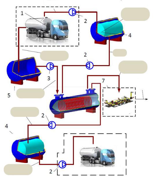
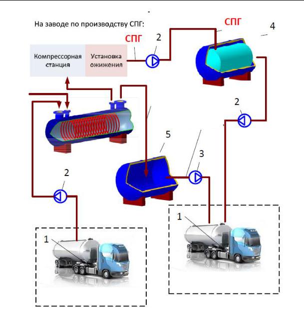
Original method of delivering LNG with getting the refrigeration potential back. Considering the growing energy prices, sustainability of the production and transportation of LNG in gas supply of remote places of residence seems very urgent. The solution of the energy-saving problem would be to improve particular components of a gas supply system in order to cut down the amount of wasted cold energy. Presently the refrigeration potential obtained during regasification of LNG is suggested to be used for preliminary cooling of natural gas during the liquefaction stage in a gas production plant [7]. Fig. 4 presents the scheme for this method of gas liquefaction.
LNG
LNG and heated cold carrier supply
LNG
Heated cold carrier
Regasified gas
Network natural gas
Heated cold carrier |
|
|
Reduction |
Cooled cold carrier |
block |
Cooled cold carrier |
Cool carrier pouring area |
|
39
Scientific Herald of the Voronezh State University of Architecture and Civil Engineering. Construction and Architecture
|
|
|
|
|
LNG |
LNG production plant |
|
|
|||
|
|
|
|
|
|
|
|
|
|
|
|
|
|
|
LNG |
|
|
|
|
|
|
|
|
Compression |
Fluidization |
|
|
|
|
station |
setup |
|
|
|
|
|
|
|
|
|
|
Heated cold carrier
Heated cold carrier
LNG and heated cool carrier pouring area
Cool carrier supply area
Fig. 4. Scheme of delivering liquefied gas:
а) scheme of delivering LNG from the user to the liquefaction device: b) scheme of delivering LNG from the the liquefaction device to the user 1 –– cryogenic tank; 2 –– cryogenic pump; 3 –– a cold carrier transit pump;
4 –– LNG storage capacitor; 5 –– a cold carrier storage capacitor; 6, 7 –– heat exchanger
The original method of delivering gas is performed in the following way:
––liquefied natural gas preliminarily prepared in a heat-exchanger 6 is supplied into a liquefication block and fed into a liquefied natural gas storage;
––from liquefied natural gas storage the liquid phase is pumped into a cryogenic tank [6] using a pump 2 and the cool carrier is pumped into the space between the shells of the tank (the temperature of the cool carrier is about –– 27°С for the cold season);
40