

3202
.pdfIssue № 3 (35), 2017 |
ISSN 2542-0526 |
Hence the iteration looks as follows
нов |
|
|
0.5 sin2 Nucos2 |
(9) |
|
n |
|
0.5sin2 |
. |
||
|
|
|
ст |
|
|
The initial μn is specified using the range
n 1 n n 1 2 .
The calculation ends as soon as the previously specified accuracy (error) ε is achieved, e.g., when the following equality holds true
нов ст |
0.000001 . |
(10) |
The criterion for the efficiency of the model was the Gaussian function that is the following for the first option
|
N T |
j T V j |
2 |
, |
(11) |
|
|
оп |
00 |
|
|
|
|
j 1
where the expression in the square brackets of the right part of the formula (4) is denoted using V(j) for the experimental value τ = τ(j); N is the number of the experimental measurements τ(j) and Топ (j).
Differentiating the function (11) using Т00 and equating the derivative to zero we get
|
N |
|
|
T00 |
Tоп j V j |
. |
(12) |
N |
|||
|
j 1 |
|
|
V j V j
j 1
The identification using the scheme (see Fig. 2) was performed for all the options of the model using the algorithmic language. The results are presented below.
Option 1. The characteristic equation is (5), the solution is (4). The optimal values are T00 = 12.64861, Nu = 0.9997329, u1 = 0, u2 = 0.3059973, u3 = 0.1100073. The Gaussian function is Ф = 737.8488.
Option 2. The characteristic equation is
|
|
|
|
|
|
|
n ctg n |
N u . |
|
|
|
|
|
|
||||
The solution is |
|
|
|
|
|
|
|
|
|
|
|
|
|
|
|
|
|
|
|
|
|
|
|
2 |
Nu2 |
|
|
|
|
|
|
|
a |
2n2 |
|
|
|
T x, T00 1 |
2 |
|
|
|
n |
|
|
|
|
|
1 cos n sin |
|
n x u e |
|
l |
|
for u ≠0, |
|
|
|
2 |
|
2 |
|
|
|
|
l |
|
||||||||
|
n 1 |
|
n |
Nu Nu |
|
n |
|
|
|
|
|
|
||||||
|
|
|
|
|
|
|
|
|
|
|
|
|||||||
11

Russian Journal of Building Construction and Architecture
|
|
Nu |
|
x |
|
|
|
|
2 |
Nu2 |
|
|
|
|
|
|
a |
2n2 |
|
|
T x, T00 1 |
|
|
|
|
2 |
|
|
|
n |
|
|
|
|
sin |
|
n xe |
|
l |
|
for u =0. |
|
|
|
|
2 |
|
2 |
|
|
n |
|
|
|||||||||
|
|
1 Nu l |
n 1 |
|
n |
Nu Nu |
|
|
l |
|
|
|
|
|
||||||
|
|
|
|
|
|
|
|
|
|
|
|
|||||||||
The optimal values are T00 =–8.994679, Nu =0.500151, u1 =0, u2 =0.30388, u3 =0.101292. The Gaussian function is Ф=3542.8.
Option 3. The characteristic equation is
|
|
|
|
|
|
|
tg |
|
|
2Nu 2 |
. |
|
|
|
|
|
|
|
|
|
|
|
|
|
|
|
|
|
n |
|
n |
|
|
|
|
|
|
|
|
|
|||
|
|
|
|
|
|
|
n2 Nu2 |
|
|
|
|
|
|
|
|
||||||
|
|
|
|
|
|
|
|
|
|
|
|
|
|
|
|
|
|
|
|||
The solution is |
|
|
|
|
|
|
|
|
|
|
|
|
|
|
|
|
|
|
|
|
|
|
|
|
|
|
|
|
n2 Nu2 cos n |
|
|
|
|
Nu |
|
|
|
||||||
|
|
|
a |
2n2 |
|
|
cos |
ln l u |
|
n |
sin |
ln l u |
|||||||||
T l, T00 |
1 |
2Nu e |
|
l |
1 |
|
|
2 |
|
|
2 |
|
|
|
|
|
|
|
|
. |
|
|
|
|
Nu |
|
2 |
Nu |
2 |
2Nu |
|||||||||||||
|
|
n 1 |
|
|
|
|
n |
|
|
n |
|
|
|||||||||
|
|
|
|
|
|
|
|
|
|
|
|
|
|
|
|
|
|
|
|
|
|
|
|
|
|
|
|
|
|
|
|
|
|
|
|
|
|
|
|
|
|
|
|
The optimal values are
T00 16.00909, Nu 1.04837, u1 0, u2 0.309943, u3 0.0980236.
The Gaussian function is Ф = 1092.762.
Comparing three investigated options of the models we can see that the efficiency criterion (the sum of the roots of the deviations of the values of T(x, l) from the calculated ones) has the smallest value for the first variant: Ф = 737.8488. The values of the unknown parameters of the mathematical model should be as according to the results for this particular variant, i.e.
T00 12.69782, Nu 0.9997329, u1 0, |
0 t 7 min, |
u2 0.3059973, 7 t 22 min, u3 0.1100073, 22 t 92 min.
Therefore the model of heating the water in a heat-transferring pipe is obtained and identified.
3. Calculating the temperature field in a storage tank
In order to calculate the temperature of the water in a storage tank depending on the time and coordinate, we solve the equation of heat conductivity [11, 13]:
T |
uб |
T |
a |
2Т |
|
(13) |
t |
z |
z 2 |
||||
б |
|
б |
|
|
б |
|
for a semi-restricted environment (z ≥ 0) for the boundary condition
Тб z,t |
|
z 0 |
f t , |
(14) |
|
||||
|
|
|
|
where f(t) is the temperature of the water in the pipe at the storage tank inlet (z = 0) calculated based on the initial temperature Т0.
Тб z,0 T0 . |
(15) |
12
Issue № 3 (35), 2017 |
ISSN 2542-0526 |
Further on the temperature of the water in a storage tank will be calculated based on Т0 so that at the initial point in time in the entire area
Тб z,0 0.
For the function f(t) the dependence is previously obtained (4).
Т00 |
12.6486; |
Nu 0.9997; |
|
|
|||
|
|
0 for |
0 t |
t2 7 min; |
|
|
|
u u1 |
|
|
|||||
|
|
0.306 |
m/sec |
for |
t2 t t3 22 min; |
||
u u2 |
|||||||
u u |
0.11 m/sec |
for t |
t t |
4 |
92 min. |
||
|
3 |
|
|
|
3 |
|
|
In the equation (13) the rate of the water in the tank is denoted using uб: u б k б u
for a continuous flow
kб kS Sтр , Sб
(16)
(17)
(18)
where Sтр, Sб is the area of the heat-transferring pipe and tank respectively, m2.
Using the influence function [2] the solution of the equation (13) for the boundary condition (14) and the initial condition (16) is as follows
|
|
1 t z uб t |
|
z u |
t 2 |
|
|
|||
Tб z,t |
|
|
|
б |
|
|
|
|||
|
|
4a t |
f ( )d . |
(19) |
||||||
|
|
t0 |
|
e |
|
|
|
|||
2 |
a |
t 3/2 |
|
|
|
|||||
The integration (19) was performed numerically using the rectangle rule. The calculation of the temperature of the water in the tank according to the formulae (19), (4) is implemented using the algorithmic language. The statistical evaluation based on the Fisher criterion shows that the equation (19) is good at describing the dependence the temperature of the water at the storage tank outlet on the time. Note that the function f(t) as well as the experimental values of the temperature of the water in the pipe at the tank inlet is approximated using the linear dependence
f t A Bt , |
(20) |
where А = 75.968, В = 0.1391, for t > 22 min.
Then for solving the task (13) for the conditions (14), (15) we use the analytical dependence obtained [3, 17] by means of the operational method (the Laplace transformation) that is as follows:
|
|
Тб z,t |
1 |
|
|
|
* |
z u t |
|
|
uбz |
|
* z u t |
|
|
|
|||||||||
|
|
|
|
|
|
|
|
|
|||||||||||||||||
|
|
2 |
A |
Ф |
|
|
б |
|
|
|
e a Ф |
|
|
|
б |
|
|
|
|||||||
|
|
|
2 at |
|
|
|
|
||||||||||||||||||
|
|
|
|
|
|
|
|
|
|
|
|
|
2 at |
|
|
|
(21) |
||||||||
|
В |
|
|
|
uбz |
|
|
z u t |
|
|
|
|
|
|
|
* z u t |
|||||||||
|
|
|
|
* |
|
|
|
|
|
|
|
||||||||||||||
|
|
|
|
|
|
|
|
|
|
|
|
||||||||||||||
|
|
|
z uбt e a Ф |
|
|
|
б |
|
|
z uбt Ф |
|
|
б |
|
|
t. |
|||||||||
|
|
|
2 at |
2 at |
|
||||||||||||||||||||
|
2uб |
|
|
|
|
|
|
|
|
|
|
|
|
|
|
|
|
||||||||
13

Russian Journal of Building Construction and Architecture
In (21) an extra error function is denoted using Ф*(х):
Ф* х 1 Ф х , |
(22) |
|||
Ф х |
2 |
х е 2 d . |
(23) |
|
|
||||
|
0 |
|
||
The error function (the probability integral) (23) can be presented as an evenly convergent series:
|
2 |
|
|
|
|
|
|
|
|
1 n x2n 1 |
|
Ф х |
|
n 0 |
2n 1 n!. |
(24) |
|
|
|||||
The experiment of calculating the error function shows that for х < 1 in order to obtain the results with the error of less than 0.000001 in the expansion (24), only 3 members have to be sustained, i.e. to approximate this function using the following polynomial:
Ф x |
2 |
|
x |
3 |
|
x |
5 |
|
|
x |
|
|
|
. |
(25) |
||||
|
3 |
|
|
||||||
|
|
10 |
|
|
|||||
The results of the calculations of the temperature using the formulae (21) and (19) are no more than 8 % different from each other.
Fig. 3 shows the results of theoretical and experimental studies of charging the heat accumulator.
Теmperature, оС
100 |
|
|
|
90 |
|
|
|
I |
|
|
|
80 |
|
|
|
|
|
|
|
70 |
|
|
|
60 |
|
|
|
|
|
|
|
50 |
|
|
II |
|
|
|
|
40 |
|
|
|
|
|
|
30
20
10
0
0 |
5 |
10 |
15 |
20 |
25 |
30 |
35 |
40 |
45 |
50 |
55 |
60 |
65 |
70 |
75 |
80 |
85 |
90 |
95 |
Time, min
Fig. 3. Change in the temperature of the water in the storage tank: I at the tank inlet; II at the tank outlet;
 is a theoretical one;
 is an approximated one
14
Issue № 3 (35), 2017 |
ISSN 2542-0526 |
Conclusions
1.The mathematical models to describe the convection heat exchange in the storage tank are developed. The optimal parameters when the model becomes sufficient for the experiment are obtained using identification.
2.The best model for heating water in a heat-transferring pipe using a Gaussian function as a criterion.
3.By means of mathematical modelling, analytical dependences to determine the temperature at the storage tank inlet and outlet are obtained.
4.A simplified mathematical model for charging the heat accumulator is also obtained.
References
1.Al'tshul'A. D., Zhivotovskiy L. S., Ivanov L. P. Gidravlika i aerodinamika [Hydraulics and aerodynamics]. Moscow, Stroyizdat Publ., 1987. 414 p.
2.Budak B. M., Samarskiy A. A., Tikhonov A. N. Sbornik zadach po matematicheskoy fizike [Collection of problems on mathematical physics]. Moscow, Nauka Publ., 1972. 688 p.
3.Karslou G., Eger D. Teploprovodnost' tverdykh tel [The thermal conductivity of solids]. Moscow, Nauka Publ., 1964. 488 p.
4.Kitaev D. N. Vliyanie sovremennykh otopitel'nykh priborov na regulirovanie teplovykh setey [The impact of modern heating devices for regulation of heat networks]. Nauchnyy zhurnal. Inzhenernye sistemy i sooruzheniya, 2014, vol. 2, no. 4 (17), pp. 49—55.
5.Kitaev D. N., Kurnosov A. T. Issledovanie znacheniy kpd mini-TETs. [The study values the efficiency of CHP plants]. Vestnik Voronezhskogo gosudarstvennogo tekhnicheskogo universiteta, 2008, vol. 4, no. 12, pp. 71—73.
6.Kitaev D. N., Zolotarev A. V., Shestykh N. S. Perspektivnye skhemy ispol'zovaniya kogeneratsionnykh ustanovok v sistemakh teplosnabzheniya [The future plan of the use of cogeneration in heat supply systems].
Nauchnyy zhurnal. Inzhenernye sistemy i sooruzheniya, 2012, no. 2 (7), pp. 26—29.
7.Kitaev D. N. Pogreshnost' rascheta temperaturnogo grafika teplovoy seti pri ispol'zovanii pokazateley otopitel'nykh priborov [The error of calculation of the temperature schedule of the heat network during the use of the indicators of heating appliances]. Promyshlennaya energetika, 2013, no. 7, pp. 37––37.
8.Kitaev D. N. Raschet temperatury naruzhnogo vozdukha v tochke izloma temperaturnogo grafika [Calculation of air temperature in the inflection point temperature chart]. Novosti teplosnabzheniya, 2012, no. 10 (146), pp. 46––48.
9.Kitaev D. N. Sovremennye otopitel'nye pribory i ikh pokazateli [The modern heating devices and their performance]. Santekhnika, otoplenie, konditsionirovanie, energosberezhenie, 2014, no. 1, pp. 48––49.
10.Lapchik M. P., Ragulina M. I., Khenner E. K. Chislennye metody [Numerical methods]. Moscow, Akademiya Publ., 2004, 384 p.
15

Russian Journal of Building Construction and Architecture
11.Mel'kumov V. N., Kuznetsov S. N. Vzaimodeystvie ventilyatsionnykh vozdushnykh potokov s konvektivnymi potokami ot istochnikov teploty [The interaction of ventilation air flows with convection flows from heat sources]. Izvestiya vuzov. Stroitel'stvo, 2009, no. 1, pp. 63—69.
12.Mel'kumov V. N., Kuznetsov I. S., Kobelev V. N. Vybor matematicheskoy modeli trass teplovykh setey [The choice of the mathematical model tracks thermal networks]. Nauchnyy vestnik Voronezhskogo GASU. Stroitel'stvo i arkhitektura, 2011, no. 2, pp. 31––36.
13.Mel'kumov V. N., Kuznetsov I. S. Dinamika formirovaniya vozdushnykh potokov i poley temperatury v pomeshchenii [Dynamics of formation of air streams and temperatures fields in premise]. Nauchnyy vestnik Voronezhskogo GASU. Stroitel'stvo i arkhitektura, 2008, no. 4, pp. 172––178.
14.Mel'kumov V. N., Kuznetsov I. S., Kobelev V. N. Zadacha poiska optimal'noy struktury teplovykh setey [The task of finding the optimal structure of heat networks]. Nauchnyy vestnik Voronezhskogo GASU. Stroitel'stvo i arkhitektura, 2011, no. 2, pp. 37––42.
15.Mel'kumov V. N., Loboda A. V., Chuykin S. V. Matematicheskoe modelirovanie vozdushnykh potokov v pomeshcheniyakh bol'shikh ob"emov [Mathematical modelling of air flows in premises of large volumes].
Nauchnyy vestnik Voronezhskogo GASU. Stroitel'stvo i arkhitektura, 2014, no. 2 (34), pp. 11––18.
16.Mel'kumov V. N., Kuznetsov I. S. Matematicheskoe modelirovanie poley kontsentratsiy vrednykh veshchestv pri proizvodstve stroitel'nykh materialov [Mathematical modeling of fields of concentrations of harmful substances in the manufacture of building materials]. Nauchnyy vestnik Voronezhskogo GASU. Stroitel'stvo i arkhitektura, 2013, № 1 (29), pp. 99—107.
17.Mel'kumov V. N., Kuznetsov S. N., Gulak V. V. Modelirovanie zadymlennosti pomeshcheniy slozhnoy konfiguratsii v nachal'noy stadii pozhara [Modeling of smoke content of premises of complex configuration at initial stage of fire]. Nauchnyy vestnik Voronezhskogo GASU. Stroitel'stvo i arkhitektura, 2010, no. 3, pp. 131—
18.Mel'kumov V. N., Chuykin S. V., Papshitskiy A. M., Sklyarov K. A. Modelirovanie struktury inzhenernykh setey pri territorial'nom planirovanii goroda [Modeling of the structure of utility networks the regional planning city]. Nauchnyy vestnik Voronezhskogo GASU. Stroitel'stvo i arkhitektura, 2015, no. 2 (38), pp. 41––48.
19.Muchnik G. F., Rubashov I. B. Metody teorii teploobmena. Teploprovodnost' [Methods of the theory of heat transfer. The thermal conductivity]. Moscow, Vysshaya shkola Publ., 1970. 288 p.
20.Sheffe G. Dispersionnyy analiz [Analysis of variance]. Moscow, Nauka. Gl. red. fiz.-mat. lit. Publ., 1980.
512p.
21.Hadia N. M. A., Ryabtsev S. V., Seredin P. V., Domashevskaya E. P. Effect of the temperatures on structural and optical properties of tin oxide (SnO x) powder. Physica B: Condensed Matter, 2010, vol. 405, iss. 1, pp. 313–
317.doi: 10.1016/j.physb.2009.08.082.
16

Issue № 3 (35), 2017 |
ISSN 2542-0526 |
TECHNOLOGY AND ORGANIZATION OF CONSTRUCTION
UDC 691-404-033.265
P. G. Kudryavtsev1, O. L. Figovskii2
ORGANIC WATER-SOLUBLE SILICATES FOR PROTECTIVE COATINGS
Holon Institute of Technology (HIT)
Israel, Holon, tel.: +972-52-736-5647, e-mail: pgkudr89@gmail.com 1PhD in Chemistry, Prof.
Israel Research Center Polymate Ltd
Israel, Migdal HaEmek, tel.: +972-52-736-5647, e-mail: figovsky@gmail.com 2D. Sc. in Engineering, Prof.,
Foreign Member of the Russian Academy of Architecture and Building Science
Statement of the problem. Coatings are resistant to corrosive media, which is necessary for the protection of buildings, facilities and equipment operating in aggressive environments. Such a problem can be solved by using polymer-silicate nanocomposites based on organic silicates. The aim of this work is to study the properties and to compare binders based on liquid glass and silicate containing strong organic bases.
Results. The paper describes the properties of organic-soluble silicates and their use for the preparation of nanocomposite materials. Obtaining technology and properties of soluble systems with high silicate modulus has been analyzed. Advantages of strong organic bases silicates for the preparation of heat resistant nanocomposites have been shown. Ways of obtaining quaternary ammonium silicates and their use for the manufacture of nanocomposites have been proposed. Modifiers for designing hybrid nanostructured composite materials using a sol-gel process have been proposed. It is shown that the structuring phenomenon allows one to predict some aspects, synthesis and application of hybrid materials based on silica with grafted polymers. Possibility of modifying compositions using nanostructured agents such as tetrafurfuryloxysilane was demonstrated.
Conclusions. In this paper we demonstrated the possibility of using organic silicates for the production of new nanocomposite materials for protection and covering of buildings, facilities and equipment of various external factors.
Keywords: polymersilicate nanocomposite materials, liquid glass, quaternary ammonium silicates, silicates strong organic bases, tetrafurfuryloxysilane, nanostructuring agents.
Introduction
Despite the development of new types of corrosion resistant materials, i.e. special types of steel, polymer composites, glass plastics, etc., materials based on liquid glass are remaining
© Кudryavtsev P. G., Figovsky О. L., 2017
17

Russian Journal of Building Construction and Architecture
common [1, 4, 17]. It is due to the fact that new effective polymer materials are costly, limited and labour-intense, highly toxic and do not have a necessary resource base. Acid resistant materials prepared based on liquid glass are not like that.
The major types of acid resistant materials are acid resistant cements, mastics, concrete and surfacings. Acid and chemically strong surfacings are classed into two groups: polymer concrete prepared with synthetic resin (furan, polyester, carbamide, etc.) and polysilicate composite surfacing based on natrium or potassium liquid glass.
Polysilicate composite surfacings are obtained using acid resistant fillers of different granulometric composition. A large filler is crushed granite, finely ground filler is quartz sand, solidification catalyzer is hexafluorosilicate and special additives of plasticizers, sealants, water repellent components, etc. [1]. Acid resistant quartz cement based on natrium hexafluorosilicate is most common in industry. It is a mix that consists of fine quartz sand and natrium hexafluorosilicate. The mix is sealed with potassium or natrium liquid glass and following being burnt in the air there is an acid resistant stone. The content of natrium hexafluorosilicate in the material is 4 % (first type material for acids) or 8 % according to the weight (second type material for acids, solutions). Acid resistant quartz materials based on natrium hexafluorosilicate are used for laying facing from chemically strong materials (brick, tile), protecting buildings, chemical equipment as well as manufacturing acid resistant surfacings.
The most daunting task is to protect chemical equipment operating with 70% sulphuric acid at the boiling temperature. Such processes are widely employed in fine chemical technology, e.g., for decarboxylation of organic acids, saponification of esters, depolymerization of polyesters, etc. In order to protect such equipment, we developed a composition that contains fine ground zircon ZrSiO4 (88 %), hexafluorosilicate (2 %) and liquid glass (10 %). Such a composition actually lasts for up to 50 cycles in a medium of 70% sulphuric acid with the cycle time of 10—12 hours.
Lately there have been efforts made to develop applied silicate polymer composites that are water-soluble silicates with additives of active substances of the furan type. They operate in acid and neutral media and at extremely high temperatures. They are cheap and easy to prepare, not toxic, not combustible. The cost of polymer silicate materials is compared with that of cement concrete and is several times lower than that of polymer concrete. Silicate polymers such as concrete, construction solutions, mastics are used to prepare a variety of structures (monolith as well as facing). It is potentially promising to develop composites based on a liquid glass binder modified by substances based on furfuryl alcohol.
18
Issue № 3 (35), 2017 |
ISSN 2542-0526 |
A considerable increase in the strength, heat and fire resistance of a silicate matrix is achieved by introducing ethers of orthosilicate acid and furfuryl alcohol (tetrafurfuryloxysilane). This is due to stronger contacts between silica gel globules and modification of the alkaline component owing to an “injection” of a furan radical. Introduction of a binder, a tetrafurfuryloxysilane additive results in nanoparticles of SiO2 and furfuryl alcohol that fills the matrix and forms a cross-linked polymer. These particles act as centres of nucleation and crystallization. Adding tetrafurfuryloxysilane enhances the mechanical and chemical strength of a binder and this is what is commonly done to prepare acid resistant surfacings [7, 11].
In order to increase the strength, acid resistance, thermal resistance and fire resistance of construction materials and structures, tetrafurfuryloxysilane is introduced into a composite binder. It is synthesized by interesterification of tetraethoxysilane and furfuryl alcohol.
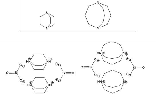
The obtained binder contains the following: liquid glass — 80—95 mass %; tetrafurfuryloxysilane — 2—7 mass %; solidifier, natrium hexafluorosilicate — 13 mass %. Therefore some of the liquid glass is an organic alkaline liquid glass. In this product 1.4-diazobicycle [2.2.2] octane -1.4-diumsilicate or 1,5- diazobicycle [3.3.3] undecane-1.5-disilicate with the proportion of 2—4 mass % are used as an organic component (Fig. 1).
а)
b)
Fig. 1. Structural formulas:
а) 1.4-diazobicycle [2.2.2] octane and 1.5- diazobicycle [3.3.3] undecane;
b) 1.4-diazobicycle [2.2.2] octane -1.4-diumsilicate and 1.5- diazobicycle [3.3.3] undecane-1.5-disilicate
19

Russian Journal of Building Construction and Architecture
Water-soluble silicate containing an organic cation of an alkali metal is obtained by means of interaction of a salt of an organic derivative of quaternary ammonium with amorphous silica. Soluble organic alkali silicates such as tetrabutylammonium silicate were used as components for self-extinction of a binder [2, 9].
The suggested nanostructuring binder was prepared using laminar mixing of liquid glass containing cations of alkali metals such as natrium. Tetrabutylammonium silicate and watersoluble silicate containing an alkali organic cation were added to the obtained composition [5]. After mixing of all the components of the binder it has to be used within 2 or 3 hours. A solidifier was added along with a finely ground mineral filler.
Introducing a binder of a nanostructuring component of tetrabutylammonium silicate results in nanoparticles of SiO2 and furfuryl alcohol. The nanoparticles of SiO2 acts as centres of nucleation and crystallization. The resulting furfuryl alcohol fills the silica matrix, fails and polymerizes. Adding tetrafurfuryloxysilane enhances the mechanical and chemical strength of materials based on a composite binder. It is widely used in preparing acid resistant surfacings. Liquid glass with these organic silicates is in agreement with water dispersion of chloroprene rubber and polyurethane as well as most synthetic latexes based on synthetic rubber. These composites based on mutually penetrating non-organic and organic polymer grids are described in papers [19, 20].
1. Synthesis of silicates of organic compounds
An important aspect of making good use of silicates of strong organic compounds is to develop of a simple and effective method of their synthesis based on available and fairly cheap initial substances. We came up with a new method of synthesing these compounds. It employs silicates as original raw material for synthesing organic silicates.
During interaction of silicic ashes with strong organic compounds they are stabilized only by charging their surface. For that рН has to reach 9. In these conditions stable silicate systems with a high content of silicate dioxide and a modulus SiO2:M2O. In this case the resulting silicate modulus depends only on the diameter of particles of ashes. This dependence is shown in Fig. 2.
In fact Fig. 2 shows a diagram of states of a silicate system with strong organic compounds. The field of the diagram that lies between the drawn line and axis d (nm) corresponds with the area where there might be stable colloid polymer and monomer silicate systems. Above this line the corresponding silicate systems undergo quick coagulation and gel formation. Therefore for ashes of silicate dioxide the suggested range of particle size d is from 7 to 8 nm and for a theoretically possible silicate modulus SiO2:M2O it is from 17 to 19.
20