

2918
.pdfIssue № 1 (37), 2018 |
ISSN 2542-0526 |
UDC 624.04
S. B. Kositsyn1, V. S. Fedorov2, V. Yu. Akulich3
GEOTECHNICAL PROJECTION OF THE INFLUENCE OF THE CONSTRUCTION OF THE DESIGNED METROPOLITENE TUNNEL BY THE METHOD
OF SHIELD PASSAGE ON THE SEDIMENTATION OF THE EARTH’S SURFACE
Moscow State University of Railway Engineering Nicolay II (MIIT) Russia, Moscow, tel.: (499) 978-16-73, e-mail: kositsyn-s@yandex.ru 1D. Sc. in Engineering, Prof., Head of the Dept. of Theoretical Mechanics
2D. Sc. in Engineering, Prof., Head of the Dept. of Engineering Construction, Buildings and Structures 3PhD student of the Dept. of Theoretical Mechanics
Statement of the problem. The work is aimed at a geotechnical forecast of the influence of the construction of the tunnel on the change in the stress-strain state of the surrounding soil mass, namely, the precipitations that arise on the surface of the earth. The work assumes both a numerical and an analytical solution with subsequent comparative analysis.
Results. As a result of the carried out research, the authors carried out a geotechnical forecast of the influence of the construction of tunnel on the change in the stress-strain state of the surrounding soil massif, namely, the precipitations arising on the surface of the earth with the help of a specially designed computational model.
Conclusions. As a result of the work carried out by the authors, a technique has been developed that makes it possible to determine the sediments of the Earth's surface during the progress of the slurry shield by the finite element method due to the use of GAP contact elements. To analyze the obtained result, a calculation of the Earth's surface sediment was made during the advancement of the tunnel mechanized complex according to the analytical method. The calculation results obtained by means of the numerical and analytical method are in good agreement with each other both qualitatively and quantitatively, which indicates the reliability of the constructed models and calculations.
Keywords: tunnel, soil massif, geotechnics, slurry shield, sedimentation mold, flat end contact finite elements.
Introduction. The objective of the paper is geotechnical forecast of the influence of construction of an interstation tunnel on changes in the stress-strain of a surrounding soil massive, i.e. on resulting heavings on the Earth’s surface.
© Коsitsyn S. B., Fedorov V. S., Аkulich V. Yu., 2018
81

Russian Journal of Building Construction and Architecture
During the use of an interstation tunnel powered complex (shield tunnelling) on an area of a tunnel that is fastened or partially fastened, there is a displacement of a rock in the direction towards a tunnel. Therefore the amount of rocks extracted from an underground space is invariably larger than in theory as calculated using a project profile of a tunnel. An extra amount of rocks extracted from an underground space is called “a lost amount” and determined using the parameter V that is a ratio of the amount of the extracted rocks to the tunnel itself (determined using the external diameter of the tunnel).
A lost amount is a measurement of a failure of a massive as a result of tunneling works and causes development of a trough of heaving of the Earth’s surface. In order to solve the problem, it is necessary to design a calculation model of a tunnel with a surrounding soil massive that would allow the amount of extra lost soil extracted from an underground space during the use of an interstation powered complex to be taken into account followed by the analysis of the obtained stress-strain of the system and comparison of the results with the analytical method of identifying heaving. Modelling and calculations are performed using a modern finite-element software MSC PATRAN — NASTRAN in geometrically and physically non-linear tasks.
1. Determining the heaving of the Earth’s surface during the use of an interstate tunneling powered complex by means of a numerical method. Based on the calculation complex
MSC PATRAN — NASTRAN, a method of finite elements that allow a mathematical modeling of the processes in the soil. The results of the calculations of the stress-strain are presented as tables as well as graphs [5].
A massive is considered continuous for tasks solved using the finite element method. This condition is met by the fact that elements stay in contact during deformation. Deformation of an element is due to the application of adjoining elements or external impacts of node forces each of which is split into two components along the coordinate axis. As a result, there is an equation in the matrix form that connects the known external forces with unknown displacements of the nodes through a rigidity matrix of the element. After determining node deformations according to the known ratios of the elasticity theory, deformations and stresses inside the elements are found [3, 6, 7].
The calculations of heaving of the Earth’s surface are performed for a falt task. Table 1 presents the major physical and mechanical properties of the soil.
The tunnel is designed in monolith ferroconcrete using concrete V45 and reinforcement A240, A400. The geometric characteristics of the liner ring of an interstate tunnel are as follows:
––external diameter, mm, — 5800;
––internal diameter, mm, — 5300;
82
Issue № 1 (37), 2018 |
ISSN 2542-0526 |
––average length of the liner ring along the tunnel, mm, — 1400;
––thickness of the block, mm, — 250;
––distance between the soil and external surface of the liner, mm, — 50.
|
|
|
Table |
|
Physical and mechanical characteristics of soils |
|
|
|
|
|
|
Description of the soils |
Deformation modulus E, МPа |
Poissoin coefficient ν |
Density, kg/m3 |
Fill-up soil |
13 |
–– |
1920 |
|
|
|
|
Pulverescent loams |
22 |
0.37 |
2080 |
|
|
|
|
Sandy loams |
27 |
0.35 |
2160 |
|
|
|
|
Sandy loams |
27 |
0.35 |
2120 |
|
|
|
|
Pulverescent sands |
30 |
0.31 |
2000 |
|
|
|
|
Fine ands |
33 |
0.3 |
2010 |
|
|
|
|
First for performing a calculation using a geotechnic forecast of changes in the stress-strain of a soil massive caused by the construction of a designed interstate tunnel using an interstate tunnel powered complex in the calculation software MSC PATRAN — NASTRAN, it is necessary to design a geometric scheme of a calculation model [9].
The geometric scheme of the calculation model is developed based on the initial data on construction solutions of a designed object and of engineering and geological findings.
In order to use the area for calculations, a strip with the width 1.4 m is identified (equal to that of the liner ring of a tunnel under construction). The examined area of the tunnel is modeled with straight beam finite elements with six degrees of freedom in each node. The areas of the soil are approximated using four-node flat finite elements with six degrees of freedom in each node as well. In order to model a contact between the external wall of the lining of the tunnel and surrounding soil, contact elements were used that allow an initial gap to be specified (in the software complex NASTRAN they are called GAP-elements), which allowed an extra amount of soil to be taken out that emerges as an interstate tunnel powered complex is moving along owing to a gap between the external wall of the tunnel lining and surrounding soil. These elements did not have zero lengths and tended to a zero tense rigidity. Their tense rigidity tended to infinity. An initial gap was accepted to be 50 mm. The calculation area was fastened from movements normal to the massive surface, along the faces, sides and bottom. The shell along the faces has identical support fastenings that provide a geometric unchangeability of the calculation model [2, 8, 20].
83
Russian Journal of Building Construction and Architecture
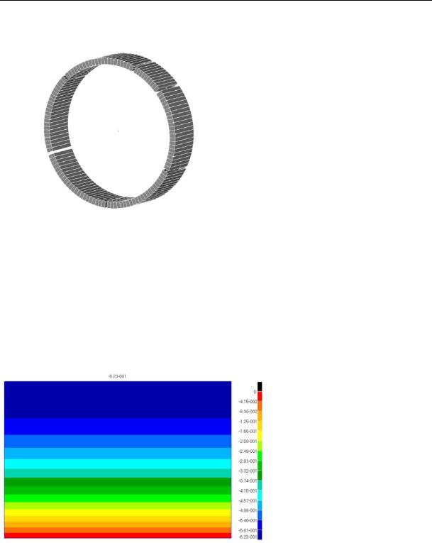
Fig. 1 presents a finite element model of the tunnel lining.
Fig. 1. Finite element model of the tunnel lining
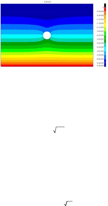
The calculation was performed in a non-linear setup (contact efforts are determined using the method of sequential approximations) and divided into two stages. At the first stage an initial stress-strain of the soil caused by its own state was determined; at the second stage the final stress-strain of the soil after the erection of the tunnel with loads of its own weight and that of the tunnel lining was determined. Fig. 2 and 3 present fields of vertical movements in the soil massive as a result of the first and second stages of the calculations respectively.
Fig. 2. Fields of the vertical movements of the soil massive according to the results of the fist stage of the calculations
A maximum heaving over the axis of the tunnel following the drive was 13.0 mm (it was obtained as the difference between heavings of the final and the domestic state).
Note that if contacts elements like GAP that allow for the extraction of an extra amount of the soil (creating a gap) that takes place as the interstate tunneling powered complex moves forward, the calculation model behaves not quite correctly and does not yield an actual field of vertical
84
Issue № 1 (37), 2018 |
ISSN 2542-0526 |
movements of the soil massive [1, 4] (the surface of the soil rises and no heaving occurs). For the comparative analysis of the obtained result the heaving of the Earth’s surface was calculated as the interstate tunneling powered complex is moving forward according to the analytical method.
Fig. 3. Fields of vertical movements of the soil massive according to the results of the second stage
of the calculations
2. Аnalytical method of determining heaving of the Earth’s surface due to “the loss of a volume” of the soil. A generalized semiempirical method of determining the heaving of the Earth’s surface for the construction of a single tunnel in homogeneous rocks was suggested by Attewell and Woodman [11, 12]. A trough of heaving of the Earth’s surface (Fig. 4) forming as a result of the construction of the tunnel can be described using the dependence
|
V |
|
x2 |
|
y y |
|
|
y xy f |
||
|
2i2 |
i |
||||||||
S |
s |
e |
x |
G |
|
|
G |
|
||
2 ix |
ix |
|
ix |
|||||||
|
|
|
|
|
|
|
|
|||
|
, |
(1) |
|
|
|
where S is heaving of the Earth’s surface at the point (x, y); x is the distance between the point in question to the transverse axis of the tunnel; y is the coordinate of the point along the transverse axis of the tunnel; Vs is a net volume of the trough of heaving of the Earth’s surface; yi is an initial position of the tunnel; yf is the location of the brow of the bottom; ix is the width of the trough of heaving, ix=kZ; k is a dimensionless constant that characterizes the parameters of a rock; Z is the distance between the Earth’s surface to the transverse axis of the tunnel; G is the distribution function:
|
1 |
|
2 |
|
y yi |
|
|
|
G |
e |
2 d ; |
|
. |
(2) |
|||
|
|
|||||||
|
2 |
|
|
i |
|
|||
Considering the character of the trough of heaving of the Earth’s surface (Fig. 4), we can distinguish the transverse direction of the development of heaving over the bottom of the tunnel that we are interested in.
85

Russian Journal of Building Construction and Architecture
P. B. Attewell, A. R. Selby and R. B. Peck [13, 19] showed that a trough of heaving of the Earth’s surface in the transverse direction can be described using the Gaussian function and this description became common in the analysis of vertical heavings in the transverse direction:
|
x2 |
|
2ix2 , |
|
|
Sv ( x ) Sv,maxe |
(3) |
where Sv, max is heaving of the Earth’s surface over the transverse axis of the tunnel; x is the distance from the center of the tunnel to the point in consideration; ix is the parameter of the width of a trough that is a standard deviation of the Gaussian function.
Contour of the surface of heaving
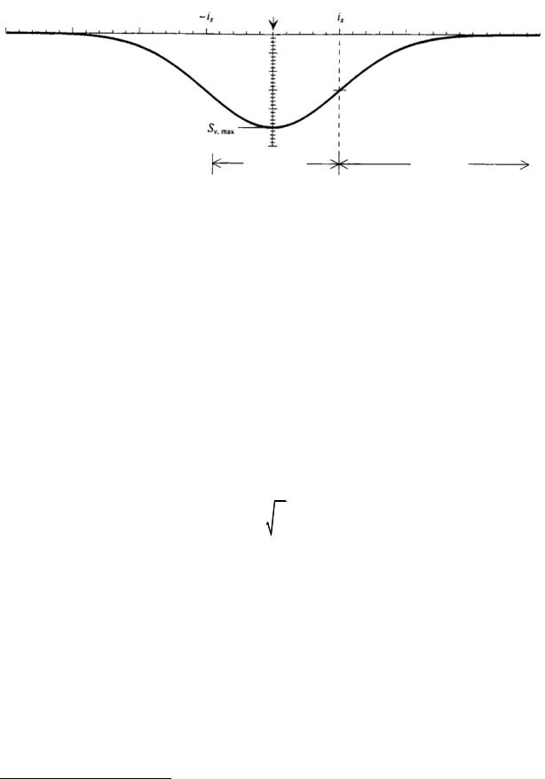
Fig. 4. Shape of a trough of heaving of the Earth’s surface caused by moving of the interstate tunnel complex
A typical character of a trough of heaving of the Earth’s surface in the transverse direction is shown in Fig. 5. A maximum inclination of a trough of heaving is at the bend point that is at the distance ix from the central transverse axis of the tunnel. The bend point separates the curve area from the bend area [10, 14].
The area of the zone restricted by the Gaussian function is defiend to be one. Thus the area determined by a curved line of heaving (3) presented above is calculated using the formula:
|
|
Vs S dx , |
(4) |
where Vs is the volume of a trough of heaving per a unit of the length of the tunnel.
86
Issue № 1 (37), 2018 |
ISSN 2542-0526 |
Axis of the tunnel
Heaving
Transverse direction
Bend point
Bend Curve
Fig. 5. Heaving of the Earth’s surface in the transverse direction during the use of the interstate tunnel complex
In soils that are weakly water-resistant a displacement of soil particles towards the tunnel lining is not accompanied by drainage. In other words, a gap between the tunnel lining and boundary of the developed vacuum is completely filled with the soil. Therefore a volume of the surface trough of heaving is equal to that of the soil removed apart from the volume taken up by the tunnel. It is generally defiend as a ratio of this extra (lost) volume to that of the tunnel (per a unit of its length):
V |
V |
D2 |
, |
(5) |
sp |
L |
4 |
|
|
|
|
|
|
where VL is the loss of a volume; D is the external diameter of the tunnel.
In practice the expression (5) is used in percentage. Considering the dependencies (4) and (5), the expression (3) can be transformed to be as follows:
|
V D2 |
|
x2 |
|
||
Sv (x) |
2i2 |
|
(6) |
|||
2 |
L |
e |
x . |
|||
|
4ix |
|
|
|
|
|
For this diameter of the tunnel D the shape and value of a transverse curved line of heaving depends only on the loss of the volume of the soil VL and width of a trough ix. These two critical parameters will be described in more detail below.
“Loss of volume” of the soil VL is the difference of a chosen soil and theoretical volume of a tunnel taken up by a unit of the length of a tunnel.
During construction of tunnels using shielding, the deformation of the soil surface is affected by the following factors:
––selection and release of a rock in a bottom1;
––movement of shields even with a small attack angle;
1 Note: selection is choosing a large volume of a rock compared to that of a tunnel; release is an excessive amount of a grouting mortar or a rock behind the tunnel facing.
87

Russian Journal of Building Construction and Architecture
––an increased construction gap between the lining and soil massive;
––compliance of the lining;
––deformations of shields and their vibrations.
All of these factors determine the value of a “lost volume” that heaving of a daily surface will largely depend on.
The modern technology of tunneling allows movements of soil to be restricted so that the damage that might be incurred by equipment on and under the ground is minimum. Nevertheless it is not possible to completely avoid the impact of shielded tunnelling on the environment.
In order to evaluate the width of a hole on the soil surface it is convenient to use the parameter of a trough of heaving ix. In a transverse section of a curved line of heaving this distance from the bend point (i.e. points of maximum inclination) to the axis of the tunnel. O`Reilly and New [15, 18] conducted a large number of measurements using the curved lines during construction of tunnels in clay rock. As a result of processing the experimental data, we obtained the following linear dependence of the parameter of the width of a trough ix on the depth of tunnelling z0:
ix 0.43z0 1.1. |
(7) |
Based on the analysis of the experimental data obtained by the authors of [15, 18], it was concluded that for clay rock in many cases the coefficient К that determines the bend point can be determined using the formula K = 0.5. At the same time they pointed out that his value might range between 0.4—0.7 for a rigid and soft clay respectively. As seen from Fig. 6, a simple linear function describes a dependence obtained experimentally in field conditions quite well. Nevertheless to make it more convenient to use for accurate engineering calculations, the authors [15, 18] made the equation (7) more simple by making it:
(8) Later on L. M. Lake, W. J. Rankin and J. Hawley [16] proved the value K = 0.5 based on the large amount of data obtained in field conditions. Therefore a simple dependence is obtained:
ix 0.5z0 . |
(9) |
Apart from the field measurements, R. J. Mair, M. J. Gunn and M. P. O’Reilly [17] conducted tests using a centrifuge. The results of the tests showed that the value K = 0.5 does not depend on the rigidity of a tunnel structure. The authors [17] concluded that the value K does not depend on a tunneling method.
88

Issue № 1 (37), 2018 |
ISSN 2542-0526 |
ix, m
Fig. 6. Dependence of the distances from the bend point ix to the surface of heaving to the axis of the tunnel to the depth of the tunnel z0
For a comparative analysis of the obtained result using the finite element method, heaving of the Earth’s surface was calculated during the use of an interstate tunnel powered complex using the above analytical method.
The diameter of the axis of the shell of the tunnel lining is D = 5.8 m = 5800 mm. The depth of the tunneling axis is z0 = 22.7 m =22700 mm.
The parameter ix = 11350 mm.
The volume of a trough of heaving per a unit of the length of the tunnel is
|
|
|
2 3.14 11350 S ,max 28443 S ,max (mm2). (10) |
Vs |
S dx |
2 ix S ,max |
|
|
|
|
|
The volume of a “lost soil” per a unit of the length of the tunnel is accepted to be 0.015
(1.5 %) of the tunnel volume VL = 0.015. |
|
|
|||
The volume of a “lost soil” per a unit of the length of the tunnel is |
|
||||
V |
V D2 |
0.015 3.14 58002 |
396111 mm2. |
(11) |
|
sp |
L |
4 |
4 |
|
|
|
|
|
|
||
Equalling the volume of a trough of heaving to that of a “lost soil” is |
|
||||
|
|
|
28443 Sv,max 396111, |
(12) |
|
we obtain a maximum size of heaving of the surface:
Sv,max |
396111 |
13.9 mm . |
(13) |
|
28443 |
|
|
As a result of the analytical calculation, a maximum heaving of the Earth’s surface over the tunnel axis was
Sv,max 13.9 mm . |
(14) |
89

Russian Journal of Building Construction and Architecture
A divergence is 6.4 % from the value of heaving obtained using MSC PATRAN — NASTRAN. This indicates that the results of numerical and analytical calculations are in agreement and the resulting finite element model performs well.
Conclusions. 1. The authors have developed a method to allow one to determine heaving of the Earth’s surface during the movement of an interstate tunnel powered complex using the finite element method due to the use of contact elements GAP.
2.In order to test the developed method, the calculation of heaving of the Earth’s surface was performed for the movement of an interstate tunnel powered complex using an analytical method.
3.The results of the calculations obtained using numerical and analytical methods are in good agreement with each other both qualitatively and quantitatively, which indicates that the designed model is valid.
References
1.Aleksandrov A. V., Potapov V. D. Osnovy teorii uprugosti i plastichnosti [Fundamentals of the theory of elasticity and plasticity]. Moscow, Vysshaya shkola Publ., 1990. 400 p.
2.Gabbasov R. F. K raschetu gibkikh trub na sovmestnoe deistvie vneshnei nagruzki i vnutrennego davleniya s uchetom otpora grunta [To the calculation of flexible pipes for the joint action of external loads and internal pressure, given the resistance of the soil]. Gidrotekhnicheskoe stroitel'stvo, 1970, no. 10, pp. 17—19.
3.Klein G. K. Raschet podzemnykh truboprovodov [Calculation of underground pipelines]. Moscow, Izdatel'stvo literatury po stroitel'stvu, 1969. 240 p.
4.Kositsyn S. B., Dolotkazin D. B. Raschet sterzhnevykh sistem, vzaimodeistvuyushchikh s uprugim osnovaniem, metodom konechnykh elementov s ispol'zovaniem programmnogo kompleksa MSC/NASTRAN FOR WINDOWS [Calculation of rod systems interacting with an elastic Foundation, finite element method using the software complex MSC/NASTRAN FOR WINDOWS]. Moscow, MIIT Publ., 2004. 116 p.
5.Kositsyn S. B., Chan Suan Lin'. Chislennyi analiz napryazhenno-deformirovannogo sostoyaniya ortogonal'no peresekayushchikhsya tsilindricheskikh obolochek bez ucheta i s uchetom ikh odnostoronnego vzaimodeistviya s okruzhayushchim massivom grunta [Numerical analysis of stress-strain state of orthogonally intersecting cylindrical shells without taking into account and taking into account their unilateral interaction with the surrounding soil mass]. International Journal for Computational Civil and Structural Engineering, 2014, vol. 10, iss. 1, pp. 72—78.
6.Leont'ev N. N. [A practical method of calculation of thin-walled cylindrical pipe on an elastic Foundation]. Trudy Moskovskogo inzhenerno-stroitel'nogo institute [Proc. of the Moscow Institute of civil engineering], 1957, no. 27, pp. 47—69.
7.Prevo R. Raschet na prochnost' truboprovodov, zalozhennykh v grunt [Calculation of the strength of pipelines laid in the ground]. Moscow, Stroiizdat Publ., 1964. 123 p.
8.Shagivaleev K. F. Raschet zamknutoi tsilindricheskoi obolochki, zapolnennoi sypuchim materialom, na radial'nuyu nagruzku [The calculation of a closed cylindrical shell filled with loose material, radial load]. Izvestiya vuzov. Stroitel'stvo, 2003, no. 2, pp. 20—23.
90