

2918
.pdfIssue № 1 (37), 2018 |
ISSN 2542-0526 |
3.Kuritsyn B. N., Osipova N. N., Ivanova E. V. Detsentralizovannye sistemy snabzheniya szhizhennym gazom ot individual'nykh ballonnykh ustanovok [Decentralized system to supply liquefied gas from the individual cylinder installations]. Stroitel'naya inzheneriya, 2006, no. 6, pp. 47—52.
4.Kuritsyn B. N., Osipova N. N., Maksimov S. A. Osobennosti ekspluatatsii regulyatorov davleniya rezervuarnykh ustanovok szhizhennogo uglevodorodnogo gaza [Features of operation of pressure regulators of tank installations of liquefied petroleum gas]. Vestnik VolgGASU. Stroitel'stvo i arkhitektura, 2013, no. 30 (49), pp. 216—
5.Kuritsyn, B. N., Nedlin M. S., Ivanova E. V. Povyshenie nadezhnosti gazosnabzheniya ot ballonnykh ustanovok szhizhennogo gaza [Increase of reliability of gas supply from balloon installations of liquefied gas]. Gaz Rossii, 2005, no. 1, pp. 30—31.
6.Kuritsyn B. N., Osipova N. N., Maksimov S. A. Razrabotka i obosnovanie tekhnicheskikh reshenii po preduprezhdeniyu gidratooobrazovaniya v sistemakh rezervuarnogo snabzheniya szhizhennym gazom [Development and justification of technical solutions for prevention of hydrate formation in systems of tank supply with liquefied gas]. Privolzhskii nauchnyi zhurnal, 2013, no. 1 (25), pp. 73—80.
7.Makogon Yu. F., Sarkis'yants G. A. Preduprezhdenie obrazovaniya gidratov pri dobyche i transporte gaza
[The prevention of formation of hydrates during production and transport of gas]. Moscow, Nedra Publ., 1966.
186p.
8.Mikheev M. A., Mikheeva I. M. Osnovy teploperedachi [Basics of heat transfer]. Moscow, Energiya Publ., 1977. 344 p.
9.Nikitin N. I., Kuritsyn B. N., Usachev A. P. [Condensation and measures to prevent it in the distribution pipelines liquefied natural gas]. Trudy Giproniigaz «Ispol'zovanie gaza v narodnom khozyaistve» [Proc. GIPRONIIGAZ "Use of gas in the national economy»]. Saratov, Kommunist Publ., 1971, vol. 2, pp. 20—23.
10.Nikitin N. I., Krylov E. V. [Analysis of the throttling processes of liquefied gas vapors in the pressure regulator]. Trudy Giproniigaz «Ispol'zovanie gaza v narodnom khozyaistve» [Proc. GIPRONIIGAZ "Use of gas in the national economy»]. Saratov, Kommunist Publ., 1974, vol. 11, pp. 331—337.
11.Osipova N. N. Issledovanie protsessa gidratoobrazovaniya pri redutsirovanii vlazhnogo gaza [The study of the process of hydrate formation when wet gas reduction]. Privolzhskii nauchnyi zhurnal, 2012, no. 3 (23), pp. 112—117.
12.Osipova N. N. [The study of heat transfer between the ground and the steam phase of the liquefied gas in the underground tank]. Trudy «Energosberezhenie i effektivnost' sistem teplogazosnabzheniya i ventilyatsii» [Proc. «Energy saving and efficiency of heat and gas supply and ventilation systems»]. Saratov, SGTU Publ., 2000.
180p.
13.Osipova N. N. Sistemy avtonomnogo gazosnabzheniya naselennykh punktov [Systems of Autonomous gas supply to settlements]. Vestnik VolgGASU. Stroitel'stvo i arkhitektura, 2011, no. 22, pp. 115—120.
14.Preobrazhenskii N. I. Szhizhennye uglevodorodnye gazy [Liquefied petroleum gas]. Leningrad, Nedra Publ., 1975. 279 p.
15.Spektor N. Yu., Sarkisov A. S. Analiz gazifikatsii Rossiiskoi Federatsii [Analysis of gasification of the Russian Federation]. Problemy ekonomiki i upravleniya neftegazovym kompleksom, 2015, no. 5, pp. 25—29.
16.Osipova N. N. et al. STO 03321549-021-2012. Standart organizatsii «Preduprezhdenie obrazovaniya ledyanykh i gidratnykh probok v sistemakh rezervuarnogo snabzheniya szhizhennym gazom» [STO 03321549-021-
51

Russian Journal of Building Construction and Architecture
2012. Standard of the organization «Prevention of formation of ice and hydrate plugs in systems of tank supply with liquefied gas»]. Saratov, OAO «Giproniigaz» Publ., 2012. 20 c.
17.Tilicheev M. D., Iogansen A. V. Plotnost' uglevodorodov v zavisimosti ot temperatury [The density of hydrocarbons, depending on the temperature]. Moscow, Gostoptekhizdat Publ., 1957, vol. 6. 736 p.
18.Usachev A. P., Kuritsyn B. N. [The heat transfer coefficient of ground of the evaporator of the liquefied gas at a constant vapor selection]. Trudy «Raspredelenie i szhiganie gaza» [Proc. «Distribution and combustion of gas»]. Saratov, SPI Publ., 1977, pp. 73—76.
19.Shamin O. B. [The steam capacity of the underground reservoir units of liquefied natural gas with vertical placement of reservoirs]. Trudy «Sovershenstvovanie arkhitekturnykh reshenii, stroitel'nykh konstruktsii, tekhnologii i organizatsii stroitel'stva» [Proc. «Improvement of architectural solutions, building structures, technologies and organization of construction»]. Saratov, SGTU Publ., 1997, pp. 185—189.
20.Yarygin Yu. N. Avtonomnaya gazifikatsiya: nauchnoe i proektnoe obespechenie [Independent gasification: scientific and design support]. Gaz Rossii, 2010, no. 3, pp. 17—19.
21.BP Statistical Review of World Energy: statistical Review, June 2011. London, Beyond petroleum, 2011.
49р.
22.Cristescu T., Avram L., Stoica M. E. Possible thermal processes involved in the storage of liquefied petroleum gas. Termoтеhnicа, 2013, no. 2, pp. 63—66.
23.Giavarini C., Hester K. Hydrates Seen as a Problem for the Oil and Gas Industry. London, Springer, 2011, pp. 97—116.
24.Zakana Zainal, Mat Hanapi, Jurun Radzuan, Mustafa Muhammad Azeman. Faizal Heat and mass transfer studies in uquefdzd petroleum gas storage operations. Gas Fakulri Kejuruteraau Kimia & Kejuruteraau Surnber Asli Universiti Teknologi Malaysia, 2006. 749 р.
25.Hunter B., Zhixiong G. Numerical smearing, ray effect, and angular false scattering in radiation transfer computation. International Journal of Heat and Mass Transfer, 2015, vol. 81, pp. 63—74.
26.Osipova N. N., Grishin B. M., Rodionov Yu. V., Tarakanov O. V., Greisukh G. I. Justification of operating conditions for gas supply systems based on cylinder units of liquefied hydrocarbon gas. Journal of Engineering and Applied Sciences, 2016, vol. 11, no. 12, pp. 2723—2728.
27.Varaminian F., Varaminian F., Izadpanah A. A. Modeling of methane and propane hydrate formation kinetics based on chemical affinity. Proceedings of the 7th International Conference on Gas Hydrates (ICGH 2011), July 17—21. Edinburgh, Scotland, United Kingdom, 2011. 8 p.
28.Yuguang Ye., Changling Liu. Natural Gas Hydrates: Experimental Techniques and Their Applications. London, Springer Science & Business Media, 2013. 404 p.
52

Issue № 1 (37), 2018 |
ISSN 2542-0526 |
UDC 621.6.036
A. L. Shuraits1, A. V. Rulev2, E. Yu. Usacheva3
CHOICE OF MIXTURES OF AGENTS IN HEAT PUMPS
FOR HEATING AND COOLING MEDIA WITH LIMITED CAPACITY
JSC «Giproniigaz»
Russia, Saratov, e-mail: shuraits@niigaz.ru 1D. Sc. in Engineering, Prof., General Director
Saratov State Technical University Named after Y. A. Gagarin Russia, Saratov, e-mail: usachev-ap@mail.ru
2D. Sc. in Engineering, Prof. of the Dept. of Heat, Ventilation, Water Supply and Applied Fluid Dynamics 3PhD student of the Dept. of Heat, Ventilation, Water Supply and Applied Fluid Dynamics
Statement of the problem. The goal of the study is to make the selection of the components of a zeotrope mix and concentrations of its low-boiling component with a lower boiling point, which is the minimum value of the difference between its average temperature in the evaporator and condenser of heat pumps used for heating and cooling environments with limited thermal capacity.
Results. This paper provides a description of the method and methodical provisions for determining the minimum magnitude of the difference of average temperatures of a zeotrope mix in the condenser and the evaporator, which is achieved by the selection of its components and the values of the concentration of the low-boiling component.
Conclusions. The proposed method and assumptions on achieving the minimum value of the difference of the average temperatures of a zeotrope mix in the condenser and evaporator by choosing each of the two similar ones based on the physical properties of its components and the values of the concentration of the low-boiling component on the basis of the dependence of the saturation temperature of the mixture in the evaporator and condenser of the heat pump on the relative amount of its vaporized liquid phase. It was shown that there is a significant influence of the temperatures of the heated and cooled environments with limited heat capacity on the selection of the components of a zeotrope mix and the value of its low-boiling component, the one that produces the minimum value of the difference of average temperatures of condensation and boiling, and as a result, the maximum energy efficiency.
Keywords: choice, mix, operating agent, compressor, heat pump, system heat gas provision and ventilations, heating, cooling, medium with limited heat capacity.
Introduction. During the use of renewable thermal sources that have a limited volumetric capacity, e.g., the air whose temperature considerably changes during cooling in the evapora-
© Shuraits А. L., Rulev А. V., Usacheva E. Yu., 2018
53

Russian Journal of Building Construction and Architecture
tor and heating in the heat pump condenser, the use of substances with constant boiling and condensation temperatures as working substances is characterized with a reduction in the energy efficiency of its use [5, 13, 21].
Simultaneously implementation of a cycle with variable temperatures of media with a limited heat capacity as well as working substances in the condensers allows the energy efficiency of heat pumps to be improved [1, 2, 19]. The use of working substances consisting of zeotropic mixtures with variable temperatures in the evaporator and condenser of the heat pump has been studied by A. A. Sukhikh, K. S. Generalov, I. A. Akimov [13], V. G. Bukin, Yu. A. Kuzmin [1, 2], М. Kim and other foreign authors [16—18], L. А. Оgurechnikov, N. N. Mezentseva [8, 9] as well as other research institutions of Moscow Power Engineering Institute, Kutateladze Institute of Thermal Physics (Siberian Department of the Russian Academy of Sciences), Astrakhan State Technical University, etc. In [9] it is concluded that the condensation and boiling temperatures in the evaporator of the heat pump have a significant effect on the composition of the zeotropic mixtures of temperatures. The former also depend on changing temperatures of heated and cooled media with a limited heat capacity.
However, to the best of our knowledge, the problems of choosing the best combinations of mixtures of working substances and their composition in compression heat pumps of systems of heat and gas supply and ventilation for heating and cooling of media with a limited heat capacity providing a maximum energy efficiency.
1. Justification of brands of working substances for use as components of the zeotropic mix in heat pumps. Working substances used as components of the zeotropic mixture in heat pumps should not damage the atmospheric ozone layer [7] and have any negative effect on climate change [3], be fire-safe, easy to use, cost-efficient, have no impact on human health, have variable boiling and condensation temperatures that are most suitable for heating and cooling of media with a limited heat capacity in systems of heat and gas supply and ventilation. Presently there are no working substances that perfectly comply with all of the requirements. E.g., freons R11, R12, which used to be common and could be used as components of the zeotropic mixture in systems of heat and gas supply and ventilation, have a negative impact on the atmospheric ozone and heat-reflecting layer. Therefore the choice of the components for the zeotropic mixture is individual for heating and cooling of such media as water, air and natural gas in systems of heat and gas supply and ventilation given all the positive and negative factors of their influence.
According to the analysis, zeotropic mixtures that consist of R22/R142b, R32/R134а, R32/R152а or saturated hydrocarbons R290/600 (propane and butane), R600а/R601 (isobu-
54
Issue № 1 (37), 2018 |
ISSN 2542-0526 |
tene and n-pentane), R290/R601а (propane and isopentane), R600а/R601b (isobutene and new pentane). E.g., according to the activity of the depletion of the Earth’s ozone layer, saturated hydrocarbons are considered completely safe. These gases do not cause the greenhouse effect, have no negative impact on climate change, human body, they are extracted immediately from natural gas and are considerably more cost-efficient that other working substances. Mixtures of R22/R142b, R32/R134а, R32/R152а are characterized with low ozone-depletion activity and cause no greenhouse effect.
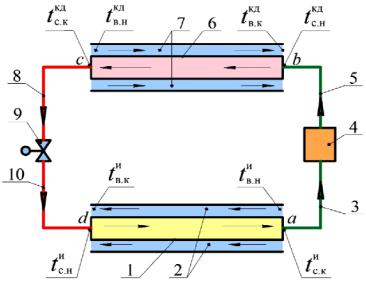
A considerable drawback of zeotropic mixtures is a reduction in the coefficient of heat emission in “the internal surface of heat exchange pipes – working substance” system of the evaporator and condenser of the heat pump (Fig. 1) due to a reduction in the centers of vapor formation and a drop in the diameter of the bubble that breaks away compared to each of the components of the mixture [4].
Denotations in the zeotropic mixture: а––b are pressing of the vapor phase in the compressor 4; b––c is condensation of the vapor phase in the condenser 6; c––d is a reduction in the temperature of the saturated liquid phase in the controller 9; d––a is evaporation of the saturated liquid phase in the evaporator 1.
tскд.н , tскд.к is the initial and final temperature of condensation of the vapor phase of the zeotropic mixture in the condenser, оС;
tси.н , tси.к is the initial and final boiling temperature of the liquid phase of the mixture in the evaporator, оС
Fig. 1. Scheme of the heat pump operating using zeotropic mixtures with a counterflow of the mixture and a medium with a limited heat capacity in the evaporator and condenser:
1 is a counterflow pipe evaporator; 2 is a space between the pipes in the evaporator 1;
3 is a pipeline of the vapor phase of the zeotropic mixture for joining with the output of the evaporator 1; 4 is a compressor; 5 is a pipeline of the vapor phase of the zeotropic mixture for joining with the output of the
compressor 4; 6 is a counterflow pipe condenser; 7 is a space between the pipes in the condenser 6;
8 is a pipeline of the liquid phase of the zeotropic mixture for joining with the output of the counterflow pipe condenser 6; 9 is a controller for reducing the temperature of the saturared liquid phase of the zeotropic mixture; 10 is a pipeline of the liquid phase of the zeotropic mixture for joining the controller 9
with the output of the pipe evaporator 1
55

Russian Journal of Building Construction and Architecture
In addition, during heating and cooling of media with a limited heat capacity such as air and other gaseous substances it is of not much importance. The calculations performed according to [4, 6, 15] show that a reduction in the total coefficient of heat emission is not over 5.5 %. This is due to the fact that the main proportion of the coefficient of heat transfer is in the heat emission coefficient in “the outer surface of the ribbed heat exchange pipes – medium with a limited heat capacity” system that is characterized with a lower forced flow compared to the zeotropic mixture. This reduction in the intensity of heat exchange and thus an increase in capital investments in heat exchange surfaces of the evaporator and condenser in this case is much lower compared to that of operational expenses due to an increase in the coefficient of transformation of the compression heat pump.
A drawback of saturated hydrocarbons as they are used as the components of zeotropic mixtures is their flammability. Therefore industrial heat pumps set up in the premises should be fitted with fire detectors. Simultaneously during the use as a drive of a compressor of a gas engine that is most suitable for heating media with a limited heat capacity of systems of gas and heat supply and ventilation, setting up a fire detector is essential as it is based on the fire safety regulations for gas supply structures according to SP 42-101-2003 and Federal Standards and Regulations (FNiP) for industrial safety “Safety Regulations of Gas Distribution Gas Consumption Networks” (Act by the Federal Environmental, Engineering & Nuclear Supervision Agency from November 11, 2013, no. 542). In addition, for modern heat pumps that are not much filled even for leaking of the entire working substance its concentration in a premises with the geometric volume of 15 m3 is nine and more times lower than the lower concentration limit of flammability of the mixture R600а and R601 that is со 1.7—1.35 % [10, 12]. Moreover the compression and evaporation equipment and all the elements in bivalent systems filled with a working substance are commonly outdoors.
Considering the total combination of advantages and disadvantages, presently over 35 % of refrigerators in households of Europe and Asia run on isobutane R600a, propane R290, mixtures of saturated hydrocarbons as they are more commonly used, cost-efficiency and economic sustainability.
2. Developing methods and ways of achieving a minimum difference of average temperatures of condensation and boiling of the zeotropic mixture in the condenser and evaporator of the heat pump. The main drawback of existing heat pumps using pure substances for heating and cooling of media with a limited heat capacity as working substances are large differences of the temperatures between:
56
Issue № 1 (37), 2018 |
ISSN 2542-0526 |
––a working substance with a constant boiling temperature in the evaporator and a medium with a limited heat capacity that causes a considerable reduction in the parameter in a space between the pipes;
––a working substance with a constant condensation temperature in the condenser and a medium with a limited heat capacity that causes a considerable reduction in the parameter in a space between the pipes in the condenser;
––a working substance in the evaporator and condenser and thus a low energy efficiency of the heat pump.
These large differences are due to the following. The temperature of a working substance being used that consists of one substance during boiling in the evaporator and a transition from the vapor into the liquid state in the condenser is constant. Additionally for more complete heat extraction the temperature of a medium with a limited heat capacity should go down and conversely, in the condenser it goes up. This causes an increase in the average difference of the temperatures between a working substance and a medium with a limited heat capacity in the evaporator and condenser of the heat pump compared to when the temperatures of a working substance and a medium with a limited heat capacity and thus a difference of their temperatures will be constant throughout the entire process.
The use of working substances consisting of zeotropic mixtures with variable temperatures in the evaporator and condenser allow a considerable reduction in the difference between the temperatures in the evaporator and condenser of the heat pump.
The objective of the paper is to decrease the difference between the temperatures of a working substance of a zeotropic mixture in the evaporator and condenser of the heat pump down to a minimal value that corresponds with its maximum energy efficiency.
The heat pump that implements the cycle with variable temperatures of the zeotripic hydrocarbon mixture used as a working substance and media with a limited heat capacity used as sources of heat and drain with counterdirections of their flow (see Fig. 1) operates in the following way. In the counterflow pipe evaporator 1 (Fig. 1) the zeotropic mixture consisting of two components with similar physical properties (e.g., isobutene and pentane (R600а/R601), propane and butane R290/R600, propane and isopentane R290/R601а) transforms from the liquid into the
vapor state at a variable temperature from the initial tси.н at the input to the final tси.к at the ouput of the evaporator 1 due to heat provided from a heat source with a limited heat capacity from a space between the pipes 2. Change in the temperature of a two-component zeotropic mixture in the counterflow pipe evaporator 1 is shown in the “temperature –– area of a heat
57
Russian Journal of Building Construction and Architecture
exchanger” graph (Fig. 2). As a result of cooling, the heat source with a limited heat capacity reduces its temperature from the initial tви.н at the input to the final tви.к at the output from a space between the pipes 2 of the evaporator (Fig. 2).
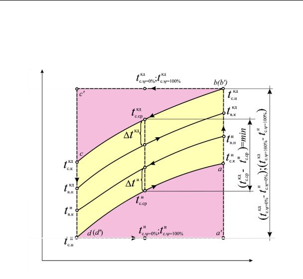
Temperature, t °C
Area, F, m2
Fig. 2. Graph of changes in the temperatures of the zeotropic mixture and medium with a limited heat capacity that allows a minimum difference between the average temperatures to be evaluated in the counterflow evaporator and condenser of the heat pump:
tcкд.ψ=0,0% , tcкд.ψ=100% are the constant temperatures of condensation of the vapor phase of pure substances in the condenser, оС; tcи.ψ=0,0% , tcи.ψ=100% are the constant temperatures of boiling of the liquid phase of pure substances in the evaporator, оС; tви.н, tви.к are the initial and final temperature of a medium with a limited heat capacity, e.g., the air in a space between the pipes in the evaporator, оС; tвкд.к, tвкд.н are the final and initial temperature of a medium with a limited heat capacity, e.g., the air in the condenser, оС; tкд, tи are the temperature pressures between heat exchanging flows respectively in the counterflow condenser and evaporator, оС; tскд.ср , tси.ср are the average temperatures of condensation and boiling of the zeotropic mixture in the condenser and evaporator respectively, оС. Denotations of the processes in pure substances: a ––b is compression of the vapor phase in the compressor 4; b ––c is condensation of the vapor phase in the condenser 6; c ––d are reduction in the temperature of the saturated liquid phase in the controller 9; d ––a is evaporation of the saturated liquid phase in the evaporator 1
58
Issue № 1 (37), 2018 |
ISSN 2542-0526 |
The two-component zeotropic mixture in the counterflow pipe evaporator 1 and a heat source with a limited heat capacity in the space between the pipes 2 move in opposite directions at an average difference between the zeotropic mixture and the heat source with a limited heat capacity that is t и and constant at any point of the evaporator (the cycle a-b-c-d-a, Fig. 2).
A saturated vapor phase forming in the counterflow pipe evaporator 1 from the zeotropic mixture through the pipeline 3 with the temperature tси.к are directed into the compressor 4. Here it should be noted that for the sake of simplicity the scheme in Fig. 1 does not include a regenerative heat exchanger recommended in [2, 13, 19] for overheating of the vapor phase at the output of the evaporator 2 over tси.к due to the heat of the liquid phase at the output of the condenser 6 and thus preventing hydraulic shocks in the compressor 4 owing to the drops that were not completely evaporated in the evaporator 1. However the fact that the regenerative heat exchanger is not included into the scheme in Fig. 1 has almost no effect on the objective of the study, i.e. a selection of the components and composition of the zeotropic mixture when a minimum difference between the condensation and boiling temperatures of the mixture is achieved. In the compressor 4 the vapor phase is compressed up to the pressure Ркд when its temperature becomes equal to the initial value tскд.н . From the compressor 4 the saturated liquid phase from the zeotropic mixture is directed through the pipeline 5 into the counterflow pipe condenser 6. In the counterflow pipe condenser 6 the zeotropic mixture transforms from the vapor to the liquid state at a variable temperature from the initial at the input tскд.н to the final tскд.к at the output (Fig. 2) due to the emission of the heat condensation of the zeotropic mixture through the walls of the counterflow pipe condenser 6 to a heated medium with a limited heat capacity flowing in a space between the pipes 7. As a result, a medium with a limited heat capacity результате is heated and increases its temperature from the initial tвнкд at the input to the final tвккд at the output from a space between the pipes 7 of the condenser (Fig. 2). The condensing zeotropic mixture in the counterflow pipe condenser 6 and a heated medium with a limited heat capacity flowing in a space between the pipes 7 move in the opposite directions at an average difference of the temperatures between the zeotropic mixture and a heat source with a limited heat capacity that is t кд , which is constant at any point of the condenser 6 (the cycle a-b-c-d-a, Fig. 2).
The saturated liquid phase formed in the counterflow pipe condenser 6 from the zeotropic mixture through the pipeline 8 is directed into the controller 9 where its pressure is reduced to the value that corresponds with the temperature of the start of boiling tси.н that is necessary for
59

Russian Journal of Building Construction and Architecture
cooling of a medium with a limited heat capacity. Then the saturated liquid phase of the zeotropic mixture with the temperature of the start of boiling tси.н is directed through the pipeline 10 into the counterflow pipe evaporator 1. In the counterflow pipe evaporator 1 the saturated liquid phase of the zeotropic mixture is saturated again and the cycle is repeated in the sequence similarly described above.
The novelty of the suggested method is that each of the two components of the zeotropic mixture similar in their physical properties as well as the value of the molar concentration of a lowboiling component of the mixture ψi is selected so that a minimum difference between the average temperatures of condensation and boiling by means of choosing based on the expression
tскд.ср tси.ср min , |
(1) |
where ψi is the i-th value of the molar concentration of a low-boiling component in the zeotropic mixture from two components with similar physical properties at ψi = ψн,…ψх,...ψy,…ψk, mole %; tскд.ср , tси.ср are the average temperatures of condensation and boiling of the zeotropic
mixture respectively in the counterflow condenser and evaporator, оС.
According to [5], a maximum energy efficiency, i.e. a maximum coefficient of transformation for the cycles of heat pumps with a variable temperature is achieved at a minimum difference between the average temperatures of the zeotropic mixture in the condenser and evaporator.
If for the counterflow condenser and evaporator the difference between the temperatures
tкд |
tи |
is larger than |
tкд |
tи |
|
, the formula (1) can be written as follows [6]: |
|
|||||
с.н |
с.к |
|
с.к |
с.н |
|
|
|
|
|
|
|
|
|
|
|
|
|
tскд.ср tси.ср |
|
tскд.н tси.к tскд.к tси.н |
min . |
(2) |
|||
|
|
|
|
|
|
tскд.н tси.к |
||||||
|
|
|
|
|
|
|
|
ln |
|
|
||
|
|
|
|
|
|
|
|
tскд.к tси.н |
|
|
|
|
If for the counterflow condenser and evaporator the difference between the temperatures
tкд |
tи |
is larger than |
tкд |
tи |
|
, the formula (1) can be written as follows [6]: |
|
||||
с.к |
с.н |
|
с.н |
с.к |
|
|
|
|
|
|
|
|
|
|
|
|
tскд.ср tси.ср |
tскд.к tси.н tскд.н tси.к |
min . |
(3) |
|||
|
|
|
|
|
|
tскд.к tси.н |
|||||
|
|
|
|
|
|
|
ln |
|
|
||
|
|
|
|
|
|
|
tскд.н tси.к |
|
|
|
|
The values of the initia, current and final temperatures of condensation t in the condenser in the range tскд.н tскд.к as well as initial, current and final temperatures of boiling t in the evaporator tси.н tси.к depending on the relative quality (dryness) Х of the zeotropic mixture that is boiled or condensed at a specified molar concentration of a low-boiling component ψi are de-
60