

2918
.pdfIssue № 1 (37), 2018 |
ISSN 2542-0526 |
According to the obtained value Еu using the formula (8), a movement of a flexible thread f under the force F can be made more accurate.
Let us use the results of the calculation of the rope bar from [5] as an example. With the area of the section А = 7.05 сm2 and standardized resistance of the rope Rsn = 1300 МPа the limited effort in the rope is Nu = 916.5 kN. Considering N0 = 0 and F = 222 kN using the formula (8) Еu = 44600 МPа was obtained. This corresponds with the coefficient of plasticity (the ratio of the complete bend to the elastic one)
K pl 180000 / 44600 4 K pl
(with the elasticity modulus Е = 180000 МPа). A limited value of the elasticity coefficient is given by [1]:
|
|
pl s2 E / Rsd 0.002E 4.7, |
|
K |
(9) |
||
where s2 = 0.05 is a maximum acceptable an even relative increase in the length; Rsd is the resistance of the rope under a dynamic load: Rsd = 1.2·1300 = 1560 МPа.
According to the formula (6) at Е = Еu a deflection of stretching f = 72 cm was determined. Note that the use of the initial stretching N0 of the rope without an increase in the area of the section has almost no influence on the value of the deflection of stretching due to a reduction in the conditional elasticity modulus. E.g., at N0 = 300 kN Еu = 40000 МPа was obtained as well as Kpl = 4.5 andf = 72 сm. An increase in the initial stretching up to N0 = 500 kN was not acceptable as Еu = 31800 МPа and Kpl = 5.7 > 4.7.
3. A dynamic calculation of the flexible thread. A dynamic effect during a sudden failure of the elements of construction schemes is essential due to the complexity of the task [9, 10]. For a dynamic calculation of the flexible thread a model that is described in [12] is used. A calculation scheme of stretching is considered as a thread with one end fixed and the other one stretched by a conditional counterbalance through a block (a vertical part of the thread is considered unstretchable) (Fig. 2).
Fig. 2. Calculation scheme of the thread under a dynamic impact
11

Russian Journal of Building Construction and Architecture
It is assumed that as a result of a static load F the corresponding mass М is moved at the distance f0 and there is an effort N0 in the stretching. Due to a momentary application of the mass М there is an oscillation of the thread with the movements u and the mass of the counterbalance М0 that generates the stretching N during the oscillations of the thread is increased by z.
In order to solve the task, differential equations of the movement of a material point are used as (10) where y is the acceleration of the point towards the axis γ; Yi are the projections of the
forces applied to the point onto the axis γ.
The masses М0 and М are obtained by dividing the forces N and F into the free fall acceleration g.
Due to a small angle α let us assume that sin α ≈ tg α = 2f/l and the equations (10) are
N0 M0 z N; |
, |
|
|
(F Mf )l / 4 f N, |
|
where f = f0 + u is the deflection caused by the oscillations.
The dependence of the variables z and f is determined using the expression z 2 l / 2 2 f 2 l / 2 2 f02 Z / c ,
(11)
(12)
where Z = N − N0 is a changeable component of stretching of the thread during the oscillations; с = EA/l is a single force of the elastic extension; Z/c is a changeable component of the deformation of the thread.
In the formula (12) the expression in the brackets is transformed by adding the summands f4/l2 and f04/l2 to the radical sums. The acceptable equality of extra summands determined the approximation of the formula (12) as it is more conveniently transformed into
z 2 f 2 f02 / l Z / c . |
(13) |
Considering that in the expression f the component f0 is a constant value, we obtain f" = u". Then the second equation (11) can be written as follows
|
Zu N0u . |
|
Fl / 4 Mu l / 4 (Z N0 ) f0 u Zf0 N0 f0 |
|
|
Considering that Fl/4 = N0f0 (Fig. 2) and neglecting the product Zu, we finally obtain |
|
|
Z Mlu / 4 f0 N0u / f0 . |
|
(14) |
The movement z is written as follows |
|
|
z 2 2 f0u u2 / l Z / c 4 f0u / l Z / c (Ml / 4 f0c)u 4 f0 / l N0 |
/ f0c u. (15) |
|
12
Issue № 1 (37), 2018 |
ISSN 2542-0526 |
Inserting (14) and (15) into the first equation (11), we get a differential equation
|
u4 b1u b2u 0, |
(16) |
where |
b1 N0 4 f02c / l 4 / Ml c / M0 ; |
|
b2 4N0c / MM0l .
Using the solution of the equation (16) in [13], the expressions for the characteristics of the oscillations were obtained:
–– the frequencies:
|
|
b |
2 |
b2 |
4 b ; |
(17) |
1,2 |
|
1 |
|
1 |
2 |
|
–– the amplitude: |
|
|
|
|
|
|
A1 k 22 |
4N0 / Ml / 22 12 ; |
(18) |
||||
–– the calculation parameters: |
|
|
|
|
|
|
h1 Ml 4 f0c ; |
h2 4 f0 |
l N0 f0c ; |
(19) |
|||
–– the maximum acceleration: |
|
|
|
|
|
|
|
|
|
2 |
2 |
h2 ; |
(20) |
zmax 2 1 A1 |
h1 1 |
|||||
–– the maximum stretching of the thread: |
|
|
|
|
|
|
|
|
|
|
|
|
(21) |
|
Zmax M0 zmax . |
|||||
Let us perform a dynamic calculation using the above initial data (with the flight l = 12 m and k = f0 = 0.72 m).
The calculation masses are
M 222 / 9.81 22.6 kN·sec2/m;
M 0 916.5 / 9.81 93.4 kN·sec2/m.
A single force is
с 44600 7.05 /12 10 2620 kN/m. The coefficients of the equation (16) are
b1 4 916.5 4 0.72 2620 /12 / 22.6 12 2620 / 93.4 50.84 sec2; b2 4 916.5 2620 / 22.6 93.4 12 379.12 sec−4.
The frequencies of the oscillations are
|
50.84 / 2 |
50.842 |
/ 4 379.12 |
3.01 sec−1; |
1 |
|
|
|
|
|
50.84 / 2 |
50.842 |
/ 4 379.12 |
6.46 sec−1. |
1 |
|
|
|
|
13
Russian Journal of Building Construction and Architecture
The amplitude is:
А1 0.72 6.462 4 916.5 / 22.6 12 / 6.462 3.012 0.62 m. The calculation parameters are
h1 22.6 12 / 4 0.72 2620 0.036 sec2; h2 4 0.72 /12 916.5 / 0.72 2620 0.726 .
The maximum acceleration is
z 2 3.012 0.62 0.036 3.012 0.726 4.49 m/sec2.
max
The maximum growth in the stretching of the thread during the oscillations is Zmax = 4.49·93.4 = = 420 kN. The dynamic factor is kd = 1 + 420/916.5 = 1.46. This means that it is necessary to strengthen the rope bars almost by 1.5 times.
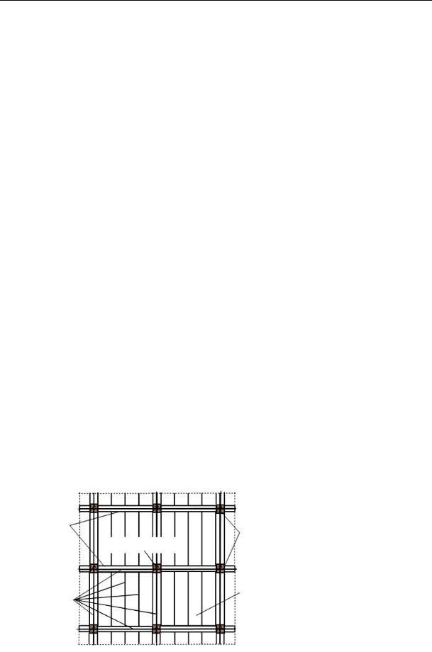
4. A variant of strengthening overlappings of buildings with a braced framing. In order to find a more effective solution of overlappings of buildings with a braced framing, a variant of strengthening using a reinforcement of the type А 500 is employed [5]. Fig. 3 shows a construction scheme of an assembled ferroconcrete overlapping with traditional elements. Reinforcement of cross-bars was calculated based on an operational load. In order to achieve the continuity of the cross-bars, the areas adjoining them with the column are strengthened with a reinforcement equivalent in the strength and rigidity of the longitudinal reinforcement of the cross-bars. The position of the strengthening reinforcement along the height of the cross-bars has no value as the main purpose of the strengthening is to provide the axial rigidity and strength of the belts of the cross-bars for the tensile operation according to the flexible thread scheme. In order to improve the efficiency of the strengthening, a similar reinforcement is provided along the axis of the slabs between the columns as well.
|
Cross-bars |
|
|
|
|
|
|
|
|
|
|
|
|
|
Columns |
|
|
|
|
|
|
|
|
|
|
|
|
|
|
Removed column |
|
|
|
|
Fig. 3. Construction scheme |
|
|
|||||||
|
|
|
|
|
|
|
|
of the reinforced |
|
|
|
|
|
|
overlapping of a building with |
||
|
|
|
|
|
Overlapping |
|||
|
|
|
|
|
|
slabs |
|
a braced framing |
Reinforcement |
|
|
|
|
|
|||
|
|
|
|
|||||
|
|
|
||||||
14

Issue № 1 (37), 2018 |
ISSN 2542-0526 |
As an example let us consider a structure of overlapping with a column grid 6×6 m loaded with an evenly distributed calculated load q = 12 kN/m2 (a standard value of a long-term part of the load g = 7.5 kN/m2). At the operational stage the cross-bars function according to the split beam scheme. A longitudinal operational reinforcement of the cross-bars 4Ø25 А 500 has the area of the section А = 19.625 сm2. The elasticity modulus of the reinforcement Е = 200000 МPа, the standard resistance of the reinforcement is Rsn = 500 МPа.
As the middle column is removed, there is an emergency with an increase in the flight of a structure up to l = 12 m. Even for a long-term part of the load, the elements of overlappings lose their capacity to operate for bending. Thus the calculation scheme of the overlapping over the removed column is considered as a flexible thread (a string). The strengthening of the stretching of the thread Nu = 500·19.625·1.1 = 1079.4 kN is determined considering the dynamic factor kd = 1.1. A thread with the length l = 12 m in each of the directions is laoded in the middle of the flight with the force F = 7.5·6·6/2 = 135 kN.
Considering N0 = 0 according to the formula (6) a value of a conditional elasticity modulus is Еu = 70460 МPа. This corresponds with the plasticity coefficient
Kpl 200000 / 704600 2.84 K pl 10 [5]. According to the formula (6) at Е = Еu a deflection of the stretching is determined
f0 6 1079.42 / 70460 19.625 135 10 0.375 м
(here according to Fig. 1 it is assumed that l = 6 m). According to the obtained data, a dynamic calculation at N0 = 1079.4 kN, f0 = 0.375 m is performed.
The calculation masses are
M 135 / 9.81 13.8 kN·sec2/m;
M 0 1079.4 / 9.81 110 kN·sec2/m.
A single force is
с 70460 19.625 /12 10 11520 kN/m. The coefficients of the equation (15) are
b1 4 1079.4 4 0.375 11520 /12 /13.8 12 11520 /110 165.58 sec2; b2 4 1079.4 11520 /13.8 110 12 2730.5 sec−4.
The frequencies of the oscillations are
|
165.58 / 2 |
165.582 / 4 2730.5 |
4.31 sec−1; |
1 |
|
|
|
|
165.58 / 2 |
165.582 / 4 2730.5 |
12.12 sec−1. |
1 |
|
|
|
15

Russian Journal of Building Construction and Architecture
The amplitude is
А1 0.375 12.122 4 1079.4 /13.8 12 / 12.122 4.312 0.35 m. The calculation parameters are
h1 13.8 12 / 4 0.375 11520 0.0096 sec2;
h2 4 0.375 / 12 1079.4 / 0.375 11520 0.375 . The maximum acceleration is
z 2 4.312 0.35 0.0096 4.312 0.375 0.59 m/sec2.
max
A maximum growth of the stretching of the thread at the oscillations Zmax = 0.59·110 = = 65.3 kN. The dynamic factor is kd = 1 + 65.3/1079.4 = 1.06 < 1.1. This means that extra reinforcement is not necessary.
Conclusions. Therefore if columns in buildings with a braced framing collapse, overlappings have to be reinforced and their tensile load-bearing capacity according to the flexible thread scheme has to be retained.
A momentary failure of a column is accompanied with an oscillation of construction elements and an increase of efforts in them. An increase in the tensile effort can be determined by introducing a dynamic coefficient.
A method of calculating a dynamic coefficient considering non-elastic deformations of reinforcement was developed and tested.
References
1.Armirovanie elementov monolitnykh zhelezobetonnykh zdanii: posobie po proektirovaniyu [Reinforcement of elements of monolithic reinforced concrete buildings: a guide to design]. Moscow, FGUP «NITs Stroitel'stvo», 2007. 117 p.
2.De B'yadzhi V. Povyshenie zhivuchesti sooruzheniya s pomoshch'yu uslozhneniya konstruktivnykh skhem [Improving the vitality of the structure by complicating the design schemes]. Vestnik TGASU, 2015, no. 4, pp. 92—100.
3.Krasnoshchekov Yu. V., Mel'nikova S. O., Ekimov A. A. Zhivuchest' mnogoetazhnogo zdaniya so svyazevym karkasom [Survivability of a multi-storey building with a connecting frame]. Vestnik SibADI, 2016, no. 2 (48), pp. 100—104.
4.Krasnoshchekov Yu. V. Nauchnye osnovy issledovanii vzaimodeistviya elementov zhelezobetonnykh konstruktsii [The scientific basis of research of interaction of elements of reinforced concrete structures]. Omsk, SibADI Publ., 1997. 276 p.
5.Krasnoshchekov Yu. V. Raschet karkasnogo zdaniya na progressiruyushchee obrushenie pri avariinom otkaze kolonny [Calculation of the frame building on the progressive collapse in case of an emergency failure of the column]. Stroitel'naya mekhanika i raschet sooruzhenii, 2017, no. 1, pp. 54—58.
16
Issue № 1 (37), 2018 |
ISSN 2542-0526 |
6.Klyueva N. V., Bukhtiyarova A. S., Kolchunov S. I. Issledovanie zhivuchesti zhelezobetonnykh ramnosterzhnevykh prostranstvennykh konstruktsii v zapredel'nykh sostoyaniyakh [Investigation of the survivability of reinforced concrete frame-rod spatial structures in out-of-limit States]. Promyshlennoe i grazhdanskoe stroitel'stvo, 2012, no. 2, pp. 55—59.
7.Kudishin Yu. I., Drobot D. Yu. K voprosu o zhivuchesti stroitel'nykh konstruktsii [On the question of the vitality of building structures]. Stroitel'naya mekhanika i raschet sooruzhenii, 2008, no. 2, pp. 36—43.
8.Nazarov Yu. P., Gorodetskii A. S., Simbirkin V. N. K probleme obespecheniya zhivuchesti stroitel'nykh konstruktsii pri avariinykh vozdeistviyakh [To the problem of ensuring the survivability of building structures in case of emergency]. Stroitel'naya mekhanika i raschet sooruzhenii, 2009, no. 4, pp. 5—9.
9.Perel'muter A. V. Izbrannye problemy nadezhnosti i bezopasnosti stroitel'nykh konst-ruktsii [Selected problems of reliability and safety of building structures]. Moscow, ASV Publ., 2007. 256 p.
10.Raizer V. D. K probleme zhivuchesti zdanii i sooruzhenii [To the problem of survivability of buildings and structures]. Stroitel'naya mekhanika i raschet sooruzhenii, 2012, no. 5, pp. 77—78.
11.Raizer V. D. Teoriya nadezhnosti sooruzhenii [The theory of reliability of structures]. Moscow, ASV Publ., 2010. 384 p.
12.Rekach V. G. Rukovodstvo k resheniyu zadach prikladnoi teorii uprugosti [Guide to solving problems of applied theory of elasticity]. Moscow, Vysshaya shkola Publ., 1973. 384 p.
13.Sventikov A. A. Otsenka progressiruyushchego razrusheniya prostranstvennykh visyachikh sterzh-nevykh pokrytii [Estimation of progressive destruction of spatial hanging rod coverings]. Stroitel'naya mekhanika i raschet sooruzhenii, 2010, no. 5, pp. 34—38.
14.Tikhonov I. N., Kozelkov M. M. Raschet i konstruirovanie zhelezobetonnykh monolitnykh perekrytii zdanii s uchetom zashchity ot progressiruyushchego obrusheniya [Calculation and construction of reinforced concrete monolithic floors of buildings taking into account protection against progressive collapse]. Beton i zhelezobeton, 2009, no. 3, pp. 2—8.
15.Shiyanov S. M., Shepelina P. V., Kurantsov V. V., Kormilitsin A. I. O zhivuchesti nesushchikh konstruktsii slozhnykh tekhnicheskikh sistem [Survivability of load-bearing structures of complex technical systems]. Dvoinye tekhnologii, 2013, no. № 1 (67), pp. 17—19.
16.Aakash A. Assessment, Design and Mitigation of Multiple Hazards. USA, Michigan Technological University, 2011. 78 p.
17.Asprone D., Chiaia B., Biagi V. De, Manfredi1 G., Parisi F. Implementation of progressive damage in finiteelement codes for the assessment of robustness. ECCOMAS Congress 2016 — VII European Congress on Computational Methods in Applied Sciences and Engineering, At Crete Island, Greece. Crete, 2016, pp. 1—14.
18.De Biagi V. Enhancing structural robustness by complexity maximization. Vestnik TSUAB. English version appendix, 2015, no. 1—5, pp. 26—36.
19.De Biagi V., Chiaia B. Complexity and robustness of frame structures. International Journal of Solids and Structures, 2013, vol. 50, no. 22, pp. 3723—3741.
20.Ventura A., Chiaia B., Biagi V. De Robustness Assessment of RC Framed Structures against Progressive Collapse. IOP Conference Series: Materials Science and Engineering, 2017, vol. 245, no 3, pp. 1—10.
17

Russian Journal of Building Construction and Architecture
HEAT AND GAS SUPPLY, VENTILATION,
AIR CONDITIONING, GAS SUPPLY AND ILLUMINATION
UDC 697.33 : 697.34
V. N. Mel'kumov1, K. A. Sklyarov2, S. G. Tul'skaya3, A. A. Chuikina4
CRITERIA OF OPTIMALITY AND CONDITION OF THE COMPARISON OF DESIGN SOLUTIONS OF SYSTEMS OF HEAT SUPPLY
Voronezh State Technical University
Russia, Voronezh
1D. Sc. in Engineering, Prof., Head of the Dept. of Heat and Gas Supply and Oil and Gas Business Russia, Voronezh, tel.: (473)271-53-21, e-mail: teplosnab_kaf@vgasu.vrn.ru
2PhD in Engineering, Assoc. Prof., Dean of the Dept. of Construction Technology Russia, Voronezh, tel.: (473)271-59-26, e-mail: stf@vgasu.vrn.ru
3PhD in Engineering, Assoc. Prof. of the Dept. of Heat Supply and Oil and Gas Business Russia, Voronezh, tel.: (473)271-53-21, e-mail: teplosnab_kaf@vgasu.vrn.ru
4PhD student of the Dept. of Heat Supply and Oil and Gas Business Russia, Voronezh, tel.: (473)271-53-21, e-mail: teplosnab_kaf@vgasu.vrn.ru
Statement of the problem. The design of optimal heating systems of cities and settlements is a complex task involving many engineering calculations often performed repeatedly. This fact leads to the necessity of the development of automated systems for calculation and design. The accuracy of the solution of optimization problems for the design and construction of these systems depends on the correct choice of optimality criteria and their weight values.
Results and conclusions. The optimality criteria and their definitions typical of the solution of optimization problems of the construction industry are considered. The criteria of construction technology of a system, the production time of work, reliability and economic efficiency through static and dynamic reduced costs are identified. The method of determining the criterion of reduced costs by using material characteristics of thermal networks, which facilitates the comparison of various options at the initial design stage, is described. The qualitative criterion of reliability is provided in the form of quantitative characteristics, allowing one to determine these costs given the probabilistic nature of the additional costs.
Keywords: heat supply, criteria of optimality, designing of pipelines, comparison conditions.
Introduction. While designing systems of heat supply in cities and districts, there arises a problem of determining the most optimal parameters of a system overall or its individual ele-
© Меl'kumov V. N., SklyarovК. А., Tul'skaya S. G., Chuikina А. А., 2018
18
Issue № 1 (37), 2018 |
ISSN 2542-0526 |
ments [6, 9, 21]. There are the following issues emerging as this is addressed [14]: choosing a location and productivity of heat-generating sources; choosing an optimal configuration of a network of pipelines; choosing parameters of elements of heat supply systems. Each designing solution that is taken should be evaluated using a multitude of indices (criteria) that would normally have a variety of influences.
Therefore while designing new built engineering systems the central issue is economic efficiency that is characterized by construction costs, annual operating expenses, labor costs, opportunities for recurrent construction and commissioning [12]. Along with these, the parameters of a construction technology [1] and construction times are essential in the reconstruction of existing heat supply networks.
An evaluation involving a multitude of criteria while addressing technical optimization tasks is due to invalid or absurb solutions it is highly likely to produce that are way beyond a range of acceptable parameters. E.g., searching for an optimal structure of a heat supply network based merely on minimal costs might cause the operating costs associated with increasing heat losses to grow as well as the pressure and temperature to fluctuate at the receiver’s end and the overall realibility of a system to decline due to a lower quality of the components of a network and lack of savings.
This indicates that the accuracy of solutions of optimization tasks in design and construction of heat supply networks of cities and towns depends on the choice of the optimal criteria and their weighted values. This is what this paper looks into.
1. Criteria for searching for economic efficiency of a designing solution of a heat supply network. The choice of the best designing solution generally involves the following: searching for an abolsute (total) economic efficiency of an object in question or a certain solution and search for a comparative economic efficiency of a few options [12].
The first problem has to be addressed in order to evaluate an option by comparing it economically with similar ones that have been implemented. A total economic efficiency is determined with a cost-efficiency coefficient [16] or a total economic [12] given by the formula
Эобщ П / К , |
(1) |
where П is an annual profit; К are total construction costs (of a heat supply network). Generally this index is typical of a planned economy and in the construction industry it can be used only in the reconstruction of existing systems and analysis of different economic and energy indices of individual objects [16] as it cannot be applied unless there are any equivalents (ehich is typical of modern developing engineering systems).
19

Russian Journal of Building Construction and Architecture
Thus it is of interest to investigate comparative economic efficiency that is crucial for choosing a more viable solution which is determined by comparing costs of suggested designing solutions [1, 3, 10, 12, 16, 18, 19] that are the optimal criteria in this case:
Зпр И ЕнК min , |
(2) |
where И are operating expenses; Ен is a standard coefficient of the efficiency of financial costs (a value that is reverse to a standard payback period).
The dependence (2) can be used if the task is addressed statistically when a growth in the thermal energy consumption over a certain period is not considered. It is of more importance to address this as a dynamic task when a possible development of a heat supply system over a specified period is considered [10, 12, 18, 19]. In this case the condition (2) takes the following form
T |
|
Зпр ЕнKt Иt 1 Eн.э Т t Ин.э min , |
(3) |
t 1
where Ин. э are operating expenses at the time of normal operation; Кt are financial costs for the tth year; Иt is a growth in annual operating expenses for the tth year ( Иt = Иt − Иt−1); Ен. э is a standard coefficient of reducing to an equal effect of costs at different points; Т is the length of a calculation period and year of incurring the expenses; t is the year of financial investments into the start of a construction.
The dependence (3) is the simplest generalization of a statistic criterion (2) under the condition of a gradual development of an energy system and corresponds with a conditional discrete process of construction and operation of a s heat supply system as a gradual introduction of series with extra costs. In [19] there is another dynamic criterion for comparative economic efficiency where capital investments and expenses in construction are equal:
T |
T |
|
|
Зпр в |
Kt Иt Bt k |
Иt Вt min , |
(4) |
t 1 |
t Tв 1 |
|
|
where Вt is a coefficient of discounting or devaluation of annual costs t: Вt = (1 + Ен. э)−t; Тk is a period of construction and operation of a system that includes that of construction and temporary operation Тв and normal operation Тн.
For more convenient practical use of an integral criterion (4) in [19] there are assumptions where t > Тв, the expenses are constant (Иt = ИТв), Тt for central heat supply systems can reach 40…50 and Ен. э = 0.08…0.1. In this case Вt →0 and Тk can be considered equal to ∞, then the formula (4) can be written as
Tв |
ИТв |
|
|
Зпр Kt Иt Bt |
|
min . |
(5) |
Тв |
|||
t 1 |
Ен.э 1 Ен.э |
|
|
20