

3G Evolution. HSPA and LTE for Mobile Broadband
.pdf Resource demapping
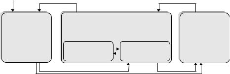
LTE radio interface architecture |
315 |
procedure to enter the LTE_ACTIVE state. LTE_DETACHED is mainly a state used at power-up; once the mobile terminal has registered with the network, it is typically in one of the other states, LTE_ACTIVE or LTE_IDLE.
LTE_ACTIVE is the state used when the mobile terminal is active with transmitting and receiving data. In this state, the mobile terminal is connected to a specific cell within the network. One or several IP addresses have been assigned to the mobile terminal, as well as an identity of the terminal, the Cell Radio-Network Temporary Identifier (C-RNTI), used for signaling purposes between the mobile terminal and the network. LTE_ACTIVE can be said to have two substates, IN_SYNC and OUT_OF_SYNC, depending on whether the uplink is synchronized to the network or not. Since LTE uses an orthogonal FDMA/TDMA-based uplink, it is necessary to synchronize the uplink transmission from different mobile terminals such that they arrive at the eNodeB at (approximately) the same time. The procedure for obtaining and maintaining uplink synchronization is described in Chapter 16, but in short the eNodeB measures the arrival time of the transmissions from each actively transmitting mobile terminal and sends timing-correction commands in the downlink. As long as the uplink is in IN_SYNC, uplink transmission of user data and L1/L2 control signaling is possible. In case no uplink transmission has taken place within a given time window, timing alignment is obviously not possible and the uplink is declared to be OUT-OF-SYNC. In this case, the mobile terminal needs to perform a random-access procedure to restore uplink synchronization.
LTE_IDLE is a low activity state in which the mobile terminal sleeps most of the time in order to reduce battery consumption. Uplink synchronization is not maintained and hence the only uplink transmission activity that may take place is random access to move to LTE_ACTIVE. In the downlink, the mobile terminal can periodically wake up in order to be paged for incoming calls as described in Chapter 17. The mobile terminal keeps its IP address(es) and other internal information in order to rapidly move to LTE_ACTIVE when necessary. The position of the mobile terminal is partially known to the network such that the network knows at least the group of cells in which paging of the mobile terminal is to be done.
15.5Data flow
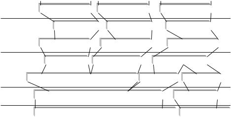
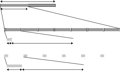
To summarize the flow of downlink data through all the protocol layers, an example illustration for a case with three IP packets, two on one radio bearer and one on another radio bearer, is given in Figure 15.10. The data flow in case of uplink transmission is similar. The PDCP performs (optional) IP header compression, followed by ciphering. A PDCP header is added, carrying information required for deciphering in the mobile terminal. The output from the PDCP is fed to the RLC.
316 |
|
|
|
|
|
|
|
|
|
|
|
3G Evolution: HSPA and LTE for Mobile Broadband |
||||||||||||||||||||||||
|
|
|
|
|
|
SAE bearer 1 |
|
|
|
|
|
|
SAE bearer 1 |
|
|
|
SAE bearer 2 |
|||||||||||||||||||
|
|
|
|
|
|
|
|
|
|
|
|
|
|
|
|
|
|
|
|
|
|
|
|
|
|
|
|
|
|
|
|
|
|
|
|
|
|
|
|
Header |
Payload |
|
|
|
Header |
|
|
Payload |
|
|
|
Header |
|
|
Payload |
|
|
|
|
|
|
||||||||||||
PDCP |
|
|
|
|
|
|
|
|
|
|
|
|
|
|
|
|
|
|
|
|
|
|
|
|
|
|
|
|
|
|
|
|
|
|
|
|
|
|
|
|
|
Header |
Payload |
|
|
|
|
|
Header |
Payload |
|
|
|
Header |
|
Payload |
|
|
|
|
|
|
|||||||||||
header |
|
|
|
|
|
|
|
|
|
|
|
|
|
|
|
|
|
|
|
|
||||||||||||||||
compression, |
|
|
|
|
|
|
|
|
|
|
|
|
|
|
|
|
|
|
|
|
|
|
|
|
|
|
|
|
|
|
|
|
|
|
|
|
ciphering |
|
|
|
|
|
|
|
|
|
|
|
|
|
|
|
|
|
|
|
|
|
|
|
|
|
|
|
|
|
|
|
|
|
|
|
|
|
|
|
PDCP |
PDCP SDU |
|
|
|
|
PDCP |
|
PDCP SDU |
|
|
|
|
PDCP |
|
|
PDCP SDU |
|
|
|
||||||||||||||
|
|
|
header |
|
|
|
|
header |
|
|
|
|
|
header |
|
|
|
|
|
|||||||||||||||||
RLC |
|
|
|
|
|
|
|
|
|
|
|
|
|
|
|
|
|
|
|
|
|
|
|
|
|
|
|
|
|
|
|
|
|
|
|
|
|
|
|
|
|
RLC SDU |
|
|
|
|
|
RLC SDU |
|
|
|
|
|
|
RLC SDU |
|
|
|
|
|
|
|
|||||||||||
segmentation, |
|
|
|
|
|
|
|
|
|
|
|
|
|
|
|
|
|
|
|
|||||||||||||||||
concatenation |
|
|
|
|
|
|
|
|
|
|
|
|
|
|
|
|
|
|
|
|
|
|
|
|
|
|
|
|
|
|
|
|
|
|
|
|
|
|
|
|
|
|
|
|
|
|
|
|
|
|
|
|
|
|
|
|
|
|
|
|
|
|
|
|
|
|
|
|
|
|
|
||
|
RLC |
|
|
|
|
|
|
|
|
|
|
|
|
|
|
|
RLC |
|
|
|
|
|
|
RLC |
|
|
|
|
|
|||||||
|
header |
|
|
|
|
|
|
|
|
|
|
|
|
|
|
header |
|
|
|
|
|
header |
|
|
|
|
|
|||||||||
MAC |
|
|
|
|
|
|
|
|
|
|
|
|
|
|
|
|
|
|
|
|
|
|
|
|
|
|
|
|
|
|
|
|
|
|
||
|
MAC |
|
|
|
|
|
MAC SDU |
|
|
|
|
|
|
|
|
|
MAC |
|
MAC SDU |
|
|
|
|
|||||||||||||
multiplexing |
|
header |
|
|
|
|
|
|
|
|
|
|
|
|
|
|
header |
|
|
|
||||||||||||||||
PHY |
|
|
|
|
|
|
|
|
|
|
|
|
|
|
|
|
|
|
|
|
|
|
|
|
|
|
|
|
|
|
|
|
|
|||
|
|
|
|
|
|
|
Transport block |
|
|
|
|
|
|
CRC |
|
|
Transport block |
CRC |
|
|||||||||||||||||
|
|
|
|
|
|
|
|
|
|
|
|
|
|
|
|
|
|
|
|
|
|
|
|
|
|
|
|
|
|
|
|
|
|
|
|
|
Figure 15.10 Example of LTE data flow.
The RLC protocol performs concatenation and/or segmentation of the PDCP SDUs and adds an RLC header. The header is used for in-sequence delivery (per logical channel) in the mobile terminal and for identification of RLC PDUs in case of retransmissions. The RLC PDUs are forwarded to the MAC layer, which takes a number of RLC PDUs, assembles those into a MAC SDU, and attaches the MAC header to form a transport block. The transport-block size depends on the instantaneous data rate selected by the link adaptation mechanism. Thus, the link adaptation affects both the MAC and RLC processing. Finally, the physical layer attaches a CRC to the transport block for error-detection purposes, performs coding and modulation, and transmits the resulting signal over the air.
320 |
3G Evolution: HSPA and LTE for Mobile Broadband |
specification purely as a tool to define different time intervals and does not impose any specific transmitter and/or receiver implementation constraints, e.g. a certain sampling rate. In practice, an FFT-based transmitter/receiver implementation with NFFT = 2048 and a corresponding sampling rate fs = 30.72 MHz is suitable for the wider LTE transmission bandwidths, such as bandwidths in the order of 15 MHz and above. However, for smaller transmission bandwidths, a smaller FFT size and a correspondingly lower sampling rate can very well be used. As an example, for transmission bandwidths in the order of 5 MHz, an FFT size NFFT = 512 and a corresponding sampling rate fs = 7.68 MHz may be sufficient.
One argument for adopting a 15 kHz subcarrier spacing for LTE was that it may simplify the implementation of WCDMA/HSPA/LTE multi-mode terminals. Assuming a power-of-two FFT size and a subcarrier spacing f = 15 kHz, the sampling rate fs = f · NFFT will be a multiple or sub-multiple of the WCDMA/HSPA chip rate fcr = 3.84 MHz. Multi-mode WCDMA/HSPA/LTE terminals can then straightforwardly be implemented with a single clock circuitry.
In addition to the 15 kHz subcarrier spacing, a reduced subcarrier spacingflow = 7.5 kHz is also defined for LTE. The reduced subcarrier spacing specifically targets MBSFN-based multicast/broadcast transmissions as will be further discussed in Section 16.2.6. The remaining discussions within this and the following chapters will assume the 15 kHz subcarrier spacing unless explicitly stated otherwise.
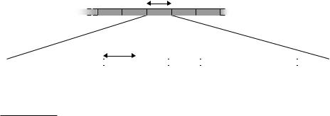
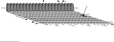
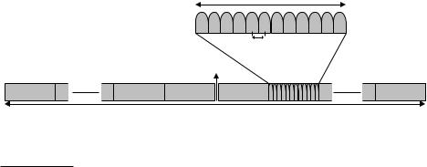
As illustrated in Figure 16.4, in the frequency domain the downlink subcarriers are grouped into resource blocks, where each resource block consists of 12 consecutive subcarriers3 corresponding to a nominal resource-block bandwidth of 180 kHz. In addition, there is an unused DC-subcarrier in the center of the downlink spectrum. The reason why the DC-subcarrier is not used for any transmission is that it may
One resource block (12 subcarriers, 180 kHz)
f 15 kHz
DC - subcarrier
NRB resource blocks (12NRB 1 subcarrier)
Figure 16.4 LTE downlink frequency-domain structure.
3 The resource blocks are actually two-dimensional (time-frequency) units with a size of 12 subcarriers times one 0.5 ms slot (7/6 OFDM symbols), see also Figure 16.6.
322 |
3G Evolution: HSPA and LTE for Mobile Broadband |
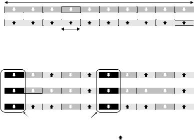
According to Chapter 4, a subcarrier spacing f = 15 kHz corresponds to a useful symbol time Tu = 1/ f ≈ 66.7 µs (2048 · Ts). The overall OFDM symbol time is then the sum of the useful symbol time and the cyclic-prefix length TCP. As illustrated in Figure 16.5, LTE defines two cyclic-prefix lengths, the normal cyclic prefix and an extended cyclic prefix, corresponding to seven and six OFDM symbols per slot, respectively. The exact cyclic-prefix lengths, expressed in the basic time unit Ts, are given in Figure 16.5. It should be noted that, in case of the normal cyclic prefix, the cyclic-prefix length for the first OFDM symbol of a slot is somewhat larger, compared to the remaining OFDM symbols. The reason for this is simply to fill the entire 0.5 ms slot as the number of time units Ts per slot (15360) is not dividable by seven.
The reasons for defining two cyclic-prefix lengths for LTE are twofold:
1.A longer cyclic prefix, although less efficient from an overhead point-of-view, may be beneficial in specific environments with very extensive delay spread, for example in very large cells. It is important to have in mind though that a longer cyclic prefix is not necessarily beneficial in case of large cells, even if the delay spread is very extensive in such cases. If, in large cells, link performance is limited by noise rather than by signal corruption due to residual time dispersion not covered by the cyclic prefix, the additional robustness to radio-channel time dispersion, due to the use of a longer cyclic prefix, may not justify the corresponding loss in terms of received signal energy.
2.As already discussed in Chapter 4, in case of MBSFN-based multicast/broadcast transmission, the cyclic prefix should not only cover the main part of the actual channel time dispersion but also the main part of the timing difference between the transmissions received from the cells involved in the MBSFN transmission. In case of MBSFN operation, the extended cyclic prefix is therefore typically needed.
Thus, the main use of the LTE extended cyclic prefix is expected to be MBSFNbased transmission. It should be noted that different cyclic-prefix lengths may be used for different subframes within a frame. As an example, MBSFN-based multicast/broadcast transmission may be confined to certain subframes in which case the use of the extended cyclic prefix, with its associated additional cyclic-prefix overhead, should only be applied to these subframes.
Taking into account also the downlink time-domain structure, the resource blocks mentioned above consist of 12 subcarriers during a 0.5 ms slot, as illustrated in Figure 16.6. Each resource block thus consists of 12 · 7 = 84 resource elements in case of normal cyclic prefix and 12 · 6 = 72 resource elements in case of extended cyclic prefix.