

Учебное пособие 2254
.pdfRussian Journal of Building Construction and Architecture
can cause technologically unacceptable warming of mixes. As a result, heat release in thin 3D-printed structures might provoke significant thermal stresses, deformations, and cracking.
Conclusion. For types of 3D-printable decorative mixes have been obtained using white and grey Portland cement with different particle sizes. It has been established that kind of cement as a factor changing the properties of solid phase in the 3D-printable mixture is an effective method for plasticity regulation and increasing its resistance to load during printing. The shape stability of a 3D-printable mixture can be changed by 2––3 times by means of using cement with efficient ranging of particle size. The 3D-printable mix with CEM I 42.5 R (grey) having ~ 70 % particle with 30––50 µm is characterized by the optimal plasticity, structural strength, and deformability under the load. Using CEM I 52.5 R (white) having ~ 45 % particle with 30––50 µm impairs these characteristics of mixes.
The fresh mixes of 3D-printable decorative concrete had the plastic yield value
Ki 1.0––2.2 kPa which is defined the ability of these mixes to plastically deform without structure destruction and maintain their stability during extrusion. At the same time, all sthe
ystems with grey Portland cement had a sufficient |
shape stability (structural strength |
0 = 1.5––4.5 kPa, the value of plastic deformations |
pl = 0.03––0.05 mm/mm) which is |
characterized by the ability of the system to retain its form, resist the deformation under compressions load during multi-layer casting.
The addition of viscosity modifiers with various compositions raises the plastic strength of the mixes by three to five times. It is possible if silicate and aluminosilicate modifier (metakaolin) is used. The reason is that they are similar in their crystal-chemical structure to hydrate phases in the cement systems. The effect of the gum + K4P2O7 combined modifier is determined by its impact on the dispersion medium of the cement system. The role of gum is to increase its density and viscosity, while reducing the hydration activity of water molecules. The role of K4P2O7 as a strong electrolyte is to change the ionic strength of the solution and raise its supersaturation. As a result, the addition of this modifier allows one to effectively control only the rheological characteristics of the cement systems.
The optimal rheological characteristics of fresh mixes with CEM I 52.5 R (white) can be achieved by means of using metakaolin as a dispersed adsorption-active inorganic modifier changes the geometric and energetic conditions in the volume of the disperse system.
References
1.Slavcheva G., Artamonova O. Reologicheskoe povedenie dispersnykh sistem dlya stroitel'noi 3D-pechati: problema upravleniya i vozmozhnosti arsenala «nano» [The rheological behavior of disperse systems for 3d printing in construction: the problem of control and possibility of «nano» tools application]. Nanotekhnologii v stroi-tel'stve: nauchnyi internet-zhurnal, 2018, no. 10, pp. 107––122.
80
Issue № 4 (52), 2021 |
ISSN 2542-0526 |
2.Ur'ev N. B. Fiziko-khimicheskaya dinamika strukturirovannykh nanodispersnykh sistem i nanodispers-nykh kompozitsionnykh materialov. Chast' 1 [Physico-chemical dynamics of structured nanodispersed systems and nanodispersed composite materials. Part 1]. Fizikokhimiya poverkhnosti i zashchita materialov, 2010, no. 46, pp. 3––23.
3.Benini H. Concreto Arquitetônico e Decorativo en Concreto. Ensino, Pesquisa E Reliazações, IBRACON, 2007, pp. 1413—1551.
4.Benítez A., Bálsamo H. Hormigones arquitectónicos: blancos y coloreados. Hormigones Especiales, AATH, 2004, pp. 75—90.
5.De Schutter G., Lesage K., Mechtcherine V., Nerella V. N., Habert G. & Agusti-Juan I. Vision of 3D printing with concrete-technical, economic and environmental potentials. Cement and Concrete Research, 2018, vol. 112, pp. 25—36.
6.Fernández Gómez J. Estructuras de concreto aparente. Simposio Internacional sobre Concretos Especiais, 2000, pp. 1—22.
7.Figueiredo S. C., Çopuroğlu O., Schlangen E. Effect of viscosity modifier admixture on Portland cement paste hydration and microstructure. Construction and Building Materials, 2019, vol. 212, pp. 818—840. doi: 10.1016/j.conbuildmat.2019.04.020
8.Hou S., Duan Z., Xiao J., Ye J. A review of 3D printed concrete: Performance requirements, testing
measurements and mix design. Construction and Building Materials, 2021, vol. 273, pp. 121745. doi: 10.1016/j.conbuildmat.2020.121745
9.Jayathilakage R., Rajeev P., Sanjayan J. G. Yield stress criteria to assess the buildability of 3D concrete
prin-ting. |
Construction |
and |
Building |
Materials, |
2020, |
vol. |
240, |
pp. |
117989. |
doi: 10.1016/j.conbuildmat.2019.117989 |
|
|
|
|
|
|
|||
10.Khan M. A. Mix suitable for concrete 3D printing: A review. Materials today: Proceedings, 2020, vol. 32 (4), pp. 831—837. doi: 10.1016/j.matpr.2020.03.825
11.Labonnote N., Rоnnquist A., Manum B., Rüther P. Additive construction: State-of-the-art, challenges and opportunities. Autom. Constr, 2016, vol. 72, pp. 347—366.
12.López A., Guzmán G. A., Di Sarli A. R. Color stability in mortars and concretes. Part 1: Study on architectural mortars. Constr. Build. Mater, 2016, vol. 120, pp. 617—622. doi: 10.1016/j.conbuildmat.2016.05.133.
13.López A., Guzmán G. A., Di Sarli A. R. Color stabilityin mortars and concretes. Part 2: Studyon architectural concretes. Constr. Build. Mater, 2016, vol. 123, pp. 248—253. doi: 10.1016/j.conbuildmat.2016.06.147.
14.Ma G. W., Wang L. A critical review of preparation design and workability measurement of concrete material for largescale 3D printing. Front Struct Civil Eng, 2018, vol. 12 (3), pp. 382—400. doi: 10.1007/s11709- 017-0430-x.
15.Marchon D., Kawashima S., Bessaies-Bey H., Mantellato S., Ng S. Hydration and rheology control of concrete for digital fabrication: Potential admixtures and cement chemistry. Cement and Concrete Research, 2018, vol. 112, pp. 96—110. doi: 10.1016/j.cemconres.2018.05.014.
16.Soltan D. G., Li V. C. A self-reinforced cementitious composite for building-scale 3D printing. Cem Concr Compos, 2018, vol. 90, pp. 1—13. doi: 10.1016/j.cemconcomp.2018.03.017.
17.Souza M. T., Ferreira I. M., Guzi de Moraes E., Senff L., Novaes de Oliveira A. P. 3D printed concrete for large-scale buildings: An overview of rheology, printing parameters, chemical admixtures, reinforcements, and economic and environmental prospects. Journal of Building Engineering, 2020, vol. 32, pp. 101833. doi: 10.1016/j.jobe.2020.101833.
18.Vergara L. A., Colorado H. A. Additive manufacturing of Portland cement pastes with additions of kaolin, superplastificant and calcium carbonate. Construction and Building Materials, 2020, vol. 248, pp. 118669. doi: 10.1016/j.conbuildmat.2020.118669.
19.Wangler T., Roussel N., Bos F. P., Salet A. M., Flatt R. J. Digital Concrete: A Review. Cement and Concrete Research, 2019, vol. 123, pp. 105780. doi: 105780. 10.1016/j.cemconres.2019.105780.
20.Yu K., Mc Gee W., Ng T. Y., Zhu H., Li V. C. 3D-printable engineered cementitious composites (3DP-ECC): Fresh and hardened properties. Cement and Concrete Research, 2021, vol. 143, pp. 106388. doi: 10.1016/j.cemconres.2021.106388.
21.Yuan Q., Zhou D., Khayat K. H., Feys D., Shi C. On the measurement of evolution of structural build-up of cement paste with time bystatic yield stress test vs. small amplitude oscillatoryshear test. Cem. Concr. Res, 2017, vol. 99, pp. 183—189. doi: 10.1016/j.cemconres.2017.05.014.
22.Zahia T., Roussel N., Lanos C. The squeezing test: a tool to identify firm cement-based material’s rheological behaviour and evaluate their extrusion ability. Cem. Concr. Res, 2005, vol. 35, pp. 1891—1899. doi: 10.1016/j.cemconres.2004.09.007.
23.Zhang Y., Zhang Y., Liu G., Yang Y., Wu M., Pang B. Fresh properties of a novel 3D printing concrete ink. Construction and BuildingMaterials, 2018, vol. 174, pp. 263—271. doi: 10.1016/j.conbuildmat.2018.04.115.
81

Russian Journal of Building Construction and Architecture
DOI10.36622/VSTU.2021.52.4.008
UDC 666.9.03
Vijayvenkatesh Chandrasekaran1, Rahul Reddy Rajupalem2
BEHAVIOUR OF TERNARY BLENDED CEMENT CONCRETE SLAB
WITH STEEL FIBER UNDER IMPACT LOADING
SASTRA University1, 2
Thanjavur-613401, India
1M. Tech Graduate in Structural Engineering, School of Civil Engineering, e-mail: ramathutham@gmail.com 2M. Tech Graduate in Structural Engineering, School of Civil Engineering
Statement of the problem. An experimental investigation of impact strength of ternary blended cement concrete slab with steel fiber under impact loading was carried out. The amount of replacement of binder with Flyash varies from 10 to 30 % in step of 10 %, glass powder from 20 to 40 % in step of 10 % and fiber volume fraction from 0.75 to 2.25 % in step of 0.75 %. Parametric performance of ten 600 × 600 mm, 60mm thick reinforced concrete slabs was evaluated. The impact test on the slab was conducted bydropping a steel ball from a height of 457 mm under impact setup. The parameters like failure mode, the impact energyof first crack and ultimate crack failure, ductility index, failure pattern, ultimate crack resistance, crack resistance ratio were investigated when subjected to impact load.
Results. The test results reported that the slab specimen S7 shows better performance in strength.
Keywords: Impact loading, Flyash, Steel fibers, Concrete slab.
Introduction. Lots of structures are exposed to possible harms caused by the unexpected loads. Therefore we have to take better care of the structure and its components must be impact resistant and stable. In order to resist the impact loads, the concrete structures have to be planned. Although the use of reinforced concrete slabs is growing now a days, the influence of various parameters is not properly evaluated. In the current study, an investigation of impact strength of ternary blended concrete slab with steel fibre under impact loading has been conducted. The amount of replacement of binder with fly ash varies from 10––30 % in step of 10 %, glass powder from 20 to 40% in step of 10% and steel fibre percentage from 0.75 to 2.25 % in the step of 0.75 %. Parametric performance of 600 mm × 600 mm × 60 mm thick reinforced concrete slabs viz. failure mode, the impact energy of CI and UC failure, ductility index, failure pattern, UCR, UCRR, were investigated when subjected to impact load.
It follows the previous studies, e.g., S. TanerYildirim et al [1] investigated the properties of hybrid fiber reinforced concrete against impact loads. In this study, SFRC, GFRC and PFRC structures were investigated. 12 different concrete series were casted, one is fibre less and the
© Chandrasekaran Vijayvenkatesh, Rajupalem Rahul Reddy, 2021
82
Issue № 4 (52), 2021 |
ISSN 2542-0526 |
others reinforced with steel, glass and polypropylene were prepared. A drop-weight test was conducted and cured for 28 days. The initial crack formation was identified. The results showed that the performance of impact strength increased in SFRC, the positive effect was observed in the hybrid fibres on the performance of concrete. Tarek H. Almusallam Aref et al [2] investigated the hybrid fibres effectiveness in the RC slabs, which improves the impact resistance. In this study, 27 concrete slab specimens were casted and tested. The geometrical properties of the fibres and their different quantities were studied. The experimental test data and the other test data of fibres was compared. A good agreement was observed between the test results and the general results. Doo Yeol Yoo et al. [3] discussed the impact resistance of FRC. In this study, the properties of FRC against impact loadings train rate sensitivity were discussed. Under various different loading conditions, the impact resistance of FRC with various fibres was investigated. Compared to plain concrete, fibre reinforced concrete of impact resistance was improved. H. A. Abdalla [4] determined the deflection in concrete members reinforced with FRP bars. In this study, the deflection of FRP bars subjected to the flexural stresses is described. Seven concrete specimens of GFRP, CFRP were casted. The casted specimens were tested under a different loading. The experimental results and the predicted results were compared. Based on the test results, the analytical methods were justified. A good agreement was observed between the analytical methods and the experimental ones. Hamid Sadraie et al. [5] investigated the performance of SFRP and GFRP against impact loading. In this paper, the effect of concrete strength, slab thickness, reinforcement amount and arrangement of reinforcement of concrete slabs was examined using both the experimental and numerical methods. 13 specimens of 1000 mm × 1000 mm × 75 mm concrete slabs and 2 ones of 1000 mm × 1000 mm × 100 mm concrete slabs were experimentally investigated against impact loading. The various parameters were studied and compared. Good results were obtained by means of the experimental and numerical methods. OguzAkNnDuzgun et al. [6] determined the mechanical properties of lightweight aggregate concrete. To examine the steel fiber ratio of concrete, instead of natural aggregate various percentage of pumice were used by volume, various percentage of steel fiber was used by volume, cement content and slump were used. The inclusion of more percentage of steel fibre in the concrete compressive strength, tensile strength, unit weight was increased compared to the conventional specimen. The result shows the deformation and modulus of elasticity were decreased. Leila Soufeiani et al [7] developed the influence of the volume fraction and shape of steel fibers on FRC against dynamic loading. The fraction of the volume and the shape of steel fibres play a vital role among the properties of the SFRC. In the present study, the material response was identi-
83

Russian Journal of Building Construction and Architecture
fied under impact test. The structural responses of the various types of FRC with steel fibers were compared. Fethi Sermet and Anil Ozdemir [8] investigated the Punching behaviour of SFRC and PFRC slabs under normal loading. In this study, the performance of plain, SFRC and PFRC slabs were compared experimentally. 3 specimens of 1000 mm × 1000 mm × 100 mm thick were casted where reference specimen, SFRC and PFRC were prepared and normal load was applied. In the experimental study, the first stage shows the load-displacement curve results and the second stage shows the punching performances of specimens under normal loads were compared. Tohid Mousavi [9] investigated the impact response of HFRC slabs. In this study, the investigation of SRC slabs against impact loading has been performed. This paper mostly described the minimum deflection and less structure damage against impact loading. Hybrid FRP-SRC slabs were casted. The experimental results were verified and extended for analytical study against impact loading. By means of the analytical method, the structural response was extracted. According to the results, the deflection and damage in concrete was minimized. Cengiz Duran Atisand Okan Karahan [10] determined the properties of SFRC. In the present study, various parameters were included. Various fly ash percentage and steel fibre dosage was used. The addition of steel fiber shows an improvement of the properties of tensile strength, and shrinkage. And also it reducesthe workability and increased the sorptivity. The fly ash concrete is observed to be similar to the PCC. EetharThanonDawoodand MahyuddinRamli [11] identified a higher strength of cement mortar reinforced with hybrid fibers. In this experimental study, the fibre dosage used was 2 %. To discuss the effect of hybrid fibres, compressive, tensile, flexural strength, shrinkage, modulus of elasticity were determined. According to the results, the compressive strength, flexural toughness, tensile strength were improved. Young Keun Cho et al. [12] developed the effects of fly ash on compressive strength of fly ash cement concrete. In this study, the amorphous and crystalline phase effects on the compressive strength of FACC was discussed. 25 % of cement was replaced by 16 various types of fly ashes and compressive strength was increased due to differences in pozzolanic reactions and various parameter effects of the fly ash were also analyzed. Based on the compressive strength, FACC was greater in 91 days than in 28 days. Based on the various chemical parameters, a higher correlation has been observed in 91 days thanin 28 days. The great effect has been observed on the chemical properties of fly ash. Victor Marcos-Meson et al [13] investigated the corrosion resistance of SFRC. Nowadays, SFRC is being used in civil industry. This paper represents the corrosion of SFRC, due to the damage in the fibre matrix the worst section when exposed to carbonation and chlorides was proposed. Good results were observed in the durability of noncracked SFRC. The durability of cracked SFRC is not discussed in this literature.
84
Issue № 4 (52), 2021 |
ISSN 2542-0526 |
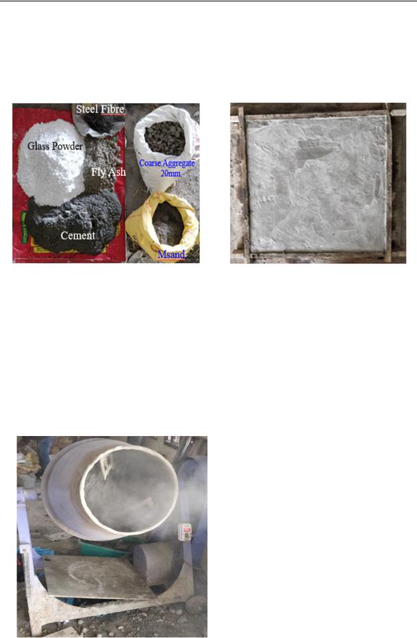
1. Raw Materials. Due to its availability in the market, an Ordinary Portland Cement was used as the main binder in the concrete slab. The concrete is Grade 53. The fine aggregate (M-Sand) is a substitute of river sand which was used with the nominal size of less than 4.75 mm collected locally. The specific gravity test for fine aggregate was conducted and the value was 2.36. The coarse aggregates of crushed stone with the nominal size from 12.5 mm to 20 mm was collected in the local market. The specific gravity test for coarse aggregates (20 mm) was also conducted and the value was 2.84. The fly ash which purchased from the local market was used in this study with the dosage of 10 % varying from 10 to 30 %. The glass powder purchased from the market was used in the concrete slab with the dosage of 10 % varying from 20 to 40 %. The super plasticizer of SP-550 was used to reduce the water content. The water content dosage was 0.7 % by weight of cement. The crimped steel fibre purchased from the market was used in the concrete slab up to the 2.5 % by the volume. The steel fibre properties are listed in the Table 1.
|
|
Fibre properties |
|
Table 1 |
|
|
|
|
|
||
|
|
|
|
|
|
Type of fibre |
Length |
Diameter |
|
Aspect ratio |
Tensile strength |
(mm) |
(mm) |
|
(MPa) |
||
|
|
|
|||
Crimped steel fibre |
50 |
1 |
|
50 |
>1100 |
2. Mix proportion. In the current study, the concrete slab specimens have been prepared with W/C ratio of 0.4 which remains constant for all slabs. If any voids are formed, to fill them in the concrete slabs, steel fibres and coarse aggregates were used. The total of 10 specimens were casted, one is a control one, the remaining nine consists of 50 % cement and 50 % cementitious material with the varying of crimped steel fibre percentage from 0.75 % to 2.25 % (Table 2).
|
|
|
|
|
|
Mix proportions of various specimens |
|
|
|
|
Table 2 |
|||||
|
|
|
|
|
|
|
|
|
|
|
||||||
|
|
|
|
|
|
|
|
|
|
|
|
|
|
|
|
|
S.no |
Specimen |
|
Cement |
|
Flyash |
Glass |
powder |
Fine aggregate |
Coarse aggregate |
W/C |
Steel |
fibre |
Super plasticizer |
|||
|
|
|
|
|
|
|
|
|
|
|
|
|
|
|
|
|
|
|
|
|
|
|
|
|
|
|
|
|
|
|
|
|
|
|
|
% |
|
Kg/m3 |
% |
Kg/m³ |
% |
|
Kg/m³ |
Kg/m³ |
Kg/m³ |
|
% |
|
Kg/m³ |
Kg/m³ |
1 |
S1 |
100 |
|
430 |
–– |
–– |
–– |
|
–– |
|
|
|
–– |
|
–– |
|
2 |
S2 |
|
|
|
10 |
21.5 |
40 |
|
67.5 |
|
|
|
0.75 |
|
18.83 |
|
3 |
S3 |
|
|
|
20 |
44 |
30 |
|
44 |
|
|
|
1.5 |
|
37.66 |
|
4 |
S4 |
|
|
|
30 |
67.5 |
20 |
|
21.5 |
|
|
|
2.25 |
|
56.5 |
|
5 |
S5 |
50 |
|
380 |
10 |
21.5 |
40 |
|
67.5 |
704 |
1275 |
0.4 |
0.75 |
|
18.83 |
1.75 |
6 |
S6 |
|
20 |
44 |
30 |
|
44 |
1.5 |
|
37.66 |
||||||
7 |
S7 |
|
|
|
30 |
67.5 |
20 |
|
21.5 |
|
|
|
2.25 |
|
56.5 |
|
8 |
S8 |
|
|
|
10 |
21.5 |
40 |
|
67.5 |
|
|
|
0.75 |
|
18.83 |
|
9 |
S9 |
|
|
|
20 |
44 |
30 |
|
44 |
|
|
|
1.5 |
|
37.66 |
|
10 |
S10 |
|
|
|
30 |
67.5 |
20 |
|
21.5 |
|
|
|
2.25 |
|
56.5 |
|
85
Russian Journal of Building Construction and Architecture
3. Specimen preparation. The concrete slabs with steel fibre under impact loading were casted to evaluate the energy. Initially a wooden mould with the dimension of 600 × 600 × 60 mm was prepared for thecasting ofslab. Thewooden mould has been placed onthe leveled surface and oil has beenapplied on itseither sidesto removetheslabeasilyafter setting time.
Fig. 1 Collection of Materials |
Fig. 2 Concrete slab |
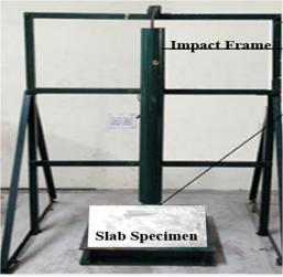
The materials required for the casting of slab have been taken and measured in the weighing machine. The materials were poured in the concrete mixer for mixing after the completion; the concrete was poured inside the wooden mould. A slight compaction is also required to block or seal the voids in the concrete slab. A neat finishing has been done and left to rest for 24 hours for setting, after the setting time the slab has been removed from the wooden mould and cured for 28 days. The same procedure is applied for theremaining slabs. Inaddition, 100 ×100× 100 mm concrete cubes were casted and the compressive strength was tested after 7, 14, 28 days.
Fig. 3. Mixer Machine
86
Issue № 4 (52), 2021 |
ISSN 2542-0526 |
4. Test Setup. According to the ACI Committee 544 the drop weight test was conducted on the concrete slab. The circular ball of mass 3.8 kg at a height of 457 mm was released on the surface of the concrete slab repeatedly. The crack will be generated on the concrete slab by dropping the ball. The crack width was captured with the help of microscope and later the width measured in a special software. Along with the width, crack depth was also measured. The crack formed initially is known as Crack Initiation (CI) and the crack was formed when the specimen failed completely, which is known as Ultimate Crack (UC). The initial crack
energy and ultimate crack energy was calculated using the following equation (1). |
|
Energy = n × m × g × h, |
(1) |
where n is the number of impact blows, m is the steel ball mass (3.8 kg), g is the acceleration of gravity (9.81 m/s2), h is the height of steel ball (457 mm).
The following equations (2) & (3) can be used to calculate UCR and UCRR |
|
UCR = Energy / (L × W × D), |
(2) |
UCRR = UCR / fck, |
(3) |
where L is the length of the crack observed in the slab specimen, W is the maximum width of the crack observed in the slab specimen, D is the maximum depth of the crack observed in the slab specimen, fck is the compressive strength of the cube after 28 days.
Fig. 4. Impact test setup
5.Results and Discussion. From the experimental work, the obtained results are explained in this section where compressive strength, energy at initial crack and final or ultimate crack, crack depth and crack width results, ductility index, failure pattern, ultimate crack resistance, crack resistance ratio are investigated.
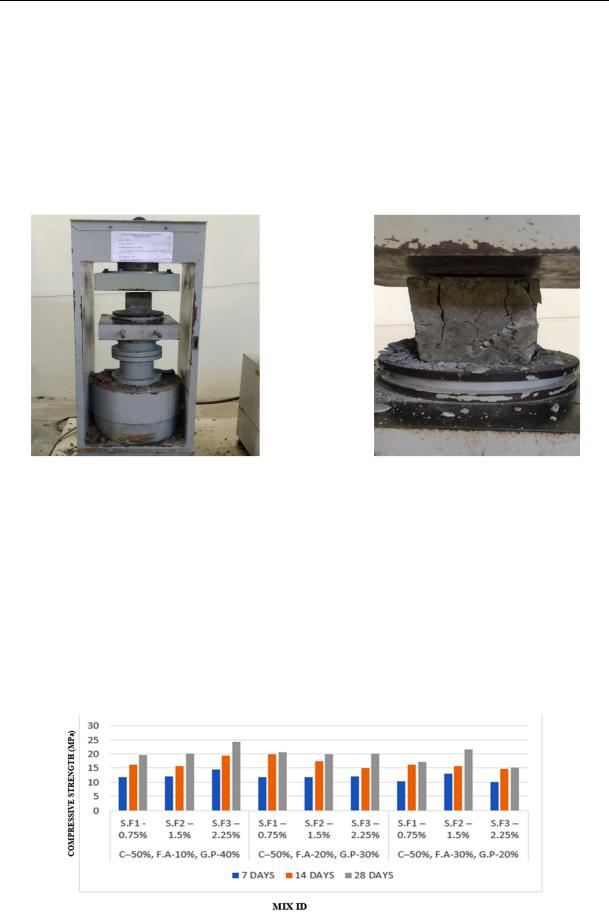
6.Compressive Strength. The 100 mm cubes were tested for the compressive strength after 7, 14, 28 days with the dosage of steel fibre of up to 2.25 %. According to the codal provision IS 516:2000, the standard cube results were studied without the inclusion of steel fibre. The
87
Russian Journal of Building Construction and Architecture
obtained compressive strength results of the cubes is listed in Table 3. The maximum compressive strength was observed in the cubes C3 and C8. The compressive strength results is listed in Fig. 4. In concrete the usage of steel fibre content is limited to 2.5 % by volume. In the present study (Ternary blended concrete slab), the usage of cement is 50 %. In this case, the compressive strength achieved is 70 to 80 % of the normal (plain) concrete. Addition of steel fibres up to 5 to 6 % will increase the strength by about 2.5 times of the normal (plain) concrete.
Fig. 5. Compression Test
|
|
Compressive strength of cubes after 7, 14, 28 days (MPA) |
Table 3 |
|||
|
|
|
||||
|
|
|
|
|
|
|
|
Specimen |
|
|
7 days |
14 days |
28 days |
C1 |
C –– 50 %, |
|
S.F1 –– 0.75 % |
11.75 |
16.10 |
19.59 |
C2 |
F.A –– 10 %, |
|
S.F2 –– 1.5 % |
12.12 |
15.78 |
20.21 |
C3 |
G.P –– 40 % |
|
S.F3 –– 2.25 % |
14.55 |
19.31 |
24.26 |
C4 |
C –– 50 %, |
|
S.F1 –– 0.75 % |
11.79 |
19.81 |
20.66 |
C5 |
F.A –– 20 %, |
|
S.F2 –– 1.5 % |
11.84 |
17.30 |
19.74 |
C6 |
G.P –– 30 % |
|
S.F3 ––2.25 % |
12.00 |
15.02 |
20.00 |
C7 |
C –– 50 %, |
|
S.F1 ––0.75 % |
10.34 |
16.12 |
17.24 |
C8 |
F.A –– 30 %, |
|
S.F2 ––1.5 % |
12.90 |
15.73 |
21.50 |
C9 |
G.P –– 20 % |
|
S.F3 ––2.25 % |
10.12 |
14.75 |
15.21 |
Fig. 6. Compressive strength results
88
Issue № 4 (52), 2021 |
ISSN 2542-0526 |
7. Crack Width and Crack Resistance. Due to punching, the formation of cracks were identified from the middle of the slab. The maximum width of the crack was captured by means of the USBM-5S digital USB microscope. It has the focus point range from 50× to 500× in the built-in white light Led which is adjustable by control wheel. The opening of the crack, i.e., initial crack, was less pronounced in the specimen S7 compared to the other specimens. The width of the crack of specimen S7 was reduced by 14 % compared to the other specimens, and the width of the crack of specimen S7 was reduced by 11 % compared to the control specimen. The ultimate crack was less pronounced in specimen S7 compared to the other specimens. The ultimate width of the crack of specimen S7 was reduced by 13 % compared to specimens S4 and S10. The ultimate crack width of specimen S10 was decreased by 8.9 % compared to specimen S6. The crack width at the ultimate of specimen S7 was decreased by 26 compared to the control specimen. The steel fibre addition of 2.25 % to the specimen S7 minimizes the opening of the crack and also has more blows for ultimate crack against the impact loading. Due to the increasing number of blows in the concrete slab specimen, the maximum length and width ofthecracks were increased against impact loading. The UCR and UCRR for fibre reinforced concrete slabs (FRCS) are listed in Table 4. Compared to the all fibre reinforced concrete slabs (FRCS), specimen S10 has a higher UCR and UCRR. The UCR and UCRR were very low for specimen S2.
|
|
|
Crack resistance of concrete slabs |
|
Table 4 |
|||
|
|
|
|
|
||||
|
|
|
|
|
|
|
|
|
S.no |
Specimen |
Comp strength |
|
Dimensions |
|
Ultimate CR |
Ultimate CRR |
|
total length |
Maxdepth |
slab |
||||||
(N/mm2) |
(N/mm2) |
|||||||
|
|
|
(mm) |
(mm) |
depth(mm) |
|
|
|
1 |
S1 |
–– |
–– |
–– |
–– |
–– |
–– |
|
2 |
S2 |
19.52 |
1032 |
9.8 |
60 |
0.69 |
0.04 |
|
3 |
S3 |
20.21 |
969 |
4.19 |
60 |
2.16 |
0.11 |
|
4 |
S4 |
24.26 |
989 |
0.58 |
60 |
27.05 |
1.12 |
|
5 |
S5 |
20.66 |
952 |
9.63 |
60 |
1.05 |
0.05 |
|
6 |
S6 |
19.74 |
1031 |
3.24 |
60 |
4.12 |
0.21 |
|
7 |
S7 |
20.00 |
1045 |
1.18 |
60 |
17.33 |
0.87 |
|
8 |
S8 |
17.24 |
1022 |
0.47 |
60 |
21.34 |
1.24 |
|
9 |
S9 |
21.50 |
1159 |
2.79 |
60 |
3.80 |
0.18 |
|
10 |
S10 |
15.21 |
1042 |
0.28 |
60 |
53.18 |
3.50 |
|
8. Failure Patterns. The failure patterns of various specimens under impact loading were shown in the following figures 7ato 7j. In the concrete slabs, shear crack failures occurred at the top of the slab. Due to the increasing number of blows the failure patterns of specimen S7 were found to be less compared to the control specimen and the other ones of the slab. Among the fibre reinforced concrete slab specimens S7, S10, S4 the damaged level was a little bit less with more blows compared to the other specimens except the control one where there was a
89