

Учебное пособие 2254
.pdfRussian Journal of Building Construction and Architecture
experimental data by N. V. Fedorova and M. D. Medyankin for class B70 concretes, the value is much less and amounted to = 22 sec-1. Accordingly, the value of the coefficient of increasing the dynamic strength of concrete bst d is 1.19. It should be noted in the Russian
standards SP (СП) 385.1325800.2018, for all modes of static-dynamic loading bst d = 1.15 is accepted, which causes underestimation of the value of the dynamic strength of concrete of structures in a specific range of dynamic reloading time and to an even greater one with a decrease in the time of special impact. In the U.S. standards, the value of this coefficient while calculating buildings for progressive destruction for all modes of static-dynamic loading is also assumed to be constant but equalto bst d = 1.25 [15, 20].
In order to examine the influence of the parameter characterizing the ductile resistance of concrete and, accordingly, the coefficient of increase in its static-dynamic strength in more detail, three variants of the dynamic analysis of the stress-strain state of the structure were performed according to the secondary design scheme using different values bst d : 1 is accor-ding to G. A. Geniev, 2 is according to N. V. Fedorova and M. D. Medyankin, and 3 is according to the Russian norms of SP (СП) 385.1325800.2018. In this case, the coefficient of increasing the dynamic strength of reinforcement for all calculation options was taken equal to 1.2.
|
|
|
|
|
Table 2 |
|
Input parameters of diagrams of static-dynamic deformation of materials for dynamic analysis |
||||
|
of a structural system according to a secondarydesign scheme |
|
|||
|
|
|
|
|
|
|
|
|
|
Parameter characterizing |
Coefficient of the |
|
|
Level of |
Time of dynamic |
the viscous resistance |
increase in the |
|
|
static loading |
extra loading |
of concrete |
static and |
|
|
|
|
dynamic strength |
|
|
|
|
|
|
|
|
|
|
td (sec) |
(sec-1) |
bst d |
|
According to the |
|
|
|
|
|
experimental data |
|
|
314 |
1.0018 |
V70 |
byG. A. Geniev |
0.3 |
0.19 |
|
|
According to the |
|
|
|||
Concrete |
experimental data by |
|
|
22 |
1.19 |
N. V. Fedorova |
|
|
|||
|
|
|
|||
|
|
|
|
|
|
|
and M. D. Medyankin |
|
|
|
|
|
According to the Rus- |
|
|
|
|
|
sian standards SP (СП) |
–– |
–– |
- |
1.15 |
|
385.1325800.2018 |
|
|
|
|
|
|
Reinforcement А500 |
|
1.2 |
|
5. Results of numerical studies and their analysis. The analysis of the results of a numerical study of the deformation of the frame elements of a multi-storey building under the considered loads enabled us to conclude the following. At the first stage of loading the frame with
30
Issue № 4 (52), 2021 |
ISSN 2542-0526 |
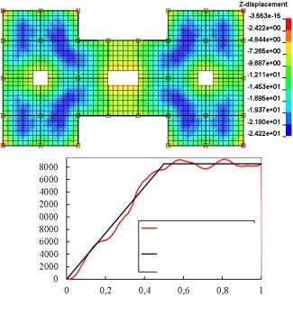
a stage-by-stage distributed load of 8 kn/m2, the maximum displacement of the monolithic slab of the upper floor slab was –24.22 mm or 1/310 of the span (Fig. 5a).
а
b
Longitudinal effort, MN
Under quasistatic loading
Under static loading
Time, sec
Fig. 5. Mosaic of vertical displacements in the floor disks (a) and the graph of the longitudinal force and time in the B2 column at the first stage of loading
As already noted, the quasi-static application of this load was achieved by means of the method of dynamic relaxation. The effectiveness of this method can be seen from Fig. 5b where static loading is shown in black, and the graph of quasi-static loading of a column using the dynamic relaxation method is shown in red. Comparing these graphs, it can be seen that the use of the dynamic relaxation method provides at the first stage of loading the building frame close to a static increase in the force in the column. It increases linearly from zero and stabilizes up to 18.500 MN thus not causing undesired vibrations to the entire system.
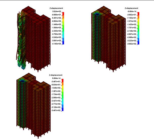
At the second stage of loading using the secondary design scheme, the process of removing the B2 column was simulated by means of reducing the force in this column from 18500 MN to zero during a short time interval tr (see Fig. 3). Analyzing the general picture of deformation and destruction of the structural scheme of the building frame under a specific design load and a special impact caused by the removal of the specified column, it can be seen that while using the viscosity modulus calculated from the data of G. A. Geniev at the stage of dynamic loading [4], there is an intense change in force flows in the structural system and a considerable zone of local failure (Fig. 6a).
31
Russian Journal of Building Construction and Architecture
а |
b |
c
Fig. 6. General view of failure of the structure calculated based
on the experimental data byG. A. Geniev (a), Russian standards (SP (СП) 385.1325800.2018) (b) and based on the experimental data
byN. V. Fedorova and M. D. Medyankin (c)
Deformation of the building frame while using the viscosity modulus obtained in the experiments by N. V. Fedorova and M. D. Medyankin [7, 8] occurred less intensively and in the removal zone of the B2 column, local fracture was not observed (Fig. 6b). A similar pattern of the deformation of the building frame was obtained using the coefficients of increasing the dynamic strength of concrete and reinforcement recommended by the Russian standards for calculating a specific special impact. It should be noted that the viscosity coefficient of concrete, corresponding to the normalized value of the dynamic strength of concrete = 26 seс-1 has a slightly greater value than that the one obtained in the experiments by N. V. Fedorova and M. D. Medyankin (see Table 2).
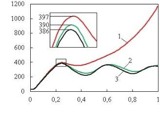
The analysis of the graphs of changes in the deflection of the floor over the removable column depending on the time of dynamic reloading of the structural system td for all the three options (Fig. 7) showed the following. While calculating the option using the viscosity modulus according to the data by G. A. Geniev, the deflection of the floor over the removable column
32
Issue № 4 (52), 2021 |
ISSN 2542-0526 |
continuously increases and at t = 1sec was 1174 mm or the relative deflection f / l = 1/13. In this case, the stabilization of displacement in the area of the removable column does not take place.
Deflection, mm
Fig. 7. Graphs of the change in the deflection of a point above the removed column, depending on time,
calculated based on the experimental data byG. A. Geniev (1),
Russianstandards(SP(СП)385.1325800.2018)(2) and the experimental data byN. V. Fedorova and M. D. Medyankin (3)
Time, sec
The deflection of the slab over the removable column while calculating based on the experimental data by N. V. Fedorova and M. D. Medyankin is considerably less than the one calculated based on the data by G. A. Geniev. On top of that, the structural restructuring of the construction system causes a sudden increase in the deformations in reinforcement and concrete, reaching a peak value after about td = 0.19 sec (dynamic extra loading time) from the moment the column was removed. The maximum deflection of the girder over the removable column in this version was 386 mm or 1/39 of the span, which does not exceed the criterion of a special limiting state according to Russian standards (1/30 of the span) and according to the recommendations provided in foreign literature [10]. Therefore the calculation using the refined viscosity modulus for concrete of various classes makes it possible to calculate the criterion parameters of the structural system in a more rigorous manner.
Conclusions. A computational model, a method for identifying the parameters of the diagrams of the static-dynamic deformation of concrete and reinforcement under a special impact, an algorithm of computational analysis and the results of a nonlinear calculation of the static-dynamic deformation of reinforced concrete frames in out-of-limit states caused by the sudden removal of one of the load-bearing structures are provided.
The results of numerical and experimental studies of frame-bar structural systems of reinforced concrete frames of multi-storey buildings under their two-stage loading –– with a static load to a specific design level and extra loading with a dynamic load caused by a sudden structural restructuring of the structural system when one of the supporting structures is removed from the system showed the need for more rigorous consideration of the physical and
33

Russian Journal of Building Construction and Architecture
mechanical characteristics and deformation diagrams of materials under such loading conditions of structures. The calculated values of such parameters such as the level and mode of loading of the structure, the coefficient of increase in the static-dynamic strength of materials, the time of failure of the removable structural element have a significant (under the studied loading modes up to 19 %) impact on the nonlinear static-dynamic deformation and on their survivability in transcendental states respectively.
The research results can be instrumental in numerical justification of the design of the protection of structural systems of reinforced concrete frames of multi-storey buildings from progressive collapse. By using them, it is not only economical, but also more reliable design solutions that can be obtained.
References
1.Bondarenko V. M., Kolchunov V. I. Ekspozitsiya zhivuchesti zhelezobetona [The exposure of the surviv- abi-lity of reinforced concrete]. Izvestiya vysshikh uchebnykh zavedenii. Stroitel'stvo, 2007, no. 5, pp. 4–– 8.
2.Tuen Vu Ngok. Issledovanie zhivuchesti zhelezobetonnoi konstruktivno nelineinoi ramno-sterzhnevoi sistemy karkasa mnogoetazhnogo zdaniya v dinamicheskoi postanovke [Study of the survivability of a reinforced concrete structurally nonlinear frame-rod system of a multi-storey building frame in a dynamic formulation]. Stroitel'stvo i rekonstruktsiya, 2020, vol. 90, no. 4, pp. 73––84.
3.Geniev G. A. Variant deformatsionnoi teorii plastichnosti betona [Variant of the deformation theory of plas- ti-cityof concrete]. Beton i zhelezobeton, 1969, vol. 2, pp. 18––19.
4.Geniev G. A. Metod opredeleniya dinamicheskikh predelov prochnosti betona [Method of determining the dynamic ultimate strength of concrete]. Beton i zhelezobeton, 1998, vol. 1, pp. 18––19.
5.Kolchunov V. I., Klyueva N. V., Androsova N. B., Bukhtiyarova A. S. Zhivuchest' zdanii i sooruzhenii pri
zaproektnykh vozdeistviyakh [Survivability of buildings during design basis influences]. Moscow, ASV Publ., 2014. 208 p.
6.Kodysh E. N. Proektirovanie zashchityzdanii i sooruzhenii ot progressiruyushchego obrusheniya s uchetom vozniknoveniya osobogo predel'nogo sostoyaniya [The protection design of buildings and structures against progressive collapse, given the emergence of limit state]. Promyshlennoe i grazhdanskoe stroitel'stvo, 2018, vol. 10, pp. 95––101.
7.Fedorova N. V., Medyankin M. D., Bushova O. B. Eksperimental'noe opredelenie parametrov statikodinamicheskogo deformirovaniya betona pri rezhimnom nagruzhenii [Experimental determination of the parameters of static and dynamic deformation of concrete under loading modal]. Stroitel'stvo i rekonstruktsiya, 2020, no. 3, pp. 72––81.
8.Fedorova N. V., Medyankin M. D., Bushova O. B. Opredelenie parametrov statiko-dinamicheskogo deformirovaniya betona [Determination of the parameters of static and dynamic deformation of concrete].
Promyshlennoe i grazhdanskoe stroitel'stvo, 2020, no. 1, pp. 4––11.
9.Fedorova N. V., Tuen Vu Ngok, Yakovenko I. A. Kriterii prochnosti ploskonapryazhennogo zhelezobetonnogo elementa pri osobom vozdeistvii [Criterion of strength of a flat-stressed reinforced concrete element under special impact]. Vestnik MGSU, 2020, vol. 15, no. 11, pp. 1513––1522.
10.Alogla K., Weekes L., Augusthus-Nelson L. A new mitigation scheme to resist progressive collapse of RC structures. Construction and Building Materials, 2016, vol. 125, pp. 533––545.
11.Fedorova N., Kolchunov V., Tuyen V. N., Dinh Quoc P., Medyankin M. The dynamic effect in a structural adjustment of reinforced concrete structural system. IOP Conference Series: Materials Science and Engineering, 2020, vol. 869, p. 052078.
34
Issue № 4 (52), 2021 |
ISSN 2542-0526 |
12.Fedorova N. V., Vu N. T., Iliushchenko T. A. Dynamic additional loading of the frame of a multi-story building after the failure of one of the structures. IOP Conference Series: Materials Science and Engineering, 2020, vol. 896, no. 1, p. 012040.
13.Fedorova N., Kolchunov V., N. Tuyen Vu, Iliushchenko T. Determination of stiffness parameters of reinforced concrete structures using the decomposition method for calculating their survivability. IOP Conference Series: Materials Science and Engineering, 2021, vol. 1030, no. 1, p. 012078. doi: 10.1088/1757899X/1030/1/012078.
14.Fialko S., Kabantsev O., Perelmuter A. Elasto-plastic progressive collapse analysis based on the integration
of the equations of motion. Magazine of Civil Engineering, 2021, vol. 102, no. 2, pp. 10214––10214. doi: 10.34910/MCE.102.14.
15.GSA. Alternate path analysis and design guidelines for progressive collapse resistance, Washington, D.C., 2016. 203 p.
16.Hallquist J. O. LS-DYNA Theorymanual. Livermore Software TechnologyCorporation (LSTC). Livermore (USA), 2006. 1576 p.
17.Izzuddin B. A. Mitigation of progressive collapse in multi-storey buildings. Advances in Structural Engineering, 2012, vol. 15, no. 9, pp. 1505––1520. doi: 10.1260/1369-4332.15.9.1505.
18.Qian K., Weng Y. H., Li B. Impact of two columns missing on dynamic response of RC flat slab structures. Engineering Structures, 2018, vol. 177, pp. 598––615. doi: 10.1016/J.ENGSTRUCT.2018.10.011.
19.Tamrazyan A. Reduce the impact of dynamic strength of concrete under fire conditions on bearing capacity of reinforced concrete columns. Applied Mechanics and Materials. Trans Tech Publications Ltd, 2014, vol. 475––476, pp. 1563––1566. doi: 10.4028/www.scientific.net/AMM.475-476.1563.
20.UFC 4-023-03. Design of Buildings to Resist Progressive Collapse, Department of Defense USA, 2010. 176 p.
35

Russian Journal of Building Construction and Architecture
HEAT AND GAS SUPPLY, VENTILATION,
AIR CONDITIONING, GAS SUPPLY AND ILLUMINATION
DOI 10.36622/VSTU.2021.52.4.003
UDC 697.33:697.34
A. A. Chuikina 1, M. Ya. Panov 2, S. N. Kuznetsov 3
DEVELOPMENT OF A METHODOLOGY
FOR DETERMINING THE BEST OPTION FOR THE ROUTE
OF THE HEAT NETWORK AT THE INITIAL DESIGN STAGE
Voronezh State Technical University 1, 2, 3
Russia, Voronezh
1Ph. D. student of the Dept. of Heat Supply and Oil and Gas Business, e-mail: teplosnab_kaf@vgasu.vrn.ru
2D. Sc. in Engineering, Prof. of the Dept. of Heat and Gas Supply and Oil and Gas Business, tel.: (473)271-53-21
3D. Sc. in Engineering, Assoc. Prof., Prof. of the Dept. of Heat and Gas Supply and Oil and Gas Business,
tel.: (473)271-53-21, e-mail: teplosnab_kaf@vgasu.vrn.ru
Statement of the problem. Choosing the best option for the route of the thermal network at the initial stage of design is a complex multifactorial task, in addition, due to the lack of a number of necessary design calculations, its solution is accompanied by a limited set of initial data. Thus, it becomes relevant to develop a new methodology for designing the optimal route of the heat supply system consideringthe qualitative and quantitative characteristics of the discussed object.
Results. A mathematical model of a generalized additive vector optimality criterion has been developed, taking into account the material consumption of the heat network, its reliability, construction time, annual thermal losses, heat turnover and temperature dispersion at the consumer. A method is proposed for determining the best option for the route of a thermal network at the initial design stage by jointly solving the optimization problem using vector optimization and matrix generalization methods. The expediency of the joint application of the methods of pairwise comparison and vector optimization in solving the problem under consideration isnoted.
Conclusions. An important characteristic of the developed mathematical model of the generalized criterion is the possibility of obtaining a more accurate solution to the optimization problem under consideration with an uneven distribution of the heat load by means of a biased estimate of the temperature variance among consumers. A combination of the methods of matrix generalization, pairwise comparison and vector optimization can improve the accuracy of the calculation while solving the optimization problem of choosing the best route of the thermal network.
Keywords: thermal networks, normalized optimality criteria, the best route option, multi-criteria optimization, pairwise comparison.
Introduction. In [7, 11, 12] it was noted that the choice of the best one or a few equivalent options for tracing the heating network is a special case of a multi-criteria optimization problem. The solution to this problem involves having to identity a certain number of criteria for comparing the options under consideration. An error in the selection of these criteria might cause a wrong solution. Through the course of research, the results of which were presented in [11,
© Chuikina A. A., Panov M. Ya., Kuznetsov S. N., 2021
36
Issue № 4 (52), 2021 |
ISSN 2542-0526 |
13, 14], the use of enlarged parameters of the material characteristic M, the actual heat turnover Zf, construction time Tstr, annual heat losses Qt.p. was justified, reliability Rsyst and temperature dispersion at the consumer σ as comparison criteria. This makes it possible to obtain a more accurate solution of the optimization problem under discussion at the initial design stage when there is lack of initial data for the calculation.
There are presently lots of methods for solving optimization problems. Hence, in [7] the method of the generalized additive vector criterion of optimality is examined, the method based on the matrix generalization in [12]. The disadvantage of the first method is a high degree of subjectivity of the resulting solution associated with assigning weights to the selected particular optimality criteria, which is commonly performed by means of expert assessments. The disadvantage of the second method is that when it is applied (in the case of a large number of comparison criteria), it is only possible to obtain a limited set of options without highlighting the best one. Therefore it becomes urgent to develop a methodology for choosing the best option for a heating network route having none of the above disadvantages.
1. Normalizing particular criteria for choosing the best solution. As the aggregated parameters selected as optimality criteria have different dimensions, and their values can equal one, dozens, hundreds, and even thousands, for the correct application of the criteria it is essential to normalize and reduce them to a dimensionless form. There are a few ways to do this [10], we are going to consider the most common ones.
Directive value of the particular criteria. This value is recommended to be used as a normalizing divisor, it is set by an expert. In this case, the transformed criterion will be given by the formula
f |
|
x |
Fi x |
, |
(1) |
|
i |
Fнорм x |
|||||
|
|
|
|
|||
|
|
|
i |
|
|
where Fi(x) is the optimality criterion prior to rationing; Fiнорм(x) is the i-th normalized divider; fi(x) is the normalized value of the optimality criterion.
This method can be used, e.g., for the indicator of the actual heat turnover. The theoretical turnover ZT, which is an indicator of the inevitable transit of thermal energy and the minimum possible value, can serve as a standardized divider. With the same location of the source and consumers for all schemes, this indicator will be the same, which is convenient while standardizing the criterion. The main disadvantage of this option is the assumption that the specified value of the divisor will be exemplary, i.e., the choice of this value is not always possible, particularly in problems like the one we are dealing with.
37

Russian Journal of Building Construction and Architecture
Maximum value of the particular criteria. As a normalizing divisor, it is suggested that the maximum value of the value that is achieved in the field of existence of design solutions is used. Then the transformed criterion will be given by the formula
f |
|
x |
Fi x |
, |
(2) |
|
i |
Fmax x |
|||||
|
|
|
|
where Fmax (x) is the maximum value of the optimality criterion. A similar option was considered in [7] for the convenience of presenting the criteria in graphical form.
Difference between the maximum and minimum values of the particular criterion in the area of compromise. Then the transformed optimality criterion will be defined as
F x Fmax x |
|
|
fi x 1 Fmini x Fmax x |
, |
(3) |
where Fmin(x) is the minimum value of a particular criterion of optimality. In [9], this method is called the most convenient one.
The choice of one of the methods is daunting and affects the outcome of the calculation. E.g., the first method is less suitable for the reliability indicator, as it is difficult to identify e the required reliability in each specific case. Thus it is advisable to apply the third method. As at the moment it is generally accepted that, depending on the reliability indicator, heat supply systems are divided into several groups: systems with a high reliability (or highly reliable ones) –– Rsyst is more than 0.9; reliable systems –– Rsyst is from 0.89 to 0.75; unreliable systems –– Rsyst is from 0.5 to 0.75; unreliable systems –– Rsyst is less than 0.5, then 0.5 can be taken as the minimum value, and 0.9 as the maximum one. It is also advisable that dependence (3) is applied for the remaining particular criteria of optimality of the problem. As
Fmax(x) it is essential to take the maximum value of the particular criterion in the area of the discussed solutions, and as Fmin (x) the minimum value.
2. Developing a methodology for choosing the best option for a heating network route.
As noted above, there are lots of methods for addressing optimization problems, their choice can have a major influence on the outcome. The models previously discussed in [7, 11, 12] designed based on the method of folding particular criteria, relied on the condition of the availability of qualitative information about a set of the particular criteria [1, 2] in the form of a series of priorities of one criterion over another.
There are lots of ways to account for the importance of the particular criteria, e.g., [1, 12]:
a)the method of sequential optimization of the criteria considering rigid prioritization which is characterized by the fact that the minimization of the n-th criterion is per-
38
Issue № 4 (52), 2021 |
ISSN 2542-0526 |
formed only after obtaining the minimum value of all the previous (n – 1)-th criteria. The disadvantage of this method is the possibility of degeneration into a point of the region of satisfactory solutions R;
b) the method of successive concessions is a modification of the method of successive optimization: at each optimization step, a concession Fn – 1 is sequentially introduced, which characterizes the permissible deviation of the (n – 1)-th criterion;
c)the method for identifying the main criterion is search for the minimum of the most important or main optimality criterion F1(x) is performed and the values of other criteria are F2(x), F3(x), etc. must not exceed certain thresholds:
min F x , |
(4) |
||||
1 |
|
|
|
||
x R' |
|
||||
R' R R0;R0 x |
|
gi x gi0,i |
|
; |
(5) |
|
2,N |
||||
d)the method of guaranteed result is when the worst criterion is modified to fit to the le-vel of the main criteria, as a result, this task is equivalent to the one solved using concessions;
e)the method of the ideal point is when extra information is presented in the form of an ideal solution, and the initial problem is solved by constructing a generalized criterion and a one-criterion optimization problem;
f)the method of equality of the particular criteria is when there is an equivalence of the importance of the criteria:
min F x , |
(6) |
k |
|
x R |
|
R1(x) R2(x) ... Rk(x); |
(7) |
g)the method of folding the vector criterion is the most common one for the problem. The unification of particular criteria into one integral criterion is performed. In this case, the importance of the criterion is considered due to the functionS:
min x R S p,F x , |
(8) |
where р is the weight of the criteria.
In this method, the folding of the generalized criterion can be performed by means of various methods, depending on which their mathematical notation changes, e.g.:
the logical criterion is written in the form
S |
p,F x max piFi x ; |
(9) |
max |
1 i N |
|
39