

Учебное пособие 2254
.pdfRussian Journal of Building Construction and Architecture
DOI10.36622/VSTU.2021.52.4.002 UDC624.012.45
N. V. Fedorova 1, Vu Ngoc Tuyen 2, M. D. Medyankin 3
ANALYSIS OF NONLINEAR STATIC-DYNAMIC DEFORMATION
OF REINFORCED CONCRETE FRAMES IN OUT-OF-LIMIT STATES *
Moscow State University of Civil Engineering 1, 2, 3
Russia, Moscow
1D. Sc. in Engineering, Prof. of the Dept. of Architectural and Construction Design, e-mail: fenavit@mail.ru
2PhD in Engineering, lecturer of the Dept. of Architectural and Construction Design,
e-mail: ngoctuyennd91@gmail.com
3 PhD student of the Dept. of Reinforced Concrete and Masonry Structures, e-mail: 412125453@mail.ru
Statement of the problem. The article presents a computational model, an algorithm for computational analysis and the results of calculating the nonlinear static-dynamic deformation of reinforced concrete frames in out-of-limit states caused by the sudden removal of one of the supporting structures.
Results. To design a numerical model of the static-dynamic loading mode of a structural system, the LS-DYNA software package was used that makes use of a detailed 3D model implementing an explicit finite element method. During the computational analysis, the physical and mechanical characteristics of the deformation of materials were taken in three variants: those obtained based on the experimental data by G. A. Geniev, the experimental data by N. V. Fedorova and M. D. Medyankin under the static-dynamic uniaxial testing mode of a limited number of standard samples of prisms and according to the Russian standards SP (СП) 385.1325800.2018.
Conclusions. Numerical analysis of the static-dynamic deformation of thereinforced concrete framerod system of a multi-storey building has established that the differentiated accounting of the quantitative value of the concrete viscosity modulus and, accordingly, the time and level of static-dynamic loading of the structure allows one to identify the criteria for the special limit state of the elements of reinforced concretestructural systems of buildingsand structuresin a morerigid manner.
Keywords: reinforced concrete, progressive collapse, survivability, special limit state, nonlinear dynamic analysis, static-dynamic deformation.
Introduction. As problems aimed at studying the problem of survivability of buildings and structures and reducing the number of accidents during the operation of building structures need to be addressed, a number of new associated scientific issues have emerged calling for further examination both for theoretical substantiation of individual provisions and their practical application in the calculation of structures [1, 5, 17].One of them is to identify the stressstrain of reinforced concrete structural systems imme-diately following dynamic loading caused by failure of individual elements considering the specific features and time of extra loading of structural system elements under the discussed impact [6, 14, 19].
© Fedorova N. V., Vu Ngoc Tuyen, Medyankin M. D., 2021
*This research was supported by Project # 3.1.7.1 within the 2021-2023 Plan of Fundamental Research of the Russian Academy of Architecture and Civil Engineering and Ministry of Civil Engineering and Public Utilities of the Russian Federation. The experimental studies have been carried out using the facilities of the Collective Research Center named after Professor Yu.M. Borisov, Voronezh State Technical University, which is partly supported by the Ministry of Science and Education of the Russian Federation, Project No 075-15-2021-662.
20
Issue № 4 (52), 2021 |
ISSN 2542-0526 |
While calculating reinforced concrete structures for progressive collapse from such an impact, static or dynamic diagrams of deformation of materials have been employed so far, which does not correspond to the discussed loading modes. Therefore this paper presents the results of the analysis of nonlinear deformation of reinforced concrete frames in out-of-limit states caused by a special emergency impact with the use of the calculated parameters of the experimentally obtained diagrams ofthe static-dynamic deformation of concrete.
1. Theoretical justification. Back in the 1960s, in the works by Prof. G. A. Geniev, according to experimental studies of lowand middle-class concrete and their analysis, a deformation theory of plasticity of concrete and reinforced concrete in a complex stressed state was deve-loped [3].
The major physical dependence of the version of the deformation theory of concrete plasticity applied can be represented as follows:
|
|
|
|
|
|
|
|
|
|
|
Г |
|
|
|
|
|
|
|
|
|
T G0 1 |
|
|
Г , |
(1) |
||
|
|
|
|
|
|
|
|||||||
|
|
|
|
|
|
|
|
|
|
2Гs |
|
||
where T 1/ |
|
|
|
|
|
|
|
|
|
||||
|
1 2 2 |
2 |
3 2 |
3 1 2 |
is the intensity of tangential stresses, |
||||||||
6 |
|||||||||||||
|
|
|
|
|
|
|
|
|
|||||
G0 is the initial shear modulus, |
Г |
|
|
|
|
1 2 2 |
2 3 2 3 1 2 |
is the intensity |
|||||
|
2/3 |
||||||||||||
of shear deformation, Гs is the limited intensity of shear deformation. Due to its versatility,
flexibility, and ease of use, this deformation theory has been applied in solving a number of
practical problems of calculating complexly stressed reinforced concrete structures [9].
Developing this theory while solving dynamic problems, G. A. Geniev [4] set forth a relatively
simple and sufficiently rigorous for engineering calculations rheological mathematical model for
identifying the dynamic strengthofconcreteunder theaction ofexternal dynamic loads lasting no
longer than tenths and hundredths of a second. The model consists ofparallel-connected elements
Aand B. The first element A is described bythedeformationtheoryofconcreteplasticity(1). The
viscous Newtonian element B causes an increase in the dynamic strength of concrete and is char-
acterized byaconstant K which is the modulusofviscousresistance. This model leadsto thesolution of the nonlinear Riccati equation that enables an analytical relationship to established be-
tweenthedynamicactiontimetd and thecorresponding dynamic strength limit |
d |
Td /T : |
||||||||||
|
|
|
|
|
|
|
|
|
|
|
b |
|
|
|
|
|
|
|
|
|
|
|
|
|
|
|
|
2 |
|
arcсtg bd |
1 |
|
|
|||||
t |
d |
|
|
|
|
|
|
|
. |
|
|
|
|
|
|
|
|
|
(2) |
||||||
bd 1 |
|
|||||||||||
|
|
|
|
|
|
|
||||||
21
Russian Journal of Building Construction and Architecture
Dependence (2) includes a parameter whose value is identified experimentally for a particular class of concrete –– from a limited number of uniaxial dynamic tests. It should be noted that according to G. A. Geniev, the average value of this parameter of the experimental data available at that time for heavy low-grade concretes under dynamic loading was approximately taken equal to 102 314 с 1. However, for the above problems of calculating structures for progressive collapse, this parameter of concrete deformation does not completely reflect the mode in question: static loading of structures with an operational load followed by dynamic extra loading by an emergency effect. For such a loading mode of high-strength concretes and particularly high-strength concretes, there are no experimental data for identifying the viscosity modulus under dynamic as well as static-dynamic loading conditions.
At the Research Scientific University Moscow State University of Civil Engineering under the supervision of Prof. N. V. Fedorova a new method of testing prototypes of prisms made of concrete of different strengths under such loading conditions was developed and tests of staticdynamic deformation of ordinary and high-strength concrete were performed [7]. The values of
the viscous resistance modulus of concrete are experimentally identified К as well as a pa-
rameter at different levels of static loading of concrete. Based on the obtained experimental data, an analytical design model was designed for identifying the dynamic strength ofconcrete depend-
|
s |
|
|
|
|
and timeofextradynamic loading[8]: |
|||||||
ing onthe levelofits static loading Tst /Tst , |
|
0,1 |
|||||||||||
|
|
|
|
|
|
|
|
|
|
|
|
|
|
|
|
|
arcсtg |
st d |
|
1 |
|
||||||
|
2 |
|
b |
|
|
|
|||||||
|
|
|
|
|
|||||||||
td |
|
|
|
|
|
|
1 |
|
. |
(3) |
|||
|
|
|
|
|
|
|
|
|
|
||||
|
bst d |
|
|
|
|||||||||
|
|
|
1 |
|
|
|
|||||||
|
|
|
|
|
|
|
|
|
|
|
|
||
1
The developed computational model is based on a working hypothesis about the affinity-like behavior of concrete deformation diagrams under static and dynamic loading. The calculation results for the suggested version of the deformation model are in good agreement with the results of experimental studies of prototypes of concrete prisms [8].
The dynamic calculation of buildings and structures for progressive collapse, described in some research papers [2, 18], is considered the most challenging but also the most accurate method for assessing the stress-strain of a structure under the static-dynamic mode of its loading. The major difficulties of such a calculation are associated with the rapid deformation and failure of reinforced concrete structures. The authors make use of software packages that implement the finite element method using an explicit integration scheme for the equation of
22
Issue № 4 (52), 2021 |
ISSN 2542-0526 |
dynamics. However, such programs use dynamic methods that do not allow problems under static loading of the structure to be solved. The disadvantage of the explicit integration scheme while modeling the first stage of static loading of the process under study is that the «slow» static load is perceived by the system as a shock, which does not correspond to the physics of the above process.
To eliminate this disadvantage as well as undesirable vibrations of the investigated structural system under the influence of a static operating load, [2] describes the mode of static-dynamic loading of the structural system using the LS-DYNA software package. In this mode, during a sufficiently long period of time from t = 0 to t1, constant and temporary long-term loads were applied and gradually increased to their specified values. Then, the structural system was kept under this load for t = t2 – t1 to stabilize the stress state in it under the applied loads. This modeling approach is fairly simple and straightforward, but there are downsides associated with the volume of the calculation and the limited resource of the computer due to the need for a significant investment of time for integrating the equations as well as due to the impossibility of ensuring the quasi-static state of the structural system at the first stage of its static loading. On top of that, the use in [2] of a constant value of the coefficient of dynamic increase in the strength of materials over the entire range of two-stage static-dynamic loading leads to a rather rough estimate of the stress-strain of the structure under the discussed twostage loading mode.
Considering the above new scientific achievements of domestic and foreign scientists in the field of concrete and reinforced concrete mechanics, it appears essential to make use of refined experimental parameters of concrete deformation under the considered static-dynamic loading regime in the problems of calculating buildings and structures for progressive collapse. Thus the goal of this work is to analyze nonlinear static-dynamic deformation of reinforced concrete frames in extreme states by means of actual experimental diagrams of staticdynamic concrete deformation. As an example, the results of a numerical study of a threedimensional frame of a monolithic reinforced concrete building, subjected to a special effect in the form of a sudden removal of one of the load-bearing columns of the first floor considering the specific features of static-dynamic deformation of concrete are presented. To eliminate the noted downsides of the design analysis of structures under the discussed two-stage loading mode, this paper presents a new more universal technique for modeling the process of static-dynamic loading of a structure using the dynamic relaxation method and two-stage design models.
23
Russian Journal of Building Construction and Architecture
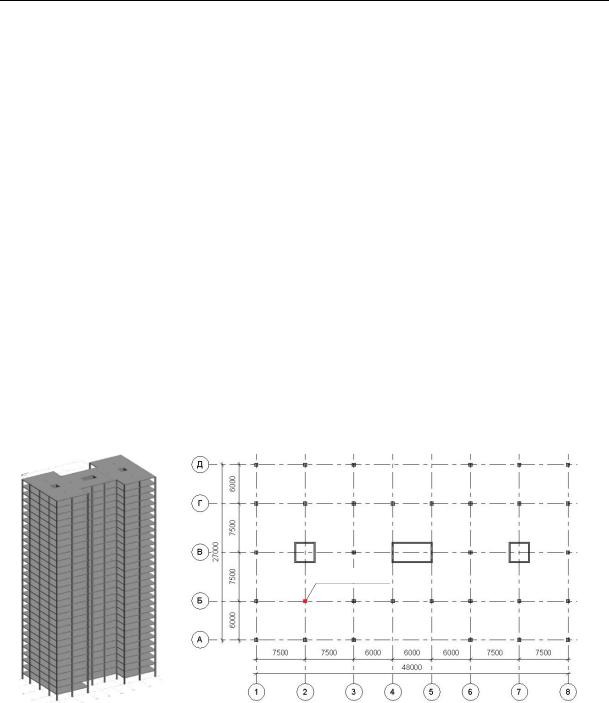
2. Designing a computational model. To implement the suggested technique, the frame of a reinforced concrete monolithic 30-storey residential building is discussed which has a cruciform shape in plan with overall dimensions of 27.0 × 48.0 m (Fig. 1a). The height of the floor is 3 m. The height of the building is 90 m. The columns of the frame have a square section of 750 × 750 mm. For the perception of horizontal loads, monolithic reinforced concrete diaphragms of stiffness with a thickness of 200 mm are used. The floor slab, 150 mm thick, is reinforced with a cross system of stiffeners with a cross-sectional area of 150 × 300 mm located at the bottom of the slab. External walls and internal partitions are made of lightweight materials and supported by floor slabs. The safety factor in the design scheme does not include building elements that are not load-bearing during normal operation. The building rests on a rigid, non-deformable foundation. While calculating for progressive collapse, a variant of the secondary design scheme was considered (in the terminology of the Russian norm SP (СП) 385.1325800.2018) for scenarios of special impact: the inner column B2 on the first floor was removed from the design model (Fig.1b).
аb
Removable column
Fig. 1. Construction scheme (а)and the plan of the first floor (b) of reinforced concrete building frame
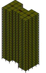
Numerical studies of the operation of structures with local damage were performed in a nonlinear dynamic formulation using the LS-Dyna software complex having numerical stability and a wide variety of constitutive models. The maximum size of the model elements 1 m × 1 m was chosen by the authors due to a compromise between the optimal calculation accuracy and the number of computational operations. The constructed model of the building in the LSPrepost preprocessor, consisting of 52.200 finite elements, is shown in Fig. 2.
24
Issue № 4 (52), 2021 |
ISSN 2542-0526 |
Fig. 2. General view of the finite element model of the building frame
Reinforced concrete columns and girders are modeled by means of BEAM161 bar elements with the Hughes-Liu formulation. Floor slabs and longitudinal stiffening diaphragms are modeled by means of 4-node shell elements (SHELL163) [16]. To address the problem of static-dynamic deformation of reinforced concrete frames in out-of-limit states, an explicit finite element method was employed with the possibility of constructing a Lagrangian mesh. Such a model has a sufficient accuracy at lower computational costs than a volumetric element model and can be beneficially used for modeling a multi-storey skeleton building.
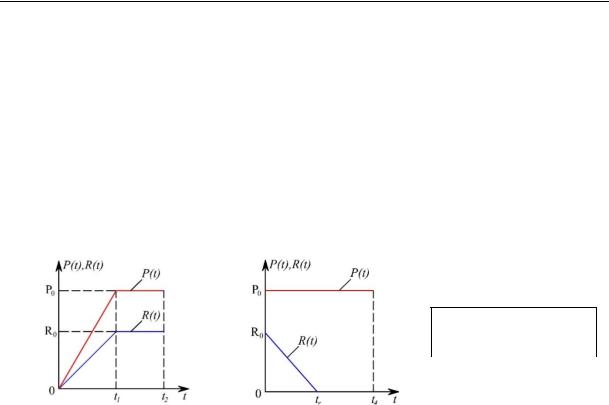
3. Considered loads, influences and mode of stress. Depending on the static-dynamic loading regime of the structural system, the calculation for progressive collapse is performed in stages. At the initial stage, the stress-strain of the building frame structures under normal operating conditions is identified for the primary design scheme. At the same time, in compliance with SP (СП) 286.1325800.2016, the following design loads are accepted: constant loads from the dead weight of structures (25 KN/m3) and the total temporary long-term load (8 KN/m2). The reliability factor for load and responsibility is taken equal to one. During t = 0 to t1 = 0.5 seconds, constant and temporary continuous loads P(t) were applied and increased to operational values P0 using the * LOAD_BODY and * LOAD_SHELL_SET cards (Fig. 3a). The sloped section of the load curve is introduced for ensuring the stability of the integration process and provides for a step-by-step application of the load from zero to the specified design values. The internal force R(t) acting in the removed column also increased from zero to the full value of R0 over the same period of time. At the same time, in order to exclude possible undesirable dynamic fluctuations due to a sharp application of the operational load in an explicit setting, the dynamic relaxation method is used (* CONTROL_DYNAMIC_RELAXATION map). The essence of this method is that at each integration step, a decrease in the nodal velocities
25
Russian Journal of Building Construction and Architecture
of finite elements of the structure is ensured by multiplying by a certain coefficient below one (the DRFCTR coefficient and by default it was taken equal to 0.995). Hence at the initial stage, a «pseudo-static» design calculation is conducted.
Then the system was kept under the described load for the time t = t2 – t1 to achieve the criterion of convergence of the calculation on dynamic relaxation when the amount of kinetic energy remaining in the system at the final moment of calculation (t2) is less than 0.001 (Fig. 3a). Therefore the stress-strain is achieved in the elements of the structural state of the column shutdown, approximately its static loading.
а |
b |
Loading time, sec
t1 |
t2 |
tr |
t4 |
0.5 |
1 |
0.01 |
1 |
Fig. 3. Loading mode of the operational load P(t) and projected impact R(t) in the original (а) and secondary(b) calculation scheme
At the second stage of the analysis, the stress-strain of the structures is identified based on the secondary design scheme obtained from the original one by excluding the load-bearing structural element. In this case, the results of the calculation based on the original design scheme using the dynamic relaxation method are the initial conditions for the secondary design scheme. To simulate the instantaneous removal of the column of the first floor B2, the force
R(t) acting in it, which was previously identified by means of the calculation based on the original design scheme, is forced to zero during a certain short time interval tr, called the column failure time (Fig. 3b). Through the course of the dynamic calculations, the column failure time was taken as tr < 0.01T, where T is the time corresponding to the first natural vibration frequency of the damaged structure. This approach is implemented using the *LOAD_REMOVE_PART map. The service load in the secondary design was kept constant for the time period t4 > tr. The numerical values of t1, t2, tr, t4 are presented in the table in Fig. 1b. Hence in the second stage of modeling, the external load acting on the structure and the time-varying forces in the removable structural column are considered.
4. Physical and mechanical characteristics and deformation diagrams of materials. In the computational analysis, the physical and mechanical characteristics of the deformation of materials were taken in three versions: those obtained according to the experimental data by
26
Issue № 4 (52), 2021 |
ISSN 2542-0526 |
G. A. Geniev, according to the experimental data by N. V. Fedorova and M. D. Medyankin according to the Russian standards SP (СП) 385.1325800.2018. All the load-bearing structural elements of the calculated building frame are designed from B70 concrete and reinforced with A500 class working reinforcement. In the structures of the girders, symmetric reinforcement is adopted to protect the building from progressive collapse following the removal of the load-bearing column. The material model *MAT_CONCRETE_EC2 was employed which was developed specifically to describe the behavior of reinforced concrete structures using beam and shell FE. The strength characteristics of materials are taken equal to their standard values. The input parameters of static deformation of materials required for quasi-static analysis at the first stage of loading according to the primary design scheme are presented in Table 1.
Таble 1
Input parameters of static deformation of materials for pseudostatic analysis according to the original design scheme
|
|
Denoted according |
Denoted |
Input values in LS Dyna |
|
|
|
to SP (СП) 63 |
in LS Dyna |
||
|
|
|
|||
|
Density |
t/mm3 |
RO |
2.5 10 9 |
|
|
Compressive strength design value |
Rb,ser (МPа) |
FC |
50 |
|
|
|
|
|
|
|
V70 |
Calculated tensile strength |
Rbt,ser (МPа) |
FT |
3 |
|
Ultimate tensile strain |
bt2 |
ECUTEN |
0.00015 |
||
Concrete |
|||||
Poisson's ratio |
b,P |
PRT36 |
0.2 |
||
|
Initial elasticitymodulus of concrete |
Eb (МPа) |
ET36 |
4.1 104 |
|
|
|
|
|
|
|
|
Specific compression strain |
b0 |
EC1_6 |
–0.002 |
|
|
b2 |
ECUT36, |
|
||
|
|
ECSP69 |
–0,0035 |
||
|
|
|
|||
|
Elasticitymodulus |
Es (МPа) |
YMREINF |
2 105 |
|
|
Poisson's ratio |
s,P |
PRRINF |
0.3 |
|
А500 |
Calculated tensile strength |
Rs,ser (МPа) |
SUREINF |
500 |
|
|
|
|
|
||
Specific deformation |
s2 |
Via *CURVE |
0.033 |
||
Reinforcement |
|
|
maps |
|
|
|
|
|
Columns: 0.672 %; |
||
|
|
|
|
||
|
Reinforcement percentage |
s,x |
FRACRX |
Crossbars, floor slabs |
|
|
alonghte local axis X |
and stiffening |
|||
|
|
|
|||
|
|
|
|
diaphragms:0.704 % |
|
|
|
|
|
Columns: 0.672 %; |
|
|
Reinforcement percentage |
s,y |
FRACRY |
Crossbars, floor slabs |
|
|
alonghte local axis Y |
and stiffening |
|||
|
|
|
|
diaphragms: 0.704 % |
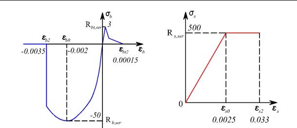
A diagram of the static deformation of concrete was constructed according to the input parameters (Fig. 4a). The behavior of reinforcing steel is presented using a piecewise linear model of the Prantl type (Fig. 4b).
27
Russian Journal of Building Construction and Architecture
а |
b |
Fig. 4. State diagrams of materials under quasi-static loading according tothe primarydesign scheme of: a –– concrete; b —reinforcement
While calculating, the limiting values of maximum deformations in compressed concrete were taken as a criterion for the transcendental state of reinforced concrete elements of a structural system b2 = –0.0035 and in stretched reinforcement s2 = 0.033. If this criterion was not met in a specific element of the structural system, it was excluded from work.
The analytical dependence (3), according to which the coefficient of increase in the staticdynamic ultimate strength of concrete is calculated for the calculation according to the secondary design scheme, includes the following parameters:
The analytical dependence (3), according to which the coefficient of increase in the staticdynamic ultimate strength of concrete bst d is calculated for the calculation according to the secondary design scheme, includes the following parameters:
( ) is the the relative level of static loading of reinforced concrete elements of the structural system identified by comparing the operational load on the structure with the ultimate load that the structure can accept (the load-bearing capacity of the structure). In the present study, the relative level of static loading ( ) is taken equal 0.3;
td is the time of dynamic reloading, i.e. the time when during the transition of a con-
structively nonlinear system from n-times statically indeterminate to (n–1)-times statically indeterminate, an increment ofstresses and strains takes place in concrete and reinforcement of elements from a sudden redistribution of power flows. This parameter can be identified in a simplified way using the well-known equation of motion of a substructure in the form of a reinforced concrete beam with one degree of freedom which simulatesthe zoneof local failure[11, 12]:
28

Issue № 4 (52), 2021 ISSN 2542-0526
|
|
t |
|
1 2 2 |
|
|
t |
|
|
2 |
|
|
|
t |
|
|
|
|
|
||||||||||||||||
ust |
0 |
|
|
|
|
|
|
|
|
|
|
|
e |
|
n |
|
sin Dt |
|
|
|
|
1 e |
|
|
n |
cos Dt at |
0 t tr , |
|
|||||||
t |
r |
|
|
t |
|
D |
|
|
|
t |
|
n |
|
|
|
||||||||||||||||||||
|
|
|
|
|
|
|
r |
|
|
|
|
|
|
|
|
|
r |
|
|
|
|
|
|
|
|
|
|
|
|
|
|||||
|
|
|
|
|
2 |
|
|
|
|
t |
|
|
|
|
t t |
|
|
|
|
|
|
|
|
|
|
||||||||||
|
|
|
|
|
e |
|
|
|
|
|
D |
|
|
|
|
|
|||||||||||||||||||
u(t) |
|
1 |
|
|
|
|
|
|
|
n |
cos t e |
|
n |
|
|
r |
cos |
t t |
|
|
(4) |
||||||||||||||
|
t |
|
|
|
|
|
|
|
|||||||||||||||||||||||||||
|
|
|
|
|
|
|
|
|
|
|
|
D |
|
|
|
|
|
|
|
|
|
|
r |
|
|||||||||||
0 |
|
|
|
r |
n |
|
|
|
|
|
|
|
|
|
|
|
|
|
|
|
|
|
|
|
|
|
|
|
|
|
|||||
ust |
|
|
1 2 |
2 |
|
|
|
|
|
|
|
|
|
|
|
|
|
|
|
|
|
|
|
|
|
at t tr , |
|
||||||||
|
|
|
|
|
e nt sin Dt e n t tr sin D t tr |
|
|
|
|||||||||||||||||||||||||||
|
|
t |
|
|
|
|
|
|
|||||||||||||||||||||||||||
|
|
|
|
|
|
|
|
|
|
|
|
|
|
|
|
|
|
|
|
|
|
|
|
|
|
|
|
|
|
|
|||||
|
|
|
|
|
r |
|
D |
|
|
|
|
|
|
|
|
|
|
|
|
|
|
|
|
|
|
|
|
|
|
|
|
|
|||
where tr is the time of failure of the column; D n |
|
|
|
is the frequency of eigenfre- |
|||||||||||||||||||||||||||||||
|
1 2 |
||||||||||||||||||||||||||||||||||
quencies of a substructure considering the energy dissipation; |
ust 0 P0 / m n2 |
is a static |
|||||||||||||||||||||||||||||||||
deflection of the substructure; c / 2m n |
is the damping coefficient. |
|
|
||||||||||||||||||||||||||||||||
Analyzing the equation (4), it is easy to see that the maximum time of dynamic extra loading
td is always longer than |
tr . Therefore for identifying this time let us look at the speed of the |
|||||||||||||||||||
discussed substructure only for the case t |
|
> tr : |
|
|
|
|
||||||||||||||
|
|
|
d |
|
|
|
|
2 |
|
nt |
|
|
|
n t tr |
|
|
|
|||
u |
(t) |
|
[ ust 0 |
{1 |
|
|
e |
|
|
cos Dt e |
|
cos D |
t tr |
|
||||||
dt |
t |
|
|
|
|
|
||||||||||||||
|
|
|
|
|
|
|
|
r |
n |
|
|
|
|
|
|
|
|
. |
(5) |
|
|
|
1 2 2 |
e |
|
|
|
|
|
|
|
t t |
|
sin D t tr }] |
|||||||
|
t |
sin Dt |
e |
|
|
|||||||||||||||
|
|
|
n |
|
n |
|
r |
|
|
|
||||||||||
tr D |
|
|
|
|
|
|
||||||||||||||
|
|
|
|
|
|
|
|
|
|
|
|
|
|
|
|
|
|
|
||
The dynamic deflection of the substructure reaches its maximum value when its speed drops down to zero.
|
(6) |
u(t) 0. |
Based on the solution of equation (6), a formula is obtained for identifying the time of dynamic extra loading of the substructure considering the time of failure of the column:
td |
|
tr |
|
T |
, |
(7) |
|
|
|||||
|
2 |
2 |
|
|
||
where T 2 / n is the oscillation period of the substructure which is identified using the method described in [13]. The results of calculations according to the above formula are shown in Table 2.
Dependence (3) includes another important parameter associated with the time of dynamic action which is essential for the coefficient of increase in static-dynamic strength –– a parameter that characterizes the ductile resistance of concrete. Its significance is definitely experimentally and G. A. Geniev [4] took it for heavy concrete of low strength (about B15) to be constant and equal to 102 314 с 1. The coefficient of the increase in the dynamic strength of concrete bst d obtained using formula (3) is 1.0018. According to the revisited
29