Figure 2. Four-channel tvs diode array ic for protecting an Ethernet physical layer (phy) circuit with bi-directional diode pairs and a Zener diode for additional clamping protection
Benefits of using a TVS diode array include:
ESD protection to strikes as high as ±30 kV
Absorption of transients with as much as 1000 W pulse power or as much as 45 A peak current
Minimized signal distortion with only 2.5 pF per pin to ground
Low power drain with 0.5 µA
Space-saving µDFN-10 surface mount package.
Protecting the Powered Device (PD) Controller
The PD controller is a DC/DC converter that provides the DC power to power the equipment. The AC/DC rectifier circuits are shown in separate circuit blocks. The rectifier circuits interface directly with incoming signals from the RJ45 connector. To protect the rectifier circuits from voltage transients, bi-directional TVS diodes across the input lines are recommended. Versions of these series diode pairs are capable of absorbing as much as 1500 W of pulse power or a surge current of 200 A. TVS diodes respond very quickly to transients with a response time that is less than 1 ps. Also, their leakage current is under 1 µA to minimize circuit power consumption.
Complete the protection of the PD controller with a uni-directional TVS diode at the output of the rectifier and the input to the PD controller DC/DC supply. You will need to select an appropriate clamping voltage based on your circuit design. The component will provide a fast response to a transient.
Protecting a PoE Network in a Building
An intra-building PoE network is a less harsh environment; and, the PoE network only carries a maximum of 15.4 W or 350 mA. Here, protecting the PHY against harmful ESD events with a 2-channel TVS diode array is recommended.
Figure 3 (block diagram on the left) details an example PoE network and shows the TVS diode array on the input/output lines to the Ethernet PHY chipset.
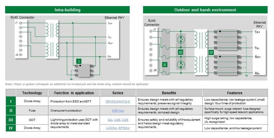
Figure 3. Recommended components for protecting PoE indoor and outdoor circuits
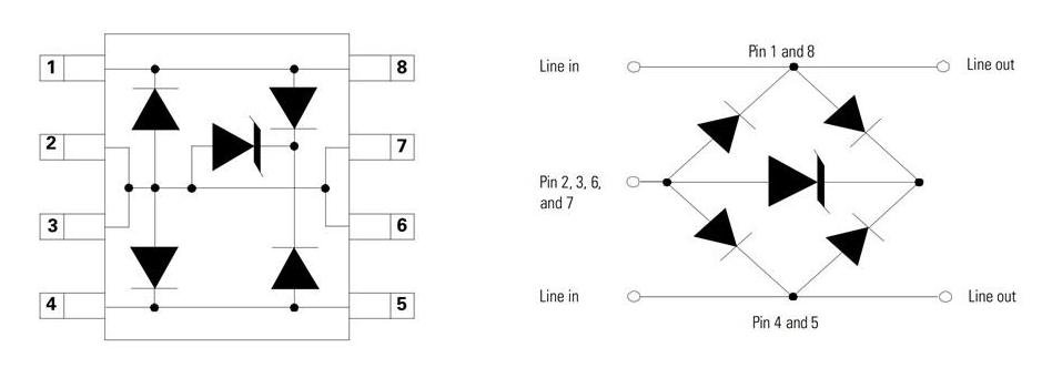
Figure 4 shows the schematic of the 2-channel TVS diode array. Consider using a protection diode array with the capability to absorb an ESD strike up to ±30 kV and a current surge in the range of 40 A.

Figure 4. Two-channel tvs diode array ic for voltage transient protection of an Ethernet phy circuit
To minimize signal distortion of the Tx and Rx signals, look for packages with no more than 2 pF capacitance to ground. Also, look for a TVS diode array with a low leakage current, such as less than 1 µA.
Protecting a PoE Network in an Outdoor Environment
The outdoors is a much more severe environment for electronics than indoors. There is a higher risk for power-cross to cause over-current faults and also a higher risk of lightning-induced surges events. Like the PoE++ protection circuit, a time-delay fuse is recommended on each I/O line for any outdoor and harsh environment PoE circuits to protect against power-cross events. An example is shown on the right side of Figure 3. For this challenging environment, in addition to fuses, gas discharge tubes should also be placed across the I/O lines. A gas discharge tube provides crowbar protection from lightning or other hazardous transients. A gas discharge tube has the following properties:
The capacity to absorb and survive a current surge up to 1000 A
Low capacitance, < 1 pF, independent of the voltage applied across the component
Versions that have surface-mount packaging.
Note that the fuse and gas discharge tube combination should meet all the regulatory requirements as described for the PoE++ standard.
As with the other circuits, a TVS diode array can protect the Ethernet PHY chipset. In the case of the outdoor environment PoE circuit, consider a higher power TVS diode array. One such higher power, TVS diode array is the 2-channel component shown in Figure 5.