

This article is the first in the "Protect Your Ports! Top Design Tips to Keep Your Communications Connected" series from Littelfuse.
Transmitting and receiving information between data ports on an information channel is the primary objective for the design of data communication systems. In addition, the communication systems need to be reliable so that they can be functional at all times ensuring critical data is not lost or interrupted. To develop robust and reliable communication systems, designers need to consider the impact of the external environment on their data ports. Disturbances such as lightning, electrostatic discharge (ESD), overcurrent surges, and overvoltage transients can damage the communication integrated circuits (ICs).
Designers have the challenges of incorporating protection against these disturbances into their designs without compromising the performance of their circuitry, maintaining the size requirements of the design, and controlling its cost. This article, the first in a series of three, will assist electronics design engineers in overcoming these challenges by offering protection schemes for their data port designs.
Part 1of this series will present protection recommendations for Power over Ethernet (PoE). The second and third parts will cover protecting high speed and low-speed interfaces.
PoE is a transmission technology that passes power along with data on Ethernet cabling. A single cable provides power and data to devices such as voice over internet protocol (VOIP) telephones, security cameras using internet protocol, wireless access points, data center network routers, and industrial control systems. The IEEE standard for PoE is 802.3 and has been evolving since 2003 to enable the use of higher power.
Table 1 shows the original and subsequent revisions of IEEE standard 802.3 to accommodate higher power transmissions.
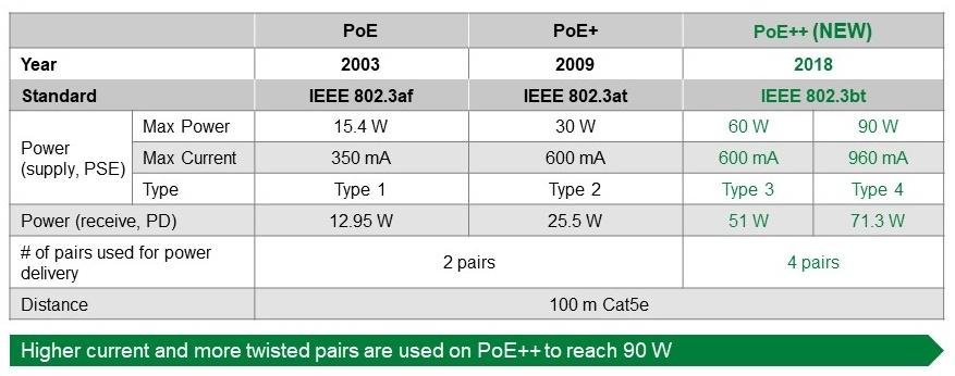
Table 1. Evolution of the ieee 802.3 standard to enable transmission at higher power
The 2018 evolution of the standard, 802.3bt, commonly referred to as PoE++, allows a maximum power of 90 W and as much as 960 mA of current on the data lines. Furthermore, this standard allows Ethernet transmission rates that can reach 10 Gbps, 10GBASE-T. However, the inclusion of power with low voltage digital signals requires that PoE circuits be protected from current overloads and voltage transients such as lightning, ESD, and other fast transients that propagate on an AC power line.
Protecting a PoE++ Port
Figure 1 illustrates an example PoE++ design and includes recommended protection components for current overload protection and transient voltage protection. The circuitry between the RJ45 connector and the protection network is designed to protect both the Ethernet Physical Layer (PHY) circuitry and the powered device (PD) controller.
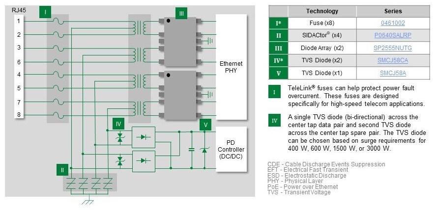
Figure 1. Recommended protection components for PoE++ protocol circuit
A fuse is recommended to protect each of the eight data lines from current overloads. Consider a slow blow fuse to avoid nuisance shutdowns from current surges due to a switching power supply or lightning surges. Another condition that the fuse can help avoid is damage due to an incorrectly wired or shorted power line. Ensure that the fuse you select is compliant with standards such as IEC 62368-1, Telcordia GR-1089, and FCC 47 Part 8 Surge Specifications. Fuses that meet these requirements have working current ratings of about 2A or less.
Look for a fuse with an interrupting rating of as much as 100 A so that the fuse can open and not vaporize even under the worst-case overload condition. Fuses that meet the referenced standards can open in approximately a second to a 250 % overload. To enable the efficient assembly of the PCB, select a surface mount version that is suitable for reflow soldering.
On the center tap of the isolating signal transformers, use a protection thyristor connected to earth ground to absorb and prevent voltage transients, including lightning strikes, from passing through the signal transformers. Protection thyristors, like Littelfuse SIDACtors®, are crowbar-type devices with low on-state voltage and the capacity to absorb high currents from transients.
Versions of protection thyristors can:
Crowbar a transient voltage to as low as 6 V
Absorb a surge current as high as 200 A
Minimize voltage overshoot
Have a low capacitance of around 100 pF
Absorb either polarity transient
Avoid degradation from multiple surge events.
A fuse combined with a protection thyristor complies with global regulatory standards, GR 1080 and IEC 62368-1, for protecting telecommunications equipment.
Protecting the Ethernet Physical Layer Chipset
For the Ethernet PHY chipset, the major transients that can cause damage are ESD strikes, cable discharge events, and electrical fast transients on the data lines. A transient voltage suppressor (TVS) diode array can provide the necessary protection. To protect all eight data lines, use two 4-channel TVS diode arrays as shown in Figure 2.
