

8.4.9Gateways
Gateways are used to control how the Process flows (how Tokens flow) through Sequence Flows as they converge and diverge within a Process. If the flow does not need to be controlled, then a Gateway is not needed. The term “gateway” implies that there is a gating mechanism that either allows or disallows passage through the Gateway; that is, as tokens arrive at a Gateway, they can be merged together on input and/or split apart on output as the Gateway mechanisms are invoked.
Gateways, like Activities, are capable of consuming or generating additional control tokens, effectively controlling the execution semantics of a given Process. The main difference is that Gateways do not represent ‘work’ being done and they are considered to have zero effect on the operational measures of the Process being executed (cost, time, etc.).
The Gateway controls the flow of both diverging and converging Sequence Flows. That is, a single Gateway could have multiple input and multiple output flows. Modelers and modeling tools might want to enforce a best practice of a Gateway only performing one of these functions. Thus, it would take two sequential Gateways to first converge and then to diverge the Sequence Flows.
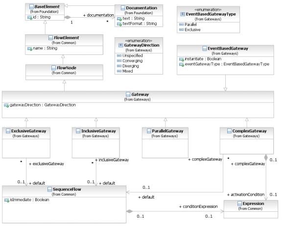
Figure 8.24 – Gateway class diagram
The details for the types of Gateways (Exclusive, Inclusive, Parallel, Event-Based, and Complex) is defined on page 285 for Processes and on page 342 for Choreographies.
88 |
Business Process Model and Notation (BPMN), v2.0.2 |
The Gateway class is an abstract type. Its concrete subclasses define the specific semantics of individual Gateway types, defining how the Gateway behaves in different situations.
The Gateway element inherits the attributes and model associations of FlowElement (see Table 8.44). Table 8.46 presents the additional attributes of the Gateway element.
Table 8.46 – Gateway attributes
Attribute Name |
Description/Usage |
||
|
|
||
gatewayDirection: GatewayDirection = |
An attribute that adds constraints on how the Gateway MAY be |
||
Unspecified |
used. |
||
{ Unspecified | Converging | Diverging | Mixed } |
|||
• |
Unspecified: There are no constraints. The Gateway MAY |
||
|
|||
|
|
have any number of incoming and outgoing Sequence |
|
|
|
Flows. |
|
|
• |
Converging: This Gateway MAY have multiple incoming |
|
|
|
Sequence Flows but MUST have no more than one (1) |
|
|
|
outgoing Sequence Flow. |
|
|
• |
Diverging: This Gateway MAY have multiple outgoing |
|
|
|
Sequence Flows but MUST have no more than one (1) |
|
|
|
incoming Sequence Flow. |
|
|
• |
Mixed: This Gateway contains multiple outgoing and |
|
|
|
multiple incoming Sequence Flows. |
|
|
|
|
|
8.4.10 Item Definition
BPMN elements, such as DataObjects and Messages, represent items that are manipulated, transferred, transformed, or stored during Process flows. These items can be either physical items, such as the mechanical part of a vehicle, or information items such the catalog of the mechanical parts of a vehicle.
An important characteristics of items in Process is their structure. BPMN does not require a particular format for this data structure, but it does designate XML Schema as its default. The structure attribute references the actual data structure.
The default format of the data structure for all elements can be specified in the Definitions element using the typeLanguage attribute. For example, a typeLanguage value of http://www.w3.org/2001/XMLSchema” indicates that the data structures using by elements within that Definitions are in the form of XML Schema types. If unspecified, the default is XML schema. An Import is used to further identify the location of the data structure (if applicable). For example, in the case of data structures contributed by an XML schema, an Import would be used to specify the file location of that schema.
Structure definitions are always defined as separate entities, so they cannot be inlined in one of their usages. You will see that in every mention of structure definition there is a “reference” to the element. This is why this class inherits from
RootElement.
An ItemDefinition element can specify an import reference where the proper definition of the structure is defined.
Business Process Model and Notation (BPMN), v2.0.2 |
89 |

In cases where the data structure represents a collection, the multiplicity can be projected into the attribute isCollection. If this attribute is set to “true,” but the actual type is not a collection type, the model is considered as invalid. BPMN compliant tools might support an automatic check for these inconsistencies and report this as an error. The default value for this element is “false.”
The itemKind attribute specifies the nature of an item which can be a physical or an information item.
Figure 8.25 shows the ItemDefinition class diagram. When an ItemDefinition is defined it is contained in
Definitions.
Figure 8.25 – ItemDefinition class diagram
The ItemDefinition element inherits the attributes and model associations BaseElement (see Table 8.5) through its relationship to RootElement. Table 8.47 presents the additional attributes and model associations for the
ItemDefinition element.
Table 8.47 – ItemDefinition attributes & model associations
Attribute Name |
Description/Usage |
|
|
itemKind: ItemKind = Information |
This defines the nature of the Item. Possible values are physical or |
{ Information | Physical } |
information. The default value is information. |
structureRef: [Element [0..1] |
The concrete data structure to be used. |
|
|
import: Import [0..1] |
Identifies the location of the data structure and its format. If the |
|
importType attribute is left unspecified, the typeLanguage specified |
|
in the Definitions that contains this ItemDefinition is assumed. |
isCollection: boolean = False |
Setting this flag to true indicates that the actual data type is a |
|
collection. |
|
|
90 |
Business Process Model and Notation (BPMN), v2.0.2 |
8.4.11 Message
A Message represents the content of a communication between two Participants. In BPMN 2.0.2, a Message is a graphical decorator (it was a supporting element in BPMN 1.2). An ItemDefinition is used to specify the Message structure.
When displayed in a diagram:
In a Message is a rectangle with converging diagonal lines in the upper half of the rectangle to give the appearance of an envelope (see Figure 8.26). It MUST be drawn with a single thin line.
The use of text, color, size, and lines for a Message MUST follow the rules defined in “Use of Text, Color, Size, and Lines in a Diagram” on page 39.
Figure 8.26 – A Message
In addition, when used in a Choreography Diagram more than one Message MAY be used for a single Choreography Task. In this case, it is important to know the first (initiating) Message of the interaction. For return (non-initiating) Messages the symbol of the Message is shaded with a light fill (see Figure 8.27).
Figure 8.27 – A non-initiating Message
Any Message sent by the non-initiating Participant or Sub-Choreography MUST be shaded with a light fill.
In a Collaboration, the communication itself is represented by a Message Flow (see “Message Flow” below for more details). The Message can be optionally depicted as a graphical decorator on a Message Flow in a Collaboration (see Figure 8.28 and Figure 8.29).
Business Process Model and Notation (BPMN), v2.0.2 |
91 |
Customer
Order 
 Confirmation
Supplier
Figure 8.28 – Messages Association overlapping Message Flows
In a Choreography, the communication is represented by a Choreography Task (see page 321). The Message can be depicted as a decorator with a Choreography Task in a Choreography (see Figure 8.29).
Order
Customer
Place
Order
Supplier
Confirmation
Figure 8.29 – Messages shown Associated with a Choreography Task
Figure 8.30 displays the class diagram showing the attributes and model associations for the Message element.
92 |
Business Process Model and Notation (BPMN), v2.0.2 |