

- •1 Scope
- •1.1 General
- •2 Conformance
- •2.1 General
- •2.2 Process Modeling Conformance
- •2.2.1 BPMN Process Types
- •2.2.2 BPMN Process Elements
- •Descriptive Conformance Sub-Class
- •Analytic Conformance Sub-Class
- •Common Executable Conformance Sub-Class
- •2.2.3 Visual Appearance
- •2.2.4 Structural Conformance
- •2.2.5 Process Semantics
- •2.2.6 Attributes and Model Associations
- •2.2.7 Extended and Optional Elements
- •2.2.8 Visual Interchange
- •2.3 Process Execution Conformance
- •2.3.1 Execution Semantics
- •2.3.2 Import of Process Diagrams
- •2.4 BPEL Process Execution Conformance
- •2.5 Choreography Modeling Conformance
- •2.5.1 BPMN Choreography Types
- •2.5.2 BPMN Choreography Elements
- •2.5.3 Visual Appearance
- •2.5.4 Choreography Semantics
- •2.5.5 Visual Interchange
- •2.6 Summary of BPMN Conformance Types
- •3 Normative References
- •3.1 General
- •3.2 Normative
- •3.3 Non-Normative
- •Activity Service
- •BPEL4People
- •Business Process Definition Metamodel
- •Business Process Modeling
- •Business Transaction Protocol
- •Dublin Core Meta Data
- •ebXML BPSS
- •Open Nested Transactions
- •SOAP 1.2
- •UDDI
- •WfMC Glossary
- •Web Services Transaction
- •Workflow Patterns
- •WSBPEL
- •WS-Coordination
- •WSDL
- •WS-HumanTask
- •XML 1.0 (Second Edition)
- •XML-Namespaces
- •XML-Schema
- •XPath
- •XPDL
- •4 Terms and Definitions
- •5 Symbols
- •6 Additional Information
- •6.1 Conventions
- •6.1.1 Typographical and Linguistic Conventions and Style
- •6.1.2 Abbreviations
- •6.2 Structure of this Document
- •6.3 Acknowledgments
- •Submitting Organizations
- •Supporting Organizations
- •Special Acknowledgments
- •7 Overview
- •7.1 General
- •7.2 BPMN Scope
- •7.2.1 Uses of BPMN
- •Private (Internal) Business Processes
- •Public Processes
- •Collaborations
- •Choreographies
- •Conversations
- •Diagram Point of View
- •Understanding the Behavior of Diagrams
- •7.3 BPMN Elements
- •7.3.1 Basic BPMN Modeling Elements
- •7.3.2 Extended BPMN Modeling Elements
- •7.4 BPMN Diagram Types
- •7.5 Use of Text, Color, Size, and Lines in a Diagram
- •7.6 Flow Object Connection Rules
- •7.6.1 Sequence Flow Connections Rules
- •7.6.2 Message Flow Connection Rules
- •7.7 BPMN Extensibility
- •7.8 BPMN Example
- •8 BPMN Core Structure
- •8.1 General
- •8.2 Infrastructure
- •8.2.1 Definitions
- •8.2.2 Import
- •8.2.3 Infrastructure Package XML Schemas
- •8.3 Foundation
- •8.3.1 Base Element
- •8.3.2 Documentation
- •8.3.3 Extensibility
- •Extension
- •ExtensionDefinition
- •ExtensionAttributeDefinition
- •ExtensionAttributeValue
- •Extensibility XML Schemas
- •XML Example
- •8.3.4 External Relationships
- •8.3.5 Root Element
- •8.3.6 Foundation Package XML Schemas
- •8.4 Common Elements
- •8.4.1 Artifacts
- •Common Artifact Definitions
- •Artifact Sequence Flow Connections
- •Artifact Message Flow Connections
- •Association
- •Group
- •Category
- •Text Annotation
- •XML Schema for Artifacts
- •8.4.2 Correlation
- •CorrelationKey
- •Key-based Correlation
- •Context-based Correlation
- •XML Schema for Correlation
- •8.4.3 Error
- •8.4.4 Escalation
- •8.4.5 Events
- •8.4.6 Expressions
- •Expression
- •Formal Expression
- •8.4.7 Flow Element
- •8.4.8 Flow Elements Container
- •8.4.9 Gateways
- •8.4.10 Item Definition
- •8.4.11 Message
- •8.4.12 Resources
- •8.4.13 Sequence Flow
- •Flow Node
- •8.4.14 Common Package XML Schemas
- •8.5 Services
- •8.5.1 Interface
- •8.5.2 EndPoint
- •8.5.3 Operation
- •8.5.4 Service Package XML Schemas
- •9 Collaboration
- •9.1 General
- •9.2 Basic Collaboration Concepts
- •9.2.1 Use of BPMN Common Elements
- •9.3 Pool and Participant
- •9.3.1 Participants
- •PartnerEntity
- •PartnerRole
- •Participant Multiplicity
- •ParticipantAssociation
- •9.3.2 Lanes
- •9.4 Message Flow
- •9.4.1 Interaction Node
- •9.4.2 Message Flow Associations
- •9.5 Conversations
- •9.5.1 Conversation Node
- •9.5.2 Conversation
- •9.5.3 Sub-Conversation
- •9.5.4 Call Conversation
- •9.5.5 Global Conversation
- •9.5.6 Conversation Link
- •9.5.7 Conversation Association
- •9.5.8 Correlations
- •9.6 Process within Collaboration
- •9.7 Choreography within Collaboration
- •9.8 Collaboration Package XML Schemas
- •10 Process
- •10.1 General
- •10.2 Basic Process Concepts
- •10.2.1 Types of BPMN Processes
- •10.2.2 Use of BPMN Common Elements
- •10.3 Activities
- •Sequence Flow Connections
- •Message Flow Connections
- •10.3.1 Resource Assignment
- •Resource Role
- •Expression Assignment
- •Parameterized Resource Assignment
- •10.3.2 Performer
- •10.3.3 Tasks
- •Service Task
- •Send Task
- •Receive Task
- •User Task
- •Manual Task
- •Business Rule
- •Script Task
- •10.3.4 Human Interactions
- •Notation
- •Manual Task
- •User Task
- •Rendering of User Tasks
- •Human Performers
- •Potential Owners
- •XML Schema for Human Interactions
- •Examples
- •10.3.5 Sub-Processes
- •Embedded Sub-Process (Sub-Process)
- •Reusable Sub-Process (Call Activity)
- •Event Sub-Process
- •Transaction
- •Ad-Hoc Sub-Process
- •10.3.6 Call Activity
- •Callable Element
- •10.3.7 Global Task
- •Types of Global Task
- •10.3.8 Loop Characteristics
- •Standard Loop Characteristics
- •Multi-Instance Characteristics
- •Complex Behavior Definition
- •10.3.9 XML Schema for Activities
- •10.4 Items and Data
- •10.4.1 Data Modeling
- •Item-Aware Elements
- •Data Objects
- •DataObject
- •States
- •Data Objects representing a Collection of Data
- •Visual representations of Data Objects
- •Lifecycle and Accessibility
- •Data Stores
- •Properties
- •Lifecycle and Accessibility
- •Data Inputs and Outputs
- •Data Input
- •States
- •Data Output
- •States
- •Service Task Mapping
- •Send Task Mapping
- •Receive Task Mapping
- •User Task Mapping
- •Call Activity Mapping
- •Script Task Mapping
- •Events
- •InputSet
- •OutputSet
- •Data Associations
- •DataAssociation
- •Assignment
- •DataInputAssociation
- •DataOutputAssociation
- •Data Objects associated with a Sequence Flow
- •10.4.2 Execution Semantics for Data
- •Execution Semantics for DataAssociation
- •10.4.3 Usage of Data in XPath Expressions
- •Access to BPMN Data Objects
- •Access to BPMN Data Input and Data Output
- •Access to BPMN Properties
- •For BPMN Instance Attributes
- •10.4.4 XML Schema for Data
- •10.5 Events
- •10.5.1 Concepts
- •Data Modeling and Events
- •Common Event attributes
- •Common Catch Event attributes
- •Common Throw Event Attributes
- •Implicit Throw Event
- •10.5.2 Start Event
- •Start Event Triggers
- •Start Events for Top-level Processes
- •Start Events for Sub-Processes
- •Start Events for Event Sub-Processes
- •Attributes for Start Events
- •Sequence Flow Connections
- •Message Flow Connections
- •10.5.3 End Event
- •End Event Results
- •Sequence Flow Connections
- •Message Flow Connections
- •10.5.4 Intermediate Event
- •Intermediate Event Triggers
- •Intermediate Events in Normal Flow
- •Intermediate Events Attached to an Activity Boundary
- •Attributes for Boundary Events
- •Activity Boundary Connections
- •Sequence Flow Connections
- •Message Flow Connections
- •10.5.5 Event Definitions
- •Event Definition Metamodel
- •Cancel Event
- •Compensation Event
- •Conditional Event
- •Error Event
- •Escalation Event Definition
- •Link Event Definition
- •Message Event Definition
- •Multiple Event
- •None Event
- •Parallel Multiple Event
- •Signal Event
- •Terminate Event
- •Timer Event
- •10.5.6 Handling Events
- •Handling Start Events
- •Handling Events within normal Sequence Flow (Intermediate Events)
- •Handling Events attached to an Activity (Intermediate boundary Events and Event Sub-Processes)
- •Interrupting Event Handlers (Error, Escalation, Message, Signal, Timer, Conditional, Multiple, and Parallel Multiple)
- •Non-interrupting Event Handlers (Escalation, Message, Signal, Timer, Conditional, Multiple, and Parallel Multiple)
- •Handling End Events
- •10.5.7 Scopes
- •10.5.8 Events Package XML Schemas
- •10.6 Gateways
- •10.6.1 Sequence Flow Considerations
- •10.6.2 Exclusive Gateway
- •10.6.3 Inclusive Gateway
- •10.6.4 Parallel Gateway
- •10.6.5 Complex Gateway
- •10.6.6 Event-Based Gateway
- •10.6.7 Gateway Package XML Schemas
- •10.7 Compensation
- •10.7.1 Compensation Handler
- •10.7.2 Compensation Triggering
- •10.7.3 Relationship between Error Handling and Compensation
- •10.8 Lanes
- •10.9 Process Instances, Unmodeled Activities, and Public Processes
- •10.10 Auditing
- •10.11 Monitoring
- •10.12 Process Package XML Schemas
- •11 Choreography
- •11.1 General
- •11.2 Basic Choreography Concepts
- •11.3 Data
- •11.4 Use of BPMN Common Elements
- •11.4.1 Sequence Flow
- •11.4.2 Artifacts
- •11.5 Choreography Activities
- •11.5.1 Choreography Task
- •11.5.2 Sub-Choreography
- •The Parent Sub-Choreography (Expanded)
- •11.5.3 Call Choreography
- •11.5.4 Global Choreography Task
- •11.5.5 Looping Activities
- •11.5.6 The Sequencing of Activities
- •11.6 Events
- •11.6.1 Start Events
- •11.6.2 Intermediate Events
- •11.6.3 End Events
- •11.7 Gateways
- •11.7.1 Exclusive Gateway
- •11.7.2 Event-Based Gateway
- •11.7.3 Inclusive Gateway
- •11.7.4 Parallel Gateway
- •11.7.5 Complex Gateway
- •11.7.6 Chaining Gateways
- •11.8 Choreography within Collaboration
- •11.8.1 Participants
- •11.8.2 Swimlanes
- •Choreography Task in Combined View
- •Sub-Choreography in Combined View
- •11.9 XML Schema for Choreography
- •12 BPMN Notation and Diagrams
- •12.1 BPMN Diagram Interchange (BPMN DI)
- •12.1.1 Scope
- •12.1.2 Diagram Definition and Interchange
- •12.1.3 How to Read this Clause
- •12.2 BPMN Diagram Interchange (DI) Meta-model
- •12.2.1 Overview
- •12.2.2 Abstract Syntax
- •12.2.3 Classifier Descriptions
- •12.2.4 Complete BPMN DI XML Schema
- •12.3 Notational Depiction Library and Abstract Element Resolutions
- •12.3.1 Labels
- •12.3.2 BPMNShape
- •Markers for Activities
- •Tasks [BPMNShape]
- •Collapsed Sub-Processes [BPMNShape]
- •Expanded Sub-Processes [BPMNShape]
- •Collapsed Ad Hoc Sub-Processes [BPMNShape]
- •Expanded Ad Hoc Sub-Processes [BPMNShape]
- •Collapsed Transactions [BPMNShape]
- •Expanded Transactions [BPMNShape]
- •Collapsed Event Sub-Processes [BPMNShape]
- •Expanded Event Sub-Processes [BPMNShape]
- •Call Activities (Calling a Global Task) [BPMNShape]
- •Collapsed Call Activities (Calling a Process) [BPMNShape]
- •Expanded Call Activities (Calling a Process) [BPMNShape]
- •Data [BPMNShape]
- •Events [BPMNShape]
- •Gateways [BPMNShape]
- •Artifacts [BPMNShape]
- •Lanes [BPMNShape]
- •Pools [BPMNShape]
- •Choreography Tasks [BPMNShape]
- •Collapsed Sub-Choreographies [BPMNShape]
- •Expanded Sub-Choreographies [BPMNShape]
- •Call Choreographies (Calling a Global Choreography Task) [BPMNShape]
- •Collapsed Call Choreographies (Calling a Choreography) [BPMNShape]
- •Expanded Call Choreographies (Calling a Choreography) [BPMNShape]
- •Choreography Participant Bands [BPMNShape]
- •Conversations [BPMNShape]
- •12.3.3 BPMNEdge
- •Connecting Objects [BPMNEdge]
- •12.4 Example(s)
- •12.4.1 Depicting Content in a Sub-Process
- •Expanded Sub-Process
- •Expanded Sub-Process with Start and End Events on Border
- •Collapsed Sub-Process
- •12.4.2 Multiple Lanes and Nested Lanes
- •12.4.3 Vertical Collaboration
- •12.4.4 Conversation
- •12.4.5 Choreography
- •13 BPMN Execution Semantics
- •13.1 General
- •13.2 Process Instantiation and Termination
- •13.3 Activities
- •13.3.1 Sequence Flow Considerations
- •13.3.2 Activity
- •13.3.3 Task
- •13.3.4 Sub-Process/Call Activity
- •13.3.5 Ad-Hoc Sub-Process
- •Operational semantics
- •13.3.6 Loop Activity
- •13.3.7 Multiple Instances Activity
- •13.4 Gateways
- •13.4.1 Parallel Gateway (Fork and Join)
- •13.4.2 Exclusive Gateway (Exclusive Decision (data-based) and Exclusive Merge)
- •13.4.3 Inclusive Gateway (Inclusive Decision and Inclusive Merge)
- •13.4.4 Event-based Gateway (Exclusive Decision (event-based))
- •13.4.5 Complex Gateway (related to Complex Condition and Complex Merge)
- •13.5 Events
- •13.5.1 Start Events
- •13.5.2 Intermediate Events
- •13.5.3 Intermediate Boundary Events
- •13.5.4 Event Sub-Processes
- •Operational semantics
- •13.5.5 Compensation
- •Compensation Handler
- •Compensation Triggering
- •Relationship between Error Handling and Compensation
- •Operational Semantics
- •13.5.6 End Events
- •Process level end events
- •Sub-process level end events
- •14 Mapping BPMN Models to WS-BPEL
- •14.1 General
- •14.2 Basic BPMN-BPEL Mapping
- •14.2.1 Process
- •14.2.2 Activities
- •Common Activity Mappings
- •Task Mappings
- •Service Task
- •Receive Task
- •Send Task
- •Abstract Task
- •Service Package
- •Message
- •Interface and Operation
- •Conversations and Correlation
- •Sub-Process Mappings
- •Mapping of Event Sub-Processes
- •Activity Loop Mapping
- •Standard Loops
- •Dealing with LoopMaximum
- •Multi-Instance Activities
- •14.2.3 Events
- •Start Event Mappings
- •Message Start Events
- •Error Start Events
- •Compensation Start Events
- •Intermediate Event Mappings (Non-boundary)
- •Message Intermediate Events (Non-boundary)
- •Timer Intermediate Events (Non-boundary)
- •Compensation Intermediate Events (Non-boundary)
- •End Event Mappings
- •None End Events
- •Message End Events
- •Error End Events
- •Compensation End Events
- •Terminate End Events
- •Boundary Intermediate Events
- •Message Boundary Events
- •Error Boundary Events
- •Compensation Boundary Events
- •Multiple Boundary Events, and Boundary Events with Loops
- •14.2.4 Gateways and Sequence Flows
- •Exclusive (Data-based) Decision Pattern
- •Exclusive (Event-based) Decision Pattern
- •Inclusive Decision Pattern
- •Parallel Pattern
- •Sequence Pattern
- •Structured Loop Patterns
- •Handling Loops in Sequence Flows
- •14.2.5 Handling Data
- •Data Objects
- •Properties
- •Input and Output Sets
- •Data Associations
- •Expressions
- •Assignments
- •14.3 Extended BPMN-BPEL Mapping
- •14.3.1 End Events
- •14.3.2 Loop/Switch Combinations From a Gateway
- •14.3.3 Interleaved Loops
- •14.3.4 Infinite Loops
- •14.3.5 BPMN Elements that Span Multiple WSBPEL Sub-Elements
- •15 Exchange Formats
- •15.1 Interchanging Incomplete Models
- •15.2 Machine Readable Files
- •15.3.1 Document Structure
- •15.3.2 References within the BPMN XSD
- •15.5 XSLT Transformation between XSD and XMI
- •B.1 Scope
- •B.2 Architecture
- •B.3 Diagram Common
- •B.3.1 Overview
- •B.3.2 Abstract Syntax
- •B.3.3 Classifier Descriptions
- •B.4 Diagram Interchange
- •B.4.1 Overview
- •B.4.2 Abstract Syntax
- •B.4.3 Classifier Descriptions
If the Participant is the receiver of only one such Message, that is also consumed through a receive following the Event-Based Gateway. This is because the Participant Process does not know whether it will receive a Message (since the Gateway entails a choice of outcomes).
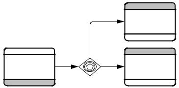
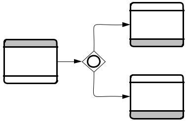
11.7.2 Event-Based Gateway
As described above, the Event-Based Gateway represents a branching point in the Process where the alternatives are based on Events that occur at that point in the Process, rather than the evaluation of expressions using Process data. For details of how Event-Based Gateways are used within an Orchestration Process see “Event-Based Gateway” on page 296.
These Gateways are used in Choreography when the data used to make the decision is only visible to the internal Processes of one Participant. That is, there has been no Message sent within the Choreography that would expose the data used to make the decision. Thus, the only way that the other Participants can be aware of the results of the decision is by the particular Message that arrives next.
On the right side of the Gateway: either the senders MUST to be the same; or the receivers MUST to be the same.
After the first Choreography Activity occurs, the other Choreography Activities for the
Gateway MUST NOT occur.
Message Intermediate Events MUST NOT be used in the Event-Based Gateway.
Timer Intermediate Events MAY be used, but they restrict the participation in the Gateway.
For relative timers: All Participants on the right side of the Gateway MUST be involved in the
Choreography Activity that immediately precedes the Gateway.
For absolute timers (full time/date): All Participants on the right side of the Gateway MUST be involved in the Choreography Activity that immediately precedes the Gateway.
Signal Intermediate Events MAY be used (they are visible to all Participants). No other types of Intermediate Events are allowed.
|
P articipant A |
|
C horeography |
|
T ask 2 |
|
P articipant B |
P articipant A |
P articipant A |
|
D e cicio n ? |
C horeography |
C horeography |
T ask 1 |
T ask 3 |
P articipant B |
P articipant B |
Figure 11.38 – An example of an Event Gateway
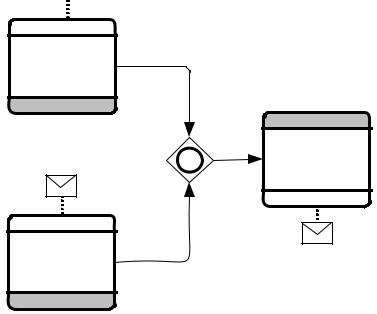
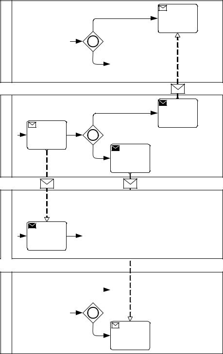
Figure 11.39 displays the corresponding Collaboration view of the above Choreography Event Gateway configuration.
Business Process Model and Notation (BPMN), v2.0.2 |
349 |

|
|
Yes |
Receive |
A |
|
|
Message |
|
|
|
|
Participant |
Send |
|
|
Message |
|
|
|
|
Receive |
|
|
|
|
|
|
|
No |
Message |
|
|
M1 |
M2 |
M3 |
|
Yes |
Send |
|
|
|
Message |
|
B |
Decision? |
|
|
Participant |
|
|
|
Receive |
|
|
|
Message |
|
|
|
|
|
|
|
|
|
|
Send |
|
|
No |
Message |
Figure 11.39 – The corresponding Collaboration view of the above Choreography Event Gateway configuration
The REQUIRED execution behavior of the Event-Based Gateway and associated Choreography Activities are enforced through the Business Processes of the Participants as follows:
•Each Choreography Activity and the Sequence Flow connections is reflected in each Participant Process.
•If the senders following the Gateway are the same, the Event-Based Gateway is reflected as an Exclusive Gateway in that Participant’s Process. This is because the choice of which Message to send is determined by the same Participant. If the senders are different, sending occurs through different Processes.
•If the receivers are the same, the senders can be the same or different. In this case, the Event-Based Gateway is reflected in the receiver’s Process, with the different Message receives following the Gateway.
•If the receivers are different, the senders need to be the same. The Event-Based Gateway is reflected for different receiver Processes such that the respective receive follows the Gateway. A time-out can be used to ensure that the Gateway does not wait indefinitely.
350 |
Business Process Model and Notation (BPMN), v2.0.2 |
11.7.3 Inclusive Gateway
Inclusive Gateways are used for modeling points of synchronization of a number of branches, not all of which are active, after which one or more alternative branches are chosen within a Choreography flow. For example, one of more branches MAY be activated upstream, in parallel, depending on the nature of goods in an order (e.g., large orders, fragile goods orders, orders belonging to pre-existing shipment contracts), and these are subsequently merged. The point of merge results in one or more risk mitigating outcomes (e.g., special insurance protection needed, special packaging needed, and different container categories needed). Inclusive Gateways are also used within an Orchestration Process see page 291.
Like Exclusive Gateways, Inclusive Gateways are used in a Choreography, but they are constrained by the lack of a central mechanism to store the data that will be used in the Condition expressions of the Gateway’s outgoing Sequence Flows. Choreographies MAY contain natural language descriptions of the Gateway’s Conditions to document the one more alternative paths of the Choreography (e.g., “special insurance protection needed,” “special packaging needed,” and different “container category needed”), but such Choreographies would be underspecified and would not be enforceable. To create an enforceable Choreography, the Gateway Conditions MUST be formal Condition Expressions. In general the following rules apply for the Expressions.
Like the enforceability of the Exclusive Gateway, the Inclusive Gateway in a Choreography requires that the data in the Expressions of the outgoing Sequence Flows of the Gateway be available to the initiators of the
Choreography Activities of outgoing Sequence Flows. This means that the initiators of these Choreography Activities should also be senders or receivers of Messages in Choreography Activities immediately preceding the Gateway. The major difference, however, is that the synchronizing behavior of the Inclusive Gateway can only be enforced through one participant. Hence, the rules for enforceability are as follows:
The data used for Gateway Conditions MUST have been in a Message that was sent prior to (upstream from) the
Gateway.
More specifically, all Participants that are directly affected by the Gateway MUST have either sent or received the Message(s) that contained the data used in the Conditions.
Furthermore, all these Participants MUST have the same understanding of the data. That is, the actual values of the data cannot selectively change after a Participant has seen a Message. Changes to data during the course of the Choreography MUST be visible to all the Participants affected by the
Gateway.
Merge: In order to enforce the synchronizing merge of the Gateway, the sender of the Choreography Activity after the Gateway MUST participate in the Gateway immediately preceding the Gateway. This ensures that the merge can be enforced. (This relies on the assumption of logical atomicity of a Choreography Activity, otherwise the rule would require that all receivers are the same so that the Gateway is enforced in the receiver’s Process only).
Split: In order to enforce the split side of the Gateway, the initiators of all Choreography Activities immediately following the Gateway MUST be the same as the common sender or receiver of Choreography Activities preceding the Gateway. The sender(s) of all the Choreography Activities after the Gateway
MUST be involved in all the Choreography Activities that immediately precede the Gateway.
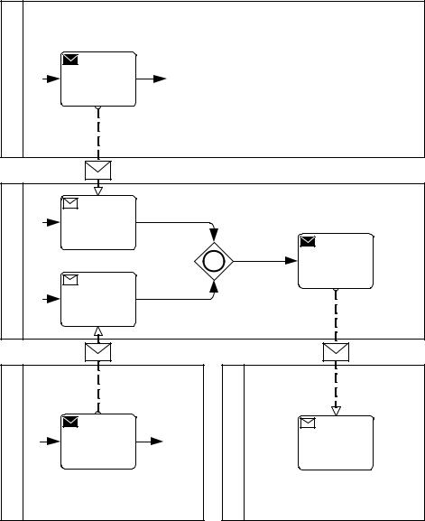
Figure 11.40 shows an example of a Choreography with an Inclusive Gateway. The Gateway is enforced in the corresponding Business Processes of the Participants involved. For the merge behavior to be enforced, the initiator of Choreography Activities immediately following the Gateway participates in the Choreography Activities immediately preceding the Gateway.
Business Process Model and Notation (BPMN), v2.0.2 |
351 |
 M1
M1
Participant A
Choreography
Task 1
Participant B
Participant D
Choreography
Task 1
M2
Participant B
Participant C |
M3 |
Choreography |
|
Task 1 |
|
Participant B |
|
Figure 11.40 – An example of a Choreography Inclusive Gateway configuration
352 |
Business Process Model and Notation (BPMN), v2.0.2 |
Participant A
Send
Message
|
M1 |
|
|
Receive |
|
B |
Message |
|
Participant |
|
Send |
|
Message |
|
Receive |
|
|
|
|
|
|
Message |
|
|
M2 |
M3 |
Participant C
Send
Message
Participant D
Receive
Message
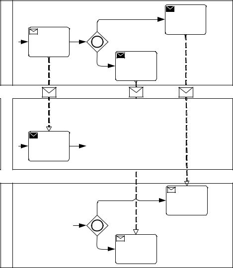
Figure 11.41 – The corresponding Collaboration view of the above Choreography Inclusive Gateway configuration
Figure 11.42, a variation of Figure 11.40 above, shows an example of a Choreography illustrating the enforcement of the split behavior of the Inclusive Gateway. For the split behavior to be enforced, the initiators of Choreography Activities immediately following the Gateway and the receiver of Choreography Activities immediately preceding the Gateway are the same Participant (i.e., A).
Business Process Model and Notation (BPMN), v2.0.2 |
353 |

|
Participant A |
Condition 1 |
Choreography |
|
Task 2 |
Participant A |
Participant C |
Decision? |
|
Choreography |
|
Task 1 |
|
Participant B |
Participant A |
|
Choreography |
Condition 2 |
Task 3 |
|
Participant C |
Figure 11.42 – An example of a Choreography Inclusive Gateway configuration
354 |
Business Process Model and Notation (BPMN), v2.0.2 |
|
|
Condition 1 |
Send |
|
A |
|
|
|
Message |
|
Decision? |
|
|
|
Participant |
Receive |
|
|
|
|
|
|
||
Message |
|
|
|
|
|
|
Send |
|
|
|
|
|
|
|
|
|
Condition 2 |
Message |
|
|
|
|
|
|
|
M1 |
|
M2 |
M3 |
B |
|
|
|
|
Participant |
Send |
|
|
|
Message |
|
|
|
|
|
|
Condition 1 |
Receive |
|
C |
|
|
|
Message |
|
Decision? |
|
|
|
Participant |
|
|
|
|
|
|
Receive |
|
|
|
|
|
|
|
|
|
Condition 2 |
Message |
|
|
|
|
|
|
Figure 11.43 – The corresponding Collaboration view of the above Choreography
Inclusive Gateway configuration
Business Process Model and Notation (BPMN), v2.0.2 |
355 |
|
Participant A |
Condition 1 |
Choreography |
|
Task 2 |
Participant A |
Participant C |
Decision? |
|
Choreography |
|
Task 1 |
|
Participant B |
Participant A |
|
Choreography |
Condition 2 |
Task 3 |
|
Participant D |
Figure 11.44 – Another example of a Choreography Inclusive Gateway configuration
356 |
Business Process Model and Notation (BPMN), v2.0.2 |
Participant D
Condition 1 |
|
Receive |
|
||
|
Message |
|
Decision?
Condition 2
|
|
|
|
M3 |
|
|
Condition 1 |
Send |
|
A |
|
|
|
Message |
|
Decision? |
|
|
|
Participant |
Receive |
|
|
|
|
|
|
||
Message |
|
|
|
|
|
|
Send |
|
|
|
|
|
|
|
|
|
Condition 2 |
Message |
|
|
|
|
|
|
|
M1 |
|
M2 |
|
B |
|
|
|
|
Participant |
Send |
|
|
|
Message |
|
|
|
|
Participant C
Condition 1
Decision?
|
Receive |
Condition 2 |
Message |
|
Figure 11.45 – The corresponding Collaboration view of the above Choreography Inclusive Gateway configuration
Business Process Model and Notation (BPMN), v2.0.2 |
357 |