
- •1 Scope
- •1.1 General
- •2 Conformance
- •2.1 General
- •2.2 Process Modeling Conformance
- •2.2.1 BPMN Process Types
- •2.2.2 BPMN Process Elements
- •Descriptive Conformance Sub-Class
- •Analytic Conformance Sub-Class
- •Common Executable Conformance Sub-Class
- •2.2.3 Visual Appearance
- •2.2.4 Structural Conformance
- •2.2.5 Process Semantics
- •2.2.6 Attributes and Model Associations
- •2.2.7 Extended and Optional Elements
- •2.2.8 Visual Interchange
- •2.3 Process Execution Conformance
- •2.3.1 Execution Semantics
- •2.3.2 Import of Process Diagrams
- •2.4 BPEL Process Execution Conformance
- •2.5 Choreography Modeling Conformance
- •2.5.1 BPMN Choreography Types
- •2.5.2 BPMN Choreography Elements
- •2.5.3 Visual Appearance
- •2.5.4 Choreography Semantics
- •2.5.5 Visual Interchange
- •2.6 Summary of BPMN Conformance Types
- •3 Normative References
- •3.1 General
- •3.2 Normative
- •3.3 Non-Normative
- •Activity Service
- •BPEL4People
- •Business Process Definition Metamodel
- •Business Process Modeling
- •Business Transaction Protocol
- •Dublin Core Meta Data
- •ebXML BPSS
- •Open Nested Transactions
- •SOAP 1.2
- •UDDI
- •WfMC Glossary
- •Web Services Transaction
- •Workflow Patterns
- •WSBPEL
- •WS-Coordination
- •WSDL
- •WS-HumanTask
- •XML 1.0 (Second Edition)
- •XML-Namespaces
- •XML-Schema
- •XPath
- •XPDL
- •4 Terms and Definitions
- •5 Symbols
- •6 Additional Information
- •6.1 Conventions
- •6.1.1 Typographical and Linguistic Conventions and Style
- •6.1.2 Abbreviations
- •6.2 Structure of this Document
- •6.3 Acknowledgments
- •Submitting Organizations
- •Supporting Organizations
- •Special Acknowledgments
- •7 Overview
- •7.1 General
- •7.2 BPMN Scope
- •7.2.1 Uses of BPMN
- •Private (Internal) Business Processes
- •Public Processes
- •Collaborations
- •Choreographies
- •Conversations
- •Diagram Point of View
- •Understanding the Behavior of Diagrams
- •7.3 BPMN Elements
- •7.3.1 Basic BPMN Modeling Elements
- •7.3.2 Extended BPMN Modeling Elements
- •7.4 BPMN Diagram Types
- •7.5 Use of Text, Color, Size, and Lines in a Diagram
- •7.6 Flow Object Connection Rules
- •7.6.1 Sequence Flow Connections Rules
- •7.6.2 Message Flow Connection Rules
- •7.7 BPMN Extensibility
- •7.8 BPMN Example
- •8 BPMN Core Structure
- •8.1 General
- •8.2 Infrastructure
- •8.2.1 Definitions
- •8.2.2 Import
- •8.2.3 Infrastructure Package XML Schemas
- •8.3 Foundation
- •8.3.1 Base Element
- •8.3.2 Documentation
- •8.3.3 Extensibility
- •Extension
- •ExtensionDefinition
- •ExtensionAttributeDefinition
- •ExtensionAttributeValue
- •Extensibility XML Schemas
- •XML Example
- •8.3.4 External Relationships
- •8.3.5 Root Element
- •8.3.6 Foundation Package XML Schemas
- •8.4 Common Elements
- •8.4.1 Artifacts
- •Common Artifact Definitions
- •Artifact Sequence Flow Connections
- •Artifact Message Flow Connections
- •Association
- •Group
- •Category
- •Text Annotation
- •XML Schema for Artifacts
- •8.4.2 Correlation
- •CorrelationKey
- •Key-based Correlation
- •Context-based Correlation
- •XML Schema for Correlation
- •8.4.3 Error
- •8.4.4 Escalation
- •8.4.5 Events
- •8.4.6 Expressions
- •Expression
- •Formal Expression
- •8.4.7 Flow Element
- •8.4.8 Flow Elements Container
- •8.4.9 Gateways
- •8.4.10 Item Definition
- •8.4.11 Message
- •8.4.12 Resources
- •8.4.13 Sequence Flow
- •Flow Node
- •8.4.14 Common Package XML Schemas
- •8.5 Services
- •8.5.1 Interface
- •8.5.2 EndPoint
- •8.5.3 Operation
- •8.5.4 Service Package XML Schemas
- •9 Collaboration
- •9.1 General
- •9.2 Basic Collaboration Concepts
- •9.2.1 Use of BPMN Common Elements
- •9.3 Pool and Participant
- •9.3.1 Participants
- •PartnerEntity
- •PartnerRole
- •Participant Multiplicity
- •ParticipantAssociation
- •9.3.2 Lanes
- •9.4 Message Flow
- •9.4.1 Interaction Node
- •9.4.2 Message Flow Associations
- •9.5 Conversations
- •9.5.1 Conversation Node
- •9.5.2 Conversation
- •9.5.3 Sub-Conversation
- •9.5.4 Call Conversation
- •9.5.5 Global Conversation
- •9.5.6 Conversation Link
- •9.5.7 Conversation Association
- •9.5.8 Correlations
- •9.6 Process within Collaboration
- •9.7 Choreography within Collaboration
- •9.8 Collaboration Package XML Schemas
- •10 Process
- •10.1 General
- •10.2 Basic Process Concepts
- •10.2.1 Types of BPMN Processes
- •10.2.2 Use of BPMN Common Elements
- •10.3 Activities
- •Sequence Flow Connections
- •Message Flow Connections
- •10.3.1 Resource Assignment
- •Resource Role
- •Expression Assignment
- •Parameterized Resource Assignment
- •10.3.2 Performer
- •10.3.3 Tasks
- •Service Task
- •Send Task
- •Receive Task
- •User Task
- •Manual Task
- •Business Rule
- •Script Task
- •10.3.4 Human Interactions
- •Notation
- •Manual Task
- •User Task
- •Rendering of User Tasks
- •Human Performers
- •Potential Owners
- •XML Schema for Human Interactions
- •Examples
- •10.3.5 Sub-Processes
- •Embedded Sub-Process (Sub-Process)
- •Reusable Sub-Process (Call Activity)
- •Event Sub-Process
- •Transaction
- •Ad-Hoc Sub-Process
- •10.3.6 Call Activity
- •Callable Element
- •10.3.7 Global Task
- •Types of Global Task
- •10.3.8 Loop Characteristics
- •Standard Loop Characteristics
- •Multi-Instance Characteristics
- •Complex Behavior Definition
- •10.3.9 XML Schema for Activities
- •10.4 Items and Data
- •10.4.1 Data Modeling
- •Item-Aware Elements
- •Data Objects
- •DataObject
- •States
- •Data Objects representing a Collection of Data
- •Visual representations of Data Objects
- •Lifecycle and Accessibility
- •Data Stores
- •Properties
- •Lifecycle and Accessibility
- •Data Inputs and Outputs
- •Data Input
- •States
- •Data Output
- •States
- •Service Task Mapping
- •Send Task Mapping
- •Receive Task Mapping
- •User Task Mapping
- •Call Activity Mapping
- •Script Task Mapping
- •Events
- •InputSet
- •OutputSet
- •Data Associations
- •DataAssociation
- •Assignment
- •DataInputAssociation
- •DataOutputAssociation
- •Data Objects associated with a Sequence Flow
- •10.4.2 Execution Semantics for Data
- •Execution Semantics for DataAssociation
- •10.4.3 Usage of Data in XPath Expressions
- •Access to BPMN Data Objects
- •Access to BPMN Data Input and Data Output
- •Access to BPMN Properties
- •For BPMN Instance Attributes
- •10.4.4 XML Schema for Data
- •10.5 Events
- •10.5.1 Concepts
- •Data Modeling and Events
- •Common Event attributes
- •Common Catch Event attributes
- •Common Throw Event Attributes
- •Implicit Throw Event
- •10.5.2 Start Event
- •Start Event Triggers
- •Start Events for Top-level Processes
- •Start Events for Sub-Processes
- •Start Events for Event Sub-Processes
- •Attributes for Start Events
- •Sequence Flow Connections
- •Message Flow Connections
- •10.5.3 End Event
- •End Event Results
- •Sequence Flow Connections
- •Message Flow Connections
- •10.5.4 Intermediate Event
- •Intermediate Event Triggers
- •Intermediate Events in Normal Flow
- •Intermediate Events Attached to an Activity Boundary
- •Attributes for Boundary Events
- •Activity Boundary Connections
- •Sequence Flow Connections
- •Message Flow Connections
- •10.5.5 Event Definitions
- •Event Definition Metamodel
- •Cancel Event
- •Compensation Event
- •Conditional Event
- •Error Event
- •Escalation Event Definition
- •Link Event Definition
- •Message Event Definition
- •Multiple Event
- •None Event
- •Parallel Multiple Event
- •Signal Event
- •Terminate Event
- •Timer Event
- •10.5.6 Handling Events
- •Handling Start Events
- •Handling Events within normal Sequence Flow (Intermediate Events)
- •Handling Events attached to an Activity (Intermediate boundary Events and Event Sub-Processes)
- •Interrupting Event Handlers (Error, Escalation, Message, Signal, Timer, Conditional, Multiple, and Parallel Multiple)
- •Non-interrupting Event Handlers (Escalation, Message, Signal, Timer, Conditional, Multiple, and Parallel Multiple)
- •Handling End Events
- •10.5.7 Scopes
- •10.5.8 Events Package XML Schemas
- •10.6 Gateways
- •10.6.1 Sequence Flow Considerations
- •10.6.2 Exclusive Gateway
- •10.6.3 Inclusive Gateway
- •10.6.4 Parallel Gateway
- •10.6.5 Complex Gateway
- •10.6.6 Event-Based Gateway
- •10.6.7 Gateway Package XML Schemas
- •10.7 Compensation
- •10.7.1 Compensation Handler
- •10.7.2 Compensation Triggering
- •10.7.3 Relationship between Error Handling and Compensation
- •10.8 Lanes
- •10.9 Process Instances, Unmodeled Activities, and Public Processes
- •10.10 Auditing
- •10.11 Monitoring
- •10.12 Process Package XML Schemas
- •11 Choreography
- •11.1 General
- •11.2 Basic Choreography Concepts
- •11.3 Data
- •11.4 Use of BPMN Common Elements
- •11.4.1 Sequence Flow
- •11.4.2 Artifacts
- •11.5 Choreography Activities
- •11.5.1 Choreography Task
- •11.5.2 Sub-Choreography
- •The Parent Sub-Choreography (Expanded)
- •11.5.3 Call Choreography
- •11.5.4 Global Choreography Task
- •11.5.5 Looping Activities
- •11.5.6 The Sequencing of Activities
- •11.6 Events
- •11.6.1 Start Events
- •11.6.2 Intermediate Events
- •11.6.3 End Events
- •11.7 Gateways
- •11.7.1 Exclusive Gateway
- •11.7.2 Event-Based Gateway
- •11.7.3 Inclusive Gateway
- •11.7.4 Parallel Gateway
- •11.7.5 Complex Gateway
- •11.7.6 Chaining Gateways
- •11.8 Choreography within Collaboration
- •11.8.1 Participants
- •11.8.2 Swimlanes
- •Choreography Task in Combined View
- •Sub-Choreography in Combined View
- •11.9 XML Schema for Choreography
- •12 BPMN Notation and Diagrams
- •12.1 BPMN Diagram Interchange (BPMN DI)
- •12.1.1 Scope
- •12.1.2 Diagram Definition and Interchange
- •12.1.3 How to Read this Clause
- •12.2 BPMN Diagram Interchange (DI) Meta-model
- •12.2.1 Overview
- •12.2.2 Abstract Syntax
- •12.2.3 Classifier Descriptions
- •12.2.4 Complete BPMN DI XML Schema
- •12.3 Notational Depiction Library and Abstract Element Resolutions
- •12.3.1 Labels
- •12.3.2 BPMNShape
- •Markers for Activities
- •Tasks [BPMNShape]
- •Collapsed Sub-Processes [BPMNShape]
- •Expanded Sub-Processes [BPMNShape]
- •Collapsed Ad Hoc Sub-Processes [BPMNShape]
- •Expanded Ad Hoc Sub-Processes [BPMNShape]
- •Collapsed Transactions [BPMNShape]
- •Expanded Transactions [BPMNShape]
- •Collapsed Event Sub-Processes [BPMNShape]
- •Expanded Event Sub-Processes [BPMNShape]
- •Call Activities (Calling a Global Task) [BPMNShape]
- •Collapsed Call Activities (Calling a Process) [BPMNShape]
- •Expanded Call Activities (Calling a Process) [BPMNShape]
- •Data [BPMNShape]
- •Events [BPMNShape]
- •Gateways [BPMNShape]
- •Artifacts [BPMNShape]
- •Lanes [BPMNShape]
- •Pools [BPMNShape]
- •Choreography Tasks [BPMNShape]
- •Collapsed Sub-Choreographies [BPMNShape]
- •Expanded Sub-Choreographies [BPMNShape]
- •Call Choreographies (Calling a Global Choreography Task) [BPMNShape]
- •Collapsed Call Choreographies (Calling a Choreography) [BPMNShape]
- •Expanded Call Choreographies (Calling a Choreography) [BPMNShape]
- •Choreography Participant Bands [BPMNShape]
- •Conversations [BPMNShape]
- •12.3.3 BPMNEdge
- •Connecting Objects [BPMNEdge]
- •12.4 Example(s)
- •12.4.1 Depicting Content in a Sub-Process
- •Expanded Sub-Process
- •Expanded Sub-Process with Start and End Events on Border
- •Collapsed Sub-Process
- •12.4.2 Multiple Lanes and Nested Lanes
- •12.4.3 Vertical Collaboration
- •12.4.4 Conversation
- •12.4.5 Choreography
- •13 BPMN Execution Semantics
- •13.1 General
- •13.2 Process Instantiation and Termination
- •13.3 Activities
- •13.3.1 Sequence Flow Considerations
- •13.3.2 Activity
- •13.3.3 Task
- •13.3.4 Sub-Process/Call Activity
- •13.3.5 Ad-Hoc Sub-Process
- •Operational semantics
- •13.3.6 Loop Activity
- •13.3.7 Multiple Instances Activity
- •13.4 Gateways
- •13.4.1 Parallel Gateway (Fork and Join)
- •13.4.2 Exclusive Gateway (Exclusive Decision (data-based) and Exclusive Merge)
- •13.4.3 Inclusive Gateway (Inclusive Decision and Inclusive Merge)
- •13.4.4 Event-based Gateway (Exclusive Decision (event-based))
- •13.4.5 Complex Gateway (related to Complex Condition and Complex Merge)
- •13.5 Events
- •13.5.1 Start Events
- •13.5.2 Intermediate Events
- •13.5.3 Intermediate Boundary Events
- •13.5.4 Event Sub-Processes
- •Operational semantics
- •13.5.5 Compensation
- •Compensation Handler
- •Compensation Triggering
- •Relationship between Error Handling and Compensation
- •Operational Semantics
- •13.5.6 End Events
- •Process level end events
- •Sub-process level end events
- •14 Mapping BPMN Models to WS-BPEL
- •14.1 General
- •14.2 Basic BPMN-BPEL Mapping
- •14.2.1 Process
- •14.2.2 Activities
- •Common Activity Mappings
- •Task Mappings
- •Service Task
- •Receive Task
- •Send Task
- •Abstract Task
- •Service Package
- •Message
- •Interface and Operation
- •Conversations and Correlation
- •Sub-Process Mappings
- •Mapping of Event Sub-Processes
- •Activity Loop Mapping
- •Standard Loops
- •Dealing with LoopMaximum
- •Multi-Instance Activities
- •14.2.3 Events
- •Start Event Mappings
- •Message Start Events
- •Error Start Events
- •Compensation Start Events
- •Intermediate Event Mappings (Non-boundary)
- •Message Intermediate Events (Non-boundary)
- •Timer Intermediate Events (Non-boundary)
- •Compensation Intermediate Events (Non-boundary)
- •End Event Mappings
- •None End Events
- •Message End Events
- •Error End Events
- •Compensation End Events
- •Terminate End Events
- •Boundary Intermediate Events
- •Message Boundary Events
- •Error Boundary Events
- •Compensation Boundary Events
- •Multiple Boundary Events, and Boundary Events with Loops
- •14.2.4 Gateways and Sequence Flows
- •Exclusive (Data-based) Decision Pattern
- •Exclusive (Event-based) Decision Pattern
- •Inclusive Decision Pattern
- •Parallel Pattern
- •Sequence Pattern
- •Structured Loop Patterns
- •Handling Loops in Sequence Flows
- •14.2.5 Handling Data
- •Data Objects
- •Properties
- •Input and Output Sets
- •Data Associations
- •Expressions
- •Assignments
- •14.3 Extended BPMN-BPEL Mapping
- •14.3.1 End Events
- •14.3.2 Loop/Switch Combinations From a Gateway
- •14.3.3 Interleaved Loops
- •14.3.4 Infinite Loops
- •14.3.5 BPMN Elements that Span Multiple WSBPEL Sub-Elements
- •15 Exchange Formats
- •15.1 Interchanging Incomplete Models
- •15.2 Machine Readable Files
- •15.3.1 Document Structure
- •15.3.2 References within the BPMN XSD
- •15.5 XSLT Transformation between XSD and XMI
- •B.1 Scope
- •B.2 Architecture
- •B.3 Diagram Common
- •B.3.1 Overview
- •B.3.2 Abstract Syntax
- •B.3.3 Classifier Descriptions
- •B.4 Diagram Interchange
- •B.4.1 Overview
- •B.4.2 Abstract Syntax
- •B.4.3 Classifier Descriptions

8.4Common Elements
The following sub clauses define BPMN elements that MAY be used in more than one type of diagram (e.g., Process,
Collaboration, and Choreography).
8.4.1Artifacts
BPMN provides modelers with the capability of showing additional information about a Process that is not directly related to the Sequence Flows or Message Flows of the Process.
At this point, BPMN provides three standard Artifacts: Associations, Groups, and Text Annotations. Additional Artifacts MAY be added to the BPMN International Standard in later versions. A modeler or modeling tool MAY extend a BPMN diagram and add new types of Artifacts to a Diagram. Any new Artifact MUST follow the Sequence Flow and Message Flow connection rules (listed below). Associations can be used to link
Artifacts to Flow Objects (see page 67).
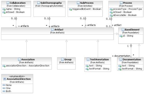
Figure 8.8 shows the Artifacts class diagram. When an Artifact is defined it is contained within a Collaboration or a FlowElementsContainer (a Process or Choreography).
Figure 8.8 – Artifacts Metamodel
Common Artifact Definitions
The following sub clauses provide definitions that are common to all Artifacts.
Artifact Sequence Flow Connections
See “Sequence Flow Connections Rules” on page 40 for the entire set of objects and how they MAY be source or targets of a Sequence Flow.
64 |
Business Process Model and Notation (BPMN), v2.0.2 |

An Artifact MUST NOT be a target for a Sequence Flow.
An Artifact MUST NOT be a source for a Sequence Flow.
Artifact Message Flow Connections
See “Message Flow Connection Rules” on page 41 for the entire set of objects and how they MAY be source or targets of a Message Flow.
An Artifact MUST NOT be a target for a Message Flow. An Artifact MUST NOT be a source for a Message Flow.
Association
An Association is used to associate information and Artifacts with Flow Objects. Text and graphical non-Flow Objects can be associated with the Flow Objects and Flow. An Association is also used to show the Activity used for compensation. More information about compensation can be found on page 300.
An Association is line that MUST be drawn with a dotted single line (see Figure 8.9).
The use of text, color, size, and lines for an Association MUST follow the rules defined in “Use of Text, Color, Size, and Lines in a Diagram” on page 39.
Figure 8.9 – An Association
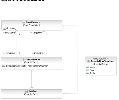
Figure 8.10 – The Association Class Diagram
If there is a reason to put directionality on the Association then:
A line arrowhead MAY be added to the Association line (see Figure 8.11).
The directionality of the Association can be in one (1) direction or in both directions.
Business Process Model and Notation (BPMN), v2.0.2 |
65 |

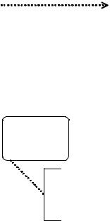
Figure 8.11 – A Directional Association
Note that directional Associations were used in BPMN 1.2 to show how Data Objects were inputs or outputs to Activities. In BPMN 2.0.2, a Data Association connector is used to show inputs and outputs (see page 220). A Data Association uses the same notation as a directed Association (as in Figure 8.11, above).
An Association is used to connect user-defined text (an Annotation) with a Flow Object (see Figure 8.12).
Announce
Issues for
Discussion
Allow 1 week for the discussion of the Issues — through e- mail or calls
Figure 8.12 – An Association of Text Annotation
The Association element inherits the attributes and model associations of BaseElement (see Table 8.5). Table 8.20 presents the additional attributes and model associations for an Association.
Table 8.20 – Association attributes and model associations
Attributes |
Description |
|
|
associationDirection: |
associationDirection is an attribute that defines whether or not the |
AssociationDirection = None {None | |
Association shows any directionality with an arrowhead. The default is |
One | Both} |
None (no arrowhead). A value of One means that the arrowhead SHALL |
|
be at the Target Object. A value of Both means that there SHALL be an |
|
arrowhead at both ends of the Association line. |
|
|
sourceRef: BaseElement |
The BaseElement that the Association is connecting from. |
targetRef: BaseElement |
The BaseElement that the Association is connecting to. |
Group
The Group object is an Artifact that provides a visual mechanism to group elements of a diagram informally. The grouping is tied to the CategoryValue supporting element. That is, a Group is a visual depiction of a single CategoryValue. The graphical elements within the Group will be assigned the CategoryValue of the Group. (NOTE - CategoryValues can be highlighted through other mechanisms, such as color, as defined by a modeler or a modeling tool).
A Group is a rounded corner rectangle that MUST be drawn with a solid dashed line (as seen in Figure 8.13).
66 |
Business Process Model and Notation (BPMN), v2.0.2 |

The use of text, color, size, and lines for a Group MUST follow the rules defined in “Use of Text, Color, Size, and Lines in a Diagram” on page 39.
Figure 8.13 – A Group Artifact
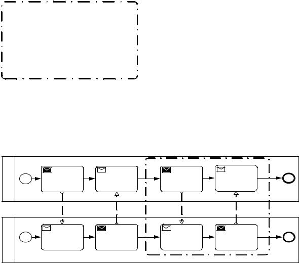
As an Artifact, a Group is not an Activity or any Flow Object, and, therefore, cannot connect to Sequence Flows or Message Flows. In addition, Groups are not constrained by restrictions of Pools and Lanes. This means that a Group can stretch across the boundaries of a Pool to surround Diagram elements (see Figure 8.14), often to identify Activities that exist within a distributed business-to-business transaction.
|
|
|
|
H andle M edicine |
|
Patient |
|
Send D octor |
R eceive |
S end |
R eceive |
|
M edicine |
||||
|
R equest |
Appt. |
M edicine |
||
Illness |
R equest |
||||
|
O ccurs |
|
|
|
|
|
|
I w ant to see doctor |
G o see doctor |
I need m y m edicine |
H ere is your m edicine |
Receptionist |
R eceive |
|
R eceive |
Send |
|
D octor |
Send A ppt. |
D octor |
|||
M edicine |
|||||
R equest |
|
R equest |
|||
|
|
||||
|
|
|
|
Figure 8.14 – A Group around Activities in different Pools
Groups are often used to highlight certain sub clauses of a Diagram without adding additional constraints for performance, as a Sub-Process would. The highlighted (grouped) sub clause of the Diagram can be separated for reporting and analysis purposes. Groups do not affect the flow of the Process.
Figure 8.15 shows the Group class diagram.
Business Process Model and Notation (BPMN), v2.0.2 |
67 |