

- •1 Scope
- •1.1 General
- •2 Conformance
- •2.1 General
- •2.2 Process Modeling Conformance
- •2.2.1 BPMN Process Types
- •2.2.2 BPMN Process Elements
- •Descriptive Conformance Sub-Class
- •Analytic Conformance Sub-Class
- •Common Executable Conformance Sub-Class
- •2.2.3 Visual Appearance
- •2.2.4 Structural Conformance
- •2.2.5 Process Semantics
- •2.2.6 Attributes and Model Associations
- •2.2.7 Extended and Optional Elements
- •2.2.8 Visual Interchange
- •2.3 Process Execution Conformance
- •2.3.1 Execution Semantics
- •2.3.2 Import of Process Diagrams
- •2.4 BPEL Process Execution Conformance
- •2.5 Choreography Modeling Conformance
- •2.5.1 BPMN Choreography Types
- •2.5.2 BPMN Choreography Elements
- •2.5.3 Visual Appearance
- •2.5.4 Choreography Semantics
- •2.5.5 Visual Interchange
- •2.6 Summary of BPMN Conformance Types
- •3 Normative References
- •3.1 General
- •3.2 Normative
- •3.3 Non-Normative
- •Activity Service
- •BPEL4People
- •Business Process Definition Metamodel
- •Business Process Modeling
- •Business Transaction Protocol
- •Dublin Core Meta Data
- •ebXML BPSS
- •Open Nested Transactions
- •SOAP 1.2
- •UDDI
- •WfMC Glossary
- •Web Services Transaction
- •Workflow Patterns
- •WSBPEL
- •WS-Coordination
- •WSDL
- •WS-HumanTask
- •XML 1.0 (Second Edition)
- •XML-Namespaces
- •XML-Schema
- •XPath
- •XPDL
- •4 Terms and Definitions
- •5 Symbols
- •6 Additional Information
- •6.1 Conventions
- •6.1.1 Typographical and Linguistic Conventions and Style
- •6.1.2 Abbreviations
- •6.2 Structure of this Document
- •6.3 Acknowledgments
- •Submitting Organizations
- •Supporting Organizations
- •Special Acknowledgments
- •7 Overview
- •7.1 General
- •7.2 BPMN Scope
- •7.2.1 Uses of BPMN
- •Private (Internal) Business Processes
- •Public Processes
- •Collaborations
- •Choreographies
- •Conversations
- •Diagram Point of View
- •Understanding the Behavior of Diagrams
- •7.3 BPMN Elements
- •7.3.1 Basic BPMN Modeling Elements
- •7.3.2 Extended BPMN Modeling Elements
- •7.4 BPMN Diagram Types
- •7.5 Use of Text, Color, Size, and Lines in a Diagram
- •7.6 Flow Object Connection Rules
- •7.6.1 Sequence Flow Connections Rules
- •7.6.2 Message Flow Connection Rules
- •7.7 BPMN Extensibility
- •7.8 BPMN Example
- •8 BPMN Core Structure
- •8.1 General
- •8.2 Infrastructure
- •8.2.1 Definitions
- •8.2.2 Import
- •8.2.3 Infrastructure Package XML Schemas
- •8.3 Foundation
- •8.3.1 Base Element
- •8.3.2 Documentation
- •8.3.3 Extensibility
- •Extension
- •ExtensionDefinition
- •ExtensionAttributeDefinition
- •ExtensionAttributeValue
- •Extensibility XML Schemas
- •XML Example
- •8.3.4 External Relationships
- •8.3.5 Root Element
- •8.3.6 Foundation Package XML Schemas
- •8.4 Common Elements
- •8.4.1 Artifacts
- •Common Artifact Definitions
- •Artifact Sequence Flow Connections
- •Artifact Message Flow Connections
- •Association
- •Group
- •Category
- •Text Annotation
- •XML Schema for Artifacts
- •8.4.2 Correlation
- •CorrelationKey
- •Key-based Correlation
- •Context-based Correlation
- •XML Schema for Correlation
- •8.4.3 Error
- •8.4.4 Escalation
- •8.4.5 Events
- •8.4.6 Expressions
- •Expression
- •Formal Expression
- •8.4.7 Flow Element
- •8.4.8 Flow Elements Container
- •8.4.9 Gateways
- •8.4.10 Item Definition
- •8.4.11 Message
- •8.4.12 Resources
- •8.4.13 Sequence Flow
- •Flow Node
- •8.4.14 Common Package XML Schemas
- •8.5 Services
- •8.5.1 Interface
- •8.5.2 EndPoint
- •8.5.3 Operation
- •8.5.4 Service Package XML Schemas
- •9 Collaboration
- •9.1 General
- •9.2 Basic Collaboration Concepts
- •9.2.1 Use of BPMN Common Elements
- •9.3 Pool and Participant
- •9.3.1 Participants
- •PartnerEntity
- •PartnerRole
- •Participant Multiplicity
- •ParticipantAssociation
- •9.3.2 Lanes
- •9.4 Message Flow
- •9.4.1 Interaction Node
- •9.4.2 Message Flow Associations
- •9.5 Conversations
- •9.5.1 Conversation Node
- •9.5.2 Conversation
- •9.5.3 Sub-Conversation
- •9.5.4 Call Conversation
- •9.5.5 Global Conversation
- •9.5.6 Conversation Link
- •9.5.7 Conversation Association
- •9.5.8 Correlations
- •9.6 Process within Collaboration
- •9.7 Choreography within Collaboration
- •9.8 Collaboration Package XML Schemas
- •10 Process
- •10.1 General
- •10.2 Basic Process Concepts
- •10.2.1 Types of BPMN Processes
- •10.2.2 Use of BPMN Common Elements
- •10.3 Activities
- •Sequence Flow Connections
- •Message Flow Connections
- •10.3.1 Resource Assignment
- •Resource Role
- •Expression Assignment
- •Parameterized Resource Assignment
- •10.3.2 Performer
- •10.3.3 Tasks
- •Service Task
- •Send Task
- •Receive Task
- •User Task
- •Manual Task
- •Business Rule
- •Script Task
- •10.3.4 Human Interactions
- •Notation
- •Manual Task
- •User Task
- •Rendering of User Tasks
- •Human Performers
- •Potential Owners
- •XML Schema for Human Interactions
- •Examples
- •10.3.5 Sub-Processes
- •Embedded Sub-Process (Sub-Process)
- •Reusable Sub-Process (Call Activity)
- •Event Sub-Process
- •Transaction
- •Ad-Hoc Sub-Process
- •10.3.6 Call Activity
- •Callable Element
- •10.3.7 Global Task
- •Types of Global Task
- •10.3.8 Loop Characteristics
- •Standard Loop Characteristics
- •Multi-Instance Characteristics
- •Complex Behavior Definition
- •10.3.9 XML Schema for Activities
- •10.4 Items and Data
- •10.4.1 Data Modeling
- •Item-Aware Elements
- •Data Objects
- •DataObject
- •States
- •Data Objects representing a Collection of Data
- •Visual representations of Data Objects
- •Lifecycle and Accessibility
- •Data Stores
- •Properties
- •Lifecycle and Accessibility
- •Data Inputs and Outputs
- •Data Input
- •States
- •Data Output
- •States
- •Service Task Mapping
- •Send Task Mapping
- •Receive Task Mapping
- •User Task Mapping
- •Call Activity Mapping
- •Script Task Mapping
- •Events
- •InputSet
- •OutputSet
- •Data Associations
- •DataAssociation
- •Assignment
- •DataInputAssociation
- •DataOutputAssociation
- •Data Objects associated with a Sequence Flow
- •10.4.2 Execution Semantics for Data
- •Execution Semantics for DataAssociation
- •10.4.3 Usage of Data in XPath Expressions
- •Access to BPMN Data Objects
- •Access to BPMN Data Input and Data Output
- •Access to BPMN Properties
- •For BPMN Instance Attributes
- •10.4.4 XML Schema for Data
- •10.5 Events
- •10.5.1 Concepts
- •Data Modeling and Events
- •Common Event attributes
- •Common Catch Event attributes
- •Common Throw Event Attributes
- •Implicit Throw Event
- •10.5.2 Start Event
- •Start Event Triggers
- •Start Events for Top-level Processes
- •Start Events for Sub-Processes
- •Start Events for Event Sub-Processes
- •Attributes for Start Events
- •Sequence Flow Connections
- •Message Flow Connections
- •10.5.3 End Event
- •End Event Results
- •Sequence Flow Connections
- •Message Flow Connections
- •10.5.4 Intermediate Event
- •Intermediate Event Triggers
- •Intermediate Events in Normal Flow
- •Intermediate Events Attached to an Activity Boundary
- •Attributes for Boundary Events
- •Activity Boundary Connections
- •Sequence Flow Connections
- •Message Flow Connections
- •10.5.5 Event Definitions
- •Event Definition Metamodel
- •Cancel Event
- •Compensation Event
- •Conditional Event
- •Error Event
- •Escalation Event Definition
- •Link Event Definition
- •Message Event Definition
- •Multiple Event
- •None Event
- •Parallel Multiple Event
- •Signal Event
- •Terminate Event
- •Timer Event
- •10.5.6 Handling Events
- •Handling Start Events
- •Handling Events within normal Sequence Flow (Intermediate Events)
- •Handling Events attached to an Activity (Intermediate boundary Events and Event Sub-Processes)
- •Interrupting Event Handlers (Error, Escalation, Message, Signal, Timer, Conditional, Multiple, and Parallel Multiple)
- •Non-interrupting Event Handlers (Escalation, Message, Signal, Timer, Conditional, Multiple, and Parallel Multiple)
- •Handling End Events
- •10.5.7 Scopes
- •10.5.8 Events Package XML Schemas
- •10.6 Gateways
- •10.6.1 Sequence Flow Considerations
- •10.6.2 Exclusive Gateway
- •10.6.3 Inclusive Gateway
- •10.6.4 Parallel Gateway
- •10.6.5 Complex Gateway
- •10.6.6 Event-Based Gateway
- •10.6.7 Gateway Package XML Schemas
- •10.7 Compensation
- •10.7.1 Compensation Handler
- •10.7.2 Compensation Triggering
- •10.7.3 Relationship between Error Handling and Compensation
- •10.8 Lanes
- •10.9 Process Instances, Unmodeled Activities, and Public Processes
- •10.10 Auditing
- •10.11 Monitoring
- •10.12 Process Package XML Schemas
- •11 Choreography
- •11.1 General
- •11.2 Basic Choreography Concepts
- •11.3 Data
- •11.4 Use of BPMN Common Elements
- •11.4.1 Sequence Flow
- •11.4.2 Artifacts
- •11.5 Choreography Activities
- •11.5.1 Choreography Task
- •11.5.2 Sub-Choreography
- •The Parent Sub-Choreography (Expanded)
- •11.5.3 Call Choreography
- •11.5.4 Global Choreography Task
- •11.5.5 Looping Activities
- •11.5.6 The Sequencing of Activities
- •11.6 Events
- •11.6.1 Start Events
- •11.6.2 Intermediate Events
- •11.6.3 End Events
- •11.7 Gateways
- •11.7.1 Exclusive Gateway
- •11.7.2 Event-Based Gateway
- •11.7.3 Inclusive Gateway
- •11.7.4 Parallel Gateway
- •11.7.5 Complex Gateway
- •11.7.6 Chaining Gateways
- •11.8 Choreography within Collaboration
- •11.8.1 Participants
- •11.8.2 Swimlanes
- •Choreography Task in Combined View
- •Sub-Choreography in Combined View
- •11.9 XML Schema for Choreography
- •12 BPMN Notation and Diagrams
- •12.1 BPMN Diagram Interchange (BPMN DI)
- •12.1.1 Scope
- •12.1.2 Diagram Definition and Interchange
- •12.1.3 How to Read this Clause
- •12.2 BPMN Diagram Interchange (DI) Meta-model
- •12.2.1 Overview
- •12.2.2 Abstract Syntax
- •12.2.3 Classifier Descriptions
- •12.2.4 Complete BPMN DI XML Schema
- •12.3 Notational Depiction Library and Abstract Element Resolutions
- •12.3.1 Labels
- •12.3.2 BPMNShape
- •Markers for Activities
- •Tasks [BPMNShape]
- •Collapsed Sub-Processes [BPMNShape]
- •Expanded Sub-Processes [BPMNShape]
- •Collapsed Ad Hoc Sub-Processes [BPMNShape]
- •Expanded Ad Hoc Sub-Processes [BPMNShape]
- •Collapsed Transactions [BPMNShape]
- •Expanded Transactions [BPMNShape]
- •Collapsed Event Sub-Processes [BPMNShape]
- •Expanded Event Sub-Processes [BPMNShape]
- •Call Activities (Calling a Global Task) [BPMNShape]
- •Collapsed Call Activities (Calling a Process) [BPMNShape]
- •Expanded Call Activities (Calling a Process) [BPMNShape]
- •Data [BPMNShape]
- •Events [BPMNShape]
- •Gateways [BPMNShape]
- •Artifacts [BPMNShape]
- •Lanes [BPMNShape]
- •Pools [BPMNShape]
- •Choreography Tasks [BPMNShape]
- •Collapsed Sub-Choreographies [BPMNShape]
- •Expanded Sub-Choreographies [BPMNShape]
- •Call Choreographies (Calling a Global Choreography Task) [BPMNShape]
- •Collapsed Call Choreographies (Calling a Choreography) [BPMNShape]
- •Expanded Call Choreographies (Calling a Choreography) [BPMNShape]
- •Choreography Participant Bands [BPMNShape]
- •Conversations [BPMNShape]
- •12.3.3 BPMNEdge
- •Connecting Objects [BPMNEdge]
- •12.4 Example(s)
- •12.4.1 Depicting Content in a Sub-Process
- •Expanded Sub-Process
- •Expanded Sub-Process with Start and End Events on Border
- •Collapsed Sub-Process
- •12.4.2 Multiple Lanes and Nested Lanes
- •12.4.3 Vertical Collaboration
- •12.4.4 Conversation
- •12.4.5 Choreography
- •13 BPMN Execution Semantics
- •13.1 General
- •13.2 Process Instantiation and Termination
- •13.3 Activities
- •13.3.1 Sequence Flow Considerations
- •13.3.2 Activity
- •13.3.3 Task
- •13.3.4 Sub-Process/Call Activity
- •13.3.5 Ad-Hoc Sub-Process
- •Operational semantics
- •13.3.6 Loop Activity
- •13.3.7 Multiple Instances Activity
- •13.4 Gateways
- •13.4.1 Parallel Gateway (Fork and Join)
- •13.4.2 Exclusive Gateway (Exclusive Decision (data-based) and Exclusive Merge)
- •13.4.3 Inclusive Gateway (Inclusive Decision and Inclusive Merge)
- •13.4.4 Event-based Gateway (Exclusive Decision (event-based))
- •13.4.5 Complex Gateway (related to Complex Condition and Complex Merge)
- •13.5 Events
- •13.5.1 Start Events
- •13.5.2 Intermediate Events
- •13.5.3 Intermediate Boundary Events
- •13.5.4 Event Sub-Processes
- •Operational semantics
- •13.5.5 Compensation
- •Compensation Handler
- •Compensation Triggering
- •Relationship between Error Handling and Compensation
- •Operational Semantics
- •13.5.6 End Events
- •Process level end events
- •Sub-process level end events
- •14 Mapping BPMN Models to WS-BPEL
- •14.1 General
- •14.2 Basic BPMN-BPEL Mapping
- •14.2.1 Process
- •14.2.2 Activities
- •Common Activity Mappings
- •Task Mappings
- •Service Task
- •Receive Task
- •Send Task
- •Abstract Task
- •Service Package
- •Message
- •Interface and Operation
- •Conversations and Correlation
- •Sub-Process Mappings
- •Mapping of Event Sub-Processes
- •Activity Loop Mapping
- •Standard Loops
- •Dealing with LoopMaximum
- •Multi-Instance Activities
- •14.2.3 Events
- •Start Event Mappings
- •Message Start Events
- •Error Start Events
- •Compensation Start Events
- •Intermediate Event Mappings (Non-boundary)
- •Message Intermediate Events (Non-boundary)
- •Timer Intermediate Events (Non-boundary)
- •Compensation Intermediate Events (Non-boundary)
- •End Event Mappings
- •None End Events
- •Message End Events
- •Error End Events
- •Compensation End Events
- •Terminate End Events
- •Boundary Intermediate Events
- •Message Boundary Events
- •Error Boundary Events
- •Compensation Boundary Events
- •Multiple Boundary Events, and Boundary Events with Loops
- •14.2.4 Gateways and Sequence Flows
- •Exclusive (Data-based) Decision Pattern
- •Exclusive (Event-based) Decision Pattern
- •Inclusive Decision Pattern
- •Parallel Pattern
- •Sequence Pattern
- •Structured Loop Patterns
- •Handling Loops in Sequence Flows
- •14.2.5 Handling Data
- •Data Objects
- •Properties
- •Input and Output Sets
- •Data Associations
- •Expressions
- •Assignments
- •14.3 Extended BPMN-BPEL Mapping
- •14.3.1 End Events
- •14.3.2 Loop/Switch Combinations From a Gateway
- •14.3.3 Interleaved Loops
- •14.3.4 Infinite Loops
- •14.3.5 BPMN Elements that Span Multiple WSBPEL Sub-Elements
- •15 Exchange Formats
- •15.1 Interchanging Incomplete Models
- •15.2 Machine Readable Files
- •15.3.1 Document Structure
- •15.3.2 References within the BPMN XSD
- •15.5 XSLT Transformation between XSD and XMI
- •B.1 Scope
- •B.2 Architecture
- •B.3 Diagram Common
- •B.3.1 Overview
- •B.3.2 Abstract Syntax
- •B.3.3 Classifier Descriptions
- •B.4 Diagram Interchange
- •B.4.1 Overview
- •B.4.2 Abstract Syntax
- •B.4.3 Classifier Descriptions

</xsd:complexContent> </xsd:complexType>
10.6 Gateways
Gateways are used to control how Sequence Flows interact as they converge and diverge within a Process. If the flow does not need to be controlled, then a Gateway is not needed. The term “Gateway” implies that there is a gating mechanism that either allows or disallows passage through the Gateway. As tokens arrive at a Gateway they can be merged together on input and/or split apart on output as the Gateway mechanisms are invoked.
A Gateway is a diamond, which has been used in many flow chart notations for exclusive branching and is familiar to most modelers.
A Gateway is a diamond that MUST be drawn with a single thin line (see Figure 10.102).
Figure 10.102 – A Gateway
The use of text, color, size, and lines for a Gateway MUST follow the rules defined in “Use of Text, Color, Size, and Lines in a Diagram” on page 39 with the exception that:
Gateways, like Activities, are capable of consuming or generating additional tokens, effectively controlling the execution semantics of a given Process. The main difference is that Gateways do not represent ‘work’ being done and they are considered to have zero effect on the operational measures of the Process being executed (cost, time, etc.).
Gateways can define all the types of Business Process Sequence Flow behavior: Decisions/branching (exclusive, inclusive, and complex), merging, forking, and joining. Thus, while the diamond has been used traditionally for exclusive decisions, BPMN extends the behavior of the diamonds to reflect any type of Sequence Flow control. Each type of Gateway will have an internal indicator or marker to show the type of Gateway that is being used (see Figure 10.103).
286 |
Business Process Model and Notation (BPMN), v2.0.2 |

Exclusive |
or |
X |
|
||
Event-Based |
|
|
Parallel
Event-Based
Inclusive
Complex
Parallel
Figure 10.103 – The Different types of Gateways
The Gateway controls the flow of both diverging and converging Sequence Flows. That is, a single Gateway could have multiple input and multiple output flows. Modelers and modeling tools might want to enforce a best practice of a Gateway only performing one of these functions. Thus, it would take two sequential Gateways to first converge and then to diverge the Sequence Flows.
Business Process Model and Notation (BPMN), v2.0.2 |
287 |
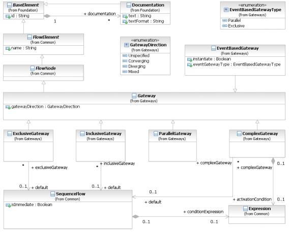
Figure 10.104 – Gateway class diagram
Gateways are described in this sub clause on an abstract level. The execution semantics of Gateways is detailed on page 434.
10.6.1 Sequence Flow Considerations
NOTE: Although the shape of a Gateway is a diamond, it is not a requirement that incoming and outgoing Sequence Flows MUST connect to the corners of the diamond. Sequence Flows can connect to any position on the boundary of the Gateway shape.
This sub clause applies to all Gateways. Additional Sequence Flow Connection rules are specified for each type of Gateway in the sub clauses below.
A Gateway MAY be a target for a Sequence Flow. It can have zero (0), one (1), or more incoming
Sequence Flows.
If the Gateway does not have an incoming Sequence Flow, and there is no Start Event for the Process, then the Gateway’s divergence behavior, depending on the type of Gateway (see below), SHALL be performed when the Process is instantiated.
288 |
Business Process Model and Notation (BPMN), v2.0.2 |
A Gateway MAY be a source of a Sequence Flow; it can have zero, one, or more outgoing Sequence Flows.
A Gateway MUST have either multiple incoming Sequence Flows or multiple outgoing Sequence Flows (i.e., it MUST merge or split the flow).
A Gateway with a gatewayDirection of unspecified MAY have both multiple incoming and outgoing Sequence Flows.
A Gateway with a gatewayDirection of mixed MUST have both multiple incoming and outgoing
Sequence Flows.
A Gateway with a gatewayDirection of converging MUST have multiple incoming Sequence Flows, but MUST NOT have multiple outgoing Sequence Flows.
A Gateway with a gatewayDirection of diverging MUST have multiple outgoing Sequence Flows, but MUST NOT have multiple incoming Sequence Flows.
10.6.2 Exclusive Gateway
A diverging Exclusive Gateway (Decision) is used to create alternative paths within a Process flow. This is basically the “diversion point in the road” for a Process. For a given instance of the Process, only one of the paths can be taken.
A Decision can be thought of as a question that is asked at a particular point in the Process. The question has a defined set of alternative answers. Each answer is associated with a condition Expression that is associated with a Gateway’s outgoing Sequence Flows.
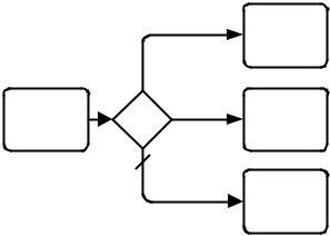
The Exclusive Gateway MAY use a marker that is shaped like an “X” and is placed within the Gateway diamond (see Figure 10.106) to distinguish it from other Gateways. This marker is NOT REQUIRED (see Figure 10.105).
A diagram SHOULD be consistent in the use of the “X” internal indicator. That is, a diagram SHOULD NOT have some Gateways with an indicator and other Gateways without an indicator.
Condition 1
Condition 2
Default
Figure 10.105 – An Exclusive Data-Based Decision (Gateway) Example without the Internal Indicator
Business Process Model and Notation (BPMN), v2.0.2 |
289 |
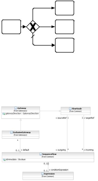
Condition 1
Condition 2
Default
Figure 10.106 – A Data-Based Exclusive Decision (Gateway) Example with the Internal Indicator
NOTE: as a modeling preference, the Exclusive Gateways shown in examples within this document will be shown without the internal indicator.
A default path can optionally be identified, to be taken in the event that none of the conditional Expressions evaluate to true. If a default path is not specified and the Process is executed such that none of the conditional Expressions evaluates to true, a runtime exception occurs.
A converging Exclusive Gateway is used to merge alternative paths. Each incoming Sequence Flow token is routed to the outgoing Sequence Flow without synchronization.
Figure 10.107 – Exclusive Gateway class diagram
The Exclusive Gateway element inherits the attributes and model associations of Gateway (see Table 8.46). Table 10.123 presents the additional attributes and model associations of the Exclusive Gateway element.
290 |
Business Process Model and Notation (BPMN), v2.0.2 |