

view the status of the Activities or troubleshoot any problems. However, the Diagram itself remains the same. Figure 7.3 displays a Business Process that has two points of view. One point of view is of a Patient, the other is of the Doctor’s office. The Diagram shows the Activities of both participants in the Process, but when the Process is actually being performed, each Participant will only have control over their own Activities. Although the Diagram point of view is important for a viewer of the Diagram to understand how the behavior of the Process will relate to that viewer, BPMN will not currently specify any graphical mechanisms to highlight the point of view. It is open to the modeler or modeling tool vendor to provide any visual cues to emphasize this characteristic of a Diagram.
Understanding the Behavior of Diagrams
Throughout this International Standard, we discuss how Sequence Flows are used within a Process. To facilitate this discussion, we employ the concept of a token that will traverse the Sequence Flows and pass through the elements in the Process. A token is a theoretical concept that is used as an aid to define the behavior of a Process that is being performed. The behavior of Process elements can be defined by describing how they interact with a token as it “traverses” the structure of the Process. However, modeling and execution tools that implement BPMN are NOT REQUIRED to implement any form of token.
A Start Event generates a token that MUST eventually be consumed at an End Event (which MAY be implicit if not graphically displayed). The path of tokens should be traceable through the network of Sequence Flows, Gateways, and
Activities within a Process.
NOTE: A token does not traverse a Message Flow since it is a Message that is passed down a Message Flow (as the name implies).
7.3BPMN Elements
It should be emphasized that one of the drivers for the development of BPMN is to create a simple and understandable mechanism for creating Business Process models, while at the same time being able to handle the complexity inherent to Business Processes. The approach taken to handle these two conflicting requirements was to organize the graphical aspects of the notation into specific categories. This provides a small set of notation categories so that the reader of a BPMN diagram can easily recognize the basic types of elements and understand the diagram. Within the basic categories of elements, additional variation and information can be added to support the requirements for complexity without dramatically changing the basic look and feel of the diagram. The five basic categories of elements are:
1.Flow Objects
2.Data
3.Connecting Objects
4.Swimlanes
5.Artifacts
Flow Objects are the main graphical elements to define the behavior of a Business Process. There are three Flow Objects:
1.Events
2.Activities
3.Gateways
Data is represented with the four elements:
Business Process Model and Notation (BPMN), v2.0.2 |
25 |

1.Data Objects
2.Data Inputs
3.Data Outputs
4.Data Stores
There are four ways of connecting the Flow Objects to each other or other information. There are four Connecting Objects:
1.Sequence Flows
2.Message Flows
3.Associations
4.Data Associations
There are two ways of grouping the primary modeling elements through “Swimlanes:”
1.Pools
2.Lanes
Artifacts are used to provide additional information about the Process. There are two standardized Artifacts, but modelers or modeling tools are free to add as many Artifacts as necessary. There could be additional BPMN efforts to standardize a larger set of Artifacts for general use or for vertical markets. The current set of Artifacts includes:
•Group
•Text Annotation
7.3.1Basic BPMN Modeling Elements
Table 7.1 displays a list of the basic modeling elements that are depicted by the notation.
Table 7.1 – Basic Modeling Elements
Element |
Description |
Notation |
|
|
|
Event |
An Event is something that “happens” during the |
|
|
course of a Process (see page 235) or a |
|
|
Choreography (see page 339). These Events |
|
|
affect the flow of the model and usually have a |
|
|
cause (trigger) or an impact (result). Events are |
|
|
circles with open centers to allow internal markers |
|
|
to differentiate different triggers or results. There |
|
|
are three types of Events, based on when they |
|
|
affect the flow: Start, Intermediate, and End. |
|
Activity |
An Activity is a generic term for work that company |
|
|
performs (see page 149) in a Process. An Activity |
|
|
can be atomic or non-atomic (compound). The |
|
|
types of Activities that are a part of a Process |
|
|
Model are: Sub-Process and Task, which are |
|
|
rounded rectangles. Activities are used in both |
|
|
standard Processes and in Choreographies. |
|
|
|
|
26 |
Business Process Model and Notation (BPMN), v2.0.2 |
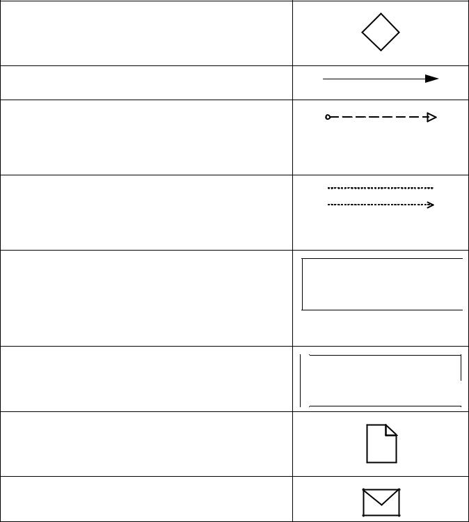
Table 7.1 – Basic Modeling Elements
Gateway |
A Gateway is used to control the divergence and |
|
convergence of Sequence Flows in a Process |
|
(see page 147) and in a Choreography (see page |
|
335). Thus, it will determine branching, forking, |
|
merging, and joining of paths. Internal markers will |
|
indicate the type of behavior control. |
Sequence Flow |
A Sequence Flow is used to show the order that |
|
Activities will be performed in a Process (see page |
|
95) and in a Choreography (see page 320). |
Message Flow |
A Message Flow is used to show the flow of |
|
Messages between two Participants that are |
|
prepared to send and receive them (see page |
|
113). In BPMN, two separate Pools in a |
|
Collaboration Diagram will represent the two |
|
Participants (e.g., PartnerEntities and/or |
|
PartnerRoles). |
Association |
An Association is used to link information and |
|
Artifacts with BPMN graphical elements (see page |
|
65). Text Annotations (see page 69) and other |
|
Artifacts (see page 64) can be Associated with the |
|
graphical elements. An arrowhead on the |
|
Association indicates a direction of flow (e.g., |
|
data), when appropriate. |
Pool |
A Pool is the graphical representation of a |
|
Participant in a Collaboration (see page 113). It |
|
also acts as a “swimlane” and a graphical |
|
container for partitioning a set of Activities from |
|
other Pools, usually in the context of B2B |
|
situations. A Pool MAY have internal details, in the |
|
form of the Process that will be executed. Or a |
|
Pool MAY have no internal details, i.e., it can be a |
|
“black box.” |
Lane |
A Lane is a sub-partition within a Process, |
|
sometimes within a Pool, and will extend the entire |
|
length of the Process, either vertically or |
|
horizontally (see on page 304). Lanes are used to |
|
organize and categorize Activities. |
Data Object |
Data Objects provide information about what |
|
Activities require to be performed and/or what they |
|
produce (see page 204), Data Objects can |
|
represent a singular object or a collection of |
|
objects. Data Input and Data Output provide the |
|
same information for Processes. |
Message |
A Message is used to depict the contents of a |
|
communication between two Participants (as |
|
defined by a business PartnerRole or a business |
|
PartnerEntity—see on page 91). |
|
|
Name
Name Name
Name
Business Process Model and Notation (BPMN), v2.0.2 |
27 |
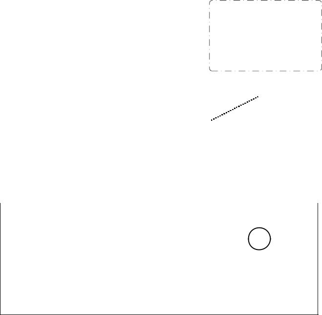
Table 7.1 – Basic Modeling Elements
Group (a box around a |
A Group is a grouping of graphical elements that |
|
|
|
group of objects within |
are within the same Category (see page 68). This |
|
|
|
the same category) |
type of grouping does not affect the Sequence |
|
|
|
|
Flows within the Group. The Category name |
|
|
|
|
appears on the diagram as the group label. |
|
|
|
|
Categories can be used for documentation or |
|
|
|
|
analysis purposes. Groups are one way in which |
|
|
|
|
Categories of objects can be visually displayed on |
|
|
|
|
the diagram. |
|
|
|
|
|
|
|
|
Text Annotation |
Text Annotations are a mechanism for a modeler |
|
|
|
(attached with an |
to provide additional text information for the reader |
|
Descriptive Text |
|
Association) |
of a BPMN Diagram (see page 69). |
|
||
|
|
Here |
||
|
|
|
|
|
|
|
|
|
|
|
|
|
|
|
7.3.2Extended BPMN Modeling Elements
Table 7.2 displays a more extensive list of the Business Process concepts that could be depicted through a business process modeling notation.
Table 7.2 – BPMN Extended Modeling Elements
Element |
Description |
Notation |
|
|
|
Event |
An Event is something that “happens” during |
|
|
the course of a Process (see page 237) or a |
|
|
Choreography (see page 335). These Events |
|
|
affect the flow of the model and usually have |
|
|
a cause (Trigger) or an impact (Result). |
|
|
Events are circles with open centers to allow |
|
|
internal markers to differentiate different |
|
|
Triggers or Results. There are three types of |
|
|
Events, based on when they affect the flow: |
|
|
Start, Intermediate, and End. |
|
|
|
|
Flow Dimension (e.g., Start, Intermediate, End)
28 |
Business Process Model and Notation (BPMN), v2.0.2 |
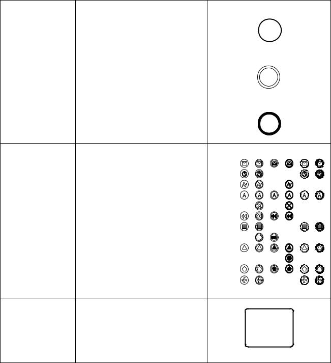
Table 7.2 – BPMN Extended Modeling Elements
Start |
As the name implies, the Start Event indicates |
Start |
|
|
where a particular Process (see page 235) or |
|
|
|
Choreography (see page 339) will start. |
|
|
Intermediate |
Intermediate Events occur between a Start |
Intermediate |
|
|
Event and an End Event. They will affect the |
||
|
|
||
|
flow of the Process (see page 237) or |
|
|
|
Choreography (see page 340), but will not |
|
|
|
start or (directly) terminate the Process. |
|
|
End |
As the name implies, the End Event indicates |
End |
|
|
|||
|
where a Process (see page 245) or |
|
|
|
Choreography (see page 343) will end. |
|
|
Type Dimension (e.g., |
The Start and some Intermediate Events have |
“Catching” “Throwing” Non-Interrupting |
|
None, Message, Timer, |
“triggers” that define the cause for the Event |
||
|
|||
Error, Cancel, |
(See “Start Event” on page 237. and |
Message |
|
Compensation, |
“Intermediate Event” on page 248). There are |
Timer |
|
Conditional, Link, Signal, |
multiple ways that these events can be |
||
Error |
|||
Multiple, Terminate.) |
triggered. End Events MAY define a “result” |
||
|
that is a consequence of a Sequence Flow |
Escalation |
|
|
path ending. Start Events can only react to |
Cancel |
|
|
(“catch”) a trigger. End Events can only create |
||
|
|
||
|
(“throw”) a result. Intermediate Events can |
Compensation |
|
|
catch or throw triggers. For the Events, |
Conditional |
|
|
triggers that catch, the markers are unfilled, |
||
|
|
||
|
and for triggers and results that throw, the |
Link |
|
|
markers are filled. |
Signal |
|
|
Additionally, some Events, which were used |
Terminate |
|
|
|
||
|
to interrupt Activities in BPMN 1.1, can now |
Multiple |
|
|
be used in a mode that does not interrupt. The |
Parallel |
|
|
boundary of these Events is dashed (see |
Multiple |
|
|
figure to the right). |
|
|
Activity |
An Activity is a generic term for work that |
|
|
|
company performs (see page 149) in a |
|
|
|
Process. An Activity can be atomic or non- |
|
|
|
atomic (compound). The types of Activities |
|
|
|
that are a part of a Process Model are: Sub- |
|
|
|
Process and Task, which are rounded |
|
|
|
rectangles. Activities are used in both |
|
|
|
standard Processes and in Choreographies. |
|
Business Process Model and Notation (BPMN), v2.0.2 |
29 |

Table 7.2 – BPMN Extended Modeling Elements |
|
|
|
|
|
|
|
|
Task (Atomic) |
A Task is an atomic Activity that is included |
|
|
|
|
|
|
|
|
within a Process (see page 154). A Task is |
|
Task |
|||||
|
used when the work in the Process is not |
|
||||||
|
broken down to a finer level of Process detail. |
|
||||||
|
|
Name |
||||||
|
|
|
||||||
|
|
|
|
|
|
|
|
|
Choreography Task |
A Choreography Task is an atomic Activity in |
|
Participant A |
|||||
|
a Choreography (see page 323). It represents |
|
||||||
|
|
|
|
|
|
|
|
|
|
a set of one (1) or more Message exchanges. |
|
Choreography |
|
|
|||
|
Each Choreography Task involves two (2) |
|
|
|
||||
|
|
Task Name |
|
|
||||
|
Participants. The name of the Choreography |
|
|
|
||||
|
|
|
|
|
|
|
|
|
|
Task and each of the Participants are all |
|
|
|
|
|
|
|
|
|
Participant B |
||||||
|
displayed in the different bands that make up |
|
||||||
|
|
|
|
|
|
|
|
|
|
the shape’s graphical notation. There are two |
|
|
|
|
|
|
|
|
(2) or more Participant Bands and one Task |
|
|
|
|
|
|
|
|
Name Band. |
|
|
|
|
|
|
|
|
|
|
|
|
|
|
|
|
Process/Sub-Process |
A Sub-Process is a compound Activity that is |
|
|
|
|
|
|
|
(non-atomic) |
included within a Process (see page 171) or |
See Next Four Figures |
||||||
|
Choreography (see page 335). It is compound |
|||||||
|
in that it can be broken down into a finer level |
|
|
|
|
|
|
|
|
of detail (a Process or Choreography) through |
|
|
|
|
|
|
|
|
a set of sub-Activities. |
|
|
|
|
|
|
|
|
|
|
|
|
|
|
|
|
Collapsed Sub-Process |
The details of the Sub-Process are not visible |
|
|
|
|
|
|
|
|
in the Diagram (see page 171). A “plus” sign |
|
|
|
|
|
|
|
|
in the lower-center of the shape indicates that |
|
Sub-Process |
|||||
|
the Activity is a Sub-Process and has a lower- |
|
||||||
|
level of detail. |
|
Name |
|||||
|
|
|
|
|
|
|
|
|
|
|
|
|
|
|
|
|
|
Expanded Sub-Process |
The boundary of the Sub-Process is |
|
|
|
|
|
|
|
|
expanded and the details (a Process) are |
|
|
|
|
|
|
|
|
visible within its boundary (see page 171). |
|
|
|
|
|
|
|
|
Note that Sequence Flows cannot cross the |
|
|
|
|
|
|
|
|
boundary of a Sub-Process. |
|
|
|
|
|
|
|
Collapsed Sub- |
The details of the Sub-Choreography are not |
|
|
|
|
|
|
Choreography |
visible in the Diagram (see page 328). A |
Participant A |
|||||
|
“plus” sign in the lower-center of the Task |
Sub- |
|||||
|
Name Band of the shape indicates that the |
Choreography |
|||||
|
Activity is a Sub-Process and has a lower- |
Name |
|||||
|
level of detail. |
||||||
|
|
|
|
|
|
|
|
|
|
|
|
|
|
|
|
|
|
Participant B |
|||||
30 |
Business Process Model and Notation (BPMN), v2.0.2 |
Table 7.2 – BPMN Extended Modeling Elements |
|
|
|
|
|
|
|
|
Expanded Sub- |
The boundary of the Sub-Choreography is |
|
|
Participant A |
||||
Choreography |
expanded and the details (a Choreography) |
|
|
|||||
|
|
Participant C |
||||||
|
are visible within its boundary (see page 328). |
Sub-Choreography Name |
|
|
|
|
||
|
Note that Sequence Flows cannot cross the |
|
|
Participant C |
|
Participant A |
||
|
boundary of a Sub-Choreography. |
|
|
Choreography |
|
Choreography |
||
|
|
|
|
Task Name |
|
Task Name |
|
|
|
|
|
|
Participant B |
|
Participant C |
||
|
|
|
|
Participant B |
|
|
|
|
|
|
|
|
|
|
|
|
|
|
|
|
|
|
|
|
|
|
|
|
|
|
|
|
|
|
|
|
|
|
|
|
|
|
|
|
|
|
|
Gateway |
A Gateway is used to control the divergence |
|
|
|
|
|
|
|
|
|
|
|
|
|
|
|
and convergence of Sequence Flows in a |
|
|
|
|
|
|
|
|
|
|
|
|
|
|
|
Process (see page 286) and in a |
|
|
|
|
|
|
|
|
|
|
|
|
|
|
|
Choreography (see page 344). Thus, it will |
|
|
|
|
|
|
|
|
|
|
|
|
|
|
|
determine branching, forking, merging, and |
|
|
|
|
|
|
|
|
|
|
|
|
|
|
|
joining of paths. Internal markers will indicate |
|
|
|
|
|
|
|
|
|
|
|
|
|
|
|
the type of behavior control (see below). |
|
|
|
|
|
|
|
|
|
|
|
|
|
|
|
|
|
|
|
|
|
|
|
|
|
|
|
|
|
|
Gateway Control Types |
Icons within the diamond shape of the |
|
|
|
|
|
|
|
|
|
|
|
|
|
|
|
Gateway will indicate the type of flow control |
|
|
|
|
|
|
|
X |
||||||
|
behavior. The types of control include: |
Exclusive |
|
or |
|||||||||||
|
• Exclusive decision and merging. Both |
|
|||||||||||||
|
Exclusive (see page 286) and Event-Based |
|
|
|
|
|
|
|
|
|
|
|
|
|
|
|
(see page 296) perform exclusive |
Event-Based |
|
|
|
|
|
|
|
|
|
|
|
||
|
decisions and merging Exclusive can be |
|
|
|
|
|
|
|
|
|
|
|
|||
|
shown with or without the “X” marker. |
|
|
|
|
|
|
|
|
|
|
|
|
|
|
|
• Event-Based and Parallel Event-based |
Parallel |
|
|
|
|
|
|
|
|
|
|
|
||
|
gateways can start a new instance of the |
|
|
|
|
|
|
|
|
|
|
|
|||
|
|
|
|
|
|
|
|
|
|
|
|
||||
|
Process. |
Event-Based |
|
|
|
|
|
|
|
|
|
|
|
||
|
|
|
|
|
|
|
|
|
|
|
|
||||
|
• Inclusive Gateway decision and merging |
|
|
|
|
|
|
|
|
|
|
|
|
|
|
|
(see page 291). |
Inclusive |
|
|
|
|
|
|
|
|
|
|
|
||
|
• Complex Gateway -- complex conditions |
|
|
|
|
|
|
|
|
|
|
|
|||
|
and situations (e.g., 3 out of 5; page 294). |
|
|
|
|
|
|
|
|
|
|
|
|
|
|
|
• Parallel Gateway forking and joining (see |
Complex |
|
|
|
|
|
|
|
|
|
|
|
||
|
|
|
|
|
|
|
|
|
|
|
|
||||
|
page 292). |
|
|
|
|
|
|
|
|
|
|
|
|||
|
|
|
|
|
|
|
|
|
|
|
|
||||
|
Each type of control affects both the incoming |
|
|
|
|
|
|
|
|
|
|
|
|
|
|
|
and outgoing flow. |
Parallel |
|
|
|
|
|
|
|
|
|
|
|
||
|
|
|
|
|
|
|
|
|
|
|
|
||||
|
|
|
|
|
|
|
|
|
|
|
|
|
|
|
|
|
|
|
|
|
|
|
|
|
|
|
|
|
|
|
|
Sequence Flow |
A Sequence Flow is used to show the order |
|
|
|
|
|
|
|
|
|
|
|
|
|
|
|
that Activities will be performed in a Process |
See next seven figures |
|
|
|
|
|
|
|
|
|
|
|
||
|
(see page 95) and in a Choreography (see |
|
|
|
|
|
|
|
|
|
|
|
|||
|
|
|
|
|
|
|
|
|
|
|
|
|
|
|
|
|
page 323). |
|
|
|
|
|
|
|
|
|
|
|
|
|
|
Business Process Model and Notation (BPMN), v2.0.2 |
31 |

Table 7.2 – BPMN Extended Modeling Elements
Normal Flow |
Normal flow refers to paths of Sequence Flow |
||
|
that do not start from an Intermediate Event |
||
|
attached to the boundary of an Activity. |
|
|
|
|
||
|
|
|
|
Uncontrolled flow |
Uncontrolled flow refers to flow that is not |
||
|
affected by any conditions or does not pass |
||
|
through a Gateway. The simplest example of |
|
|
|
this is a single Sequence Flow connecting two |
||
|
Activities. This can also apply to multiple |
||
|
Sequence Flows that converge to or diverge |
||
|
from an Activity. For each uncontrolled |
||
|
Sequence Flows a token will flow from the |
||
|
source object through the Sequence Flows |
||
|
to the target object. |
||
|
|
|
|
Conditional flow |
A Sequence Flow can have a condition |
||
|
Expression that are evaluated at runtime to |
||
|
determine whether or not the Sequence Flow |
||
|
will be used (i.e., will a token travel down the |
||
|
Sequence Flow – see page 95). If the |
||
|
conditional flow is outgoing from an Activity, |
||
|
then the Sequence Flow will have a mini- |
||
|
diamond at the beginning of the connector |
||
|
(see figure to the right). If the conditional flow |
||
|
is outgoing from a Gateway, then the line will |
||
|
not have a mini-diamond (see figure in the |
||
|
row above). |
||
|
|
|
|
Default flow |
For Data-Based Exclusive Gateways or |
||
|
Inclusive Gateways, one type of flow is the |
||
|
Default condition flow (see page 95). This flow |
||
|
will be used only if all the other outgoing |
||
|
conditional flow is not true at runtime. These |
||
|
Sequence Flows will have a diagonal slash |
||
|
will be added to the beginning of the |
||
|
connector (see the figure to the right). |
||
|
|
|
|
Exception Flow |
Exception flow occurs outside the normal flow |
||
|
of the Process and is based upon an |
||
|
Intermediate Event attached to the boundary |
||
|
of an Activity that occurs during the |
||
|
performance of the Process (see page 286). |
||
Exception
Flow
Message Flow |
A Message Flow is used to show the flow of |
|
Messages between two Participants that are |
|
prepared to send and receive them (see page |
|
122). In BPMN, two separate Pools in a |
|
Collaboration Diagram will represent the two |
|
Participants (e.g., PartnerEntities and/or |
|
PartnerRoles). |
32 |
Business Process Model and Notation (BPMN), v2.0.2 |
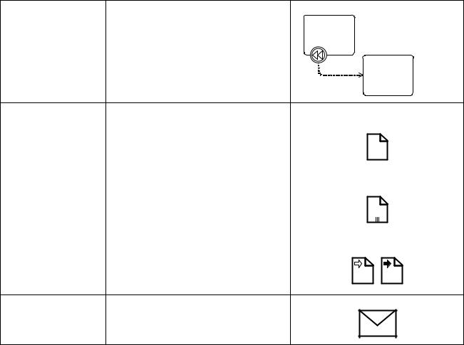
Table 7.2 – BPMN Extended Modeling Elements
Compensation |
Compensation Association occurs outside the |
|
Association |
normal flow of the Process and is based upon |
|
|
a Compensation Intermediate Event that is |
|
|
triggered through the failure of a transaction |
|
|
or a throw Compensation Event (see page |
|
|
302). The target of the Association MUST be |
|
|
marked as a Compensation Activity. |
Compensation |
|
|
Association |
Data Object |
Data Objects provide information about what |
Data Object |
|
Activities require to be performed and/or what |
|
|
they produce (see page 204), Data Objects |
|
|
can represent a singular object or a collection |
|
|
of objects. Data Input and Data Output |
|
|
provide the same information for Processes. |
|
Data Object (Collection)
Data Input |
Data Output |
Message |
A Message is used to depict the contents of a |
|
communication between two Participants (as |
|
defined by a business PartnerRole or a |
|
business PartnerEntity—see on page 91). |
Business Process Model and Notation (BPMN), v2.0.2 |
33 |

Table 7.2 – BPMN Extended Modeling Elements
Fork |
BPMN uses the term “fork” to refer to the |
|
dividing of a path into two or more parallel |
|
paths (also known as an AND-Split). It is a |
|
place in the Process where activities can be |
|
performed concurrently, rather than |
|
sequentially. |
|
There are two options: |
|
• Multiple Outgoing Sequence Flows can be |
|
used (see figure top-right). This represents |
|
“uncontrolled” flow is the preferred method |
|
for most situations. |
|
• A Parallel Gateway can be used (see figure |
|
bottom-right). This will be used rarely, |
|
usually in combination with other |
|
Gateways. |
Join |
BPMN uses the term “join” to refer to the |
|
combining of two or more parallel paths into |
|
one path (also known as an AND-Join or |
|
synchronization). |
|
A Parallel Gateway is used to show the joining |
|
of multiple Sequence Flows. |
Decision, Branching |
Decisions are Gateways within a Process |
|
|
|
Point |
(see page 286) or a Choreography (see page |
See next five rows. |
||
|
344) where the flow of control can take one or |
|||
|
|
|
|
|
|
more alternative paths. |
|
|
|
|
|
|
|
|
Exclusive |
This Decision represents a branching point |
|
|
|
|
where Alternatives are based on conditional |
|
|
Condition 1 |
|
Expressions contained within the |
|
|
|
|
|
|
|
|
|
outgoing Sequence Flows (see page 288 or |
|
|
|
|
page 344). Only one of the Alternatives will be |
|
|
|
|
chosen. |
|
|
Default |
|
|
|
|
|
34 |
Business Process Model and Notation (BPMN), v2.0.2 |
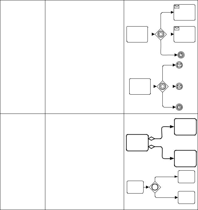
Table 7.2 – BPMN Extended Modeling Elements
Event-Based |
This Decision represents a branching point |
|
|
|
||||
|
where Alternatives are based on an Event |
|
|
|
||||
|
|
|
|
|||||
|
that occurs at that point in the Process (see |
|
|
|
||||
|
page 296) or Choreography (see page 349). |
|
|
|
||||
|
The specific Event, usually the receipt of a |
|
|
|
||||
|
Message, determines which of the paths will |
|
|
|
||||
|
|
|
|
|||||
|
be taken. Other types of Events can be used, |
|
|
|
||||
|
|
|
|
|||||
|
such as Timer. Only one of the Alternatives |
|
|
|
|
|
|
|
|
|
|
|
|
|
|||
|
will be chosen. |
|
|
|
||||
|
There are two options for receiving |
|
|
|
||||
|
Messages: |
|
|
|
||||
|
• Tasks of Type Receive can be used (see |
|
|
|
||||
|
figure top-right). |
|
|
|
||||
|
|
|
|
|||||
|
• Intermediate Events of Type Message can |
|
|
|
||||
|
be used (see figure bottom-right). |
|
|
|
||||
Inclusive |
This Decision represents a branching point |
|
|
|
|
|
|
|
|
|
|
||
|
|
|
|
|
||
|
where Alternatives are based on conditional |
Condition 1 |
|
|||
|
Expressions contained within the |
|
|
|
|
|
|
outgoing Sequence Flows (see page 291). |
|
|
|
|
|
|
In some sense it is a grouping of related |
|
|
|
|
|
|
independent Binary (Yes/No) Decisions. |
|
|
|
|
|
|
Since each path is independent, all |
|
|
|
|
|
|
combinations of the paths MAY be taken, from |
|
|
|
|
|
|
zero to all. However, it should be designed so |
|
|
|
|
|
|
that at least one path is taken. A Default |
Condition 2 |
|
|||
|
Condition could be used to ensure that at |
|
||||
|
least one path is taken. |
|
|
|
|
|
|
There are two versions of this type of |
|
Condition 1 |
|
||
|
Decision: |
|
|
|
|
|
•The first uses a collection of conditional Sequence Flows, marked with minidiamonds (see top-right figure).
• The second uses an Inclusive Gateway |
Condition 2 |
|
|
(see bottom-right picture). |
|
Business Process Model and Notation (BPMN), v2.0.2 |
35 |
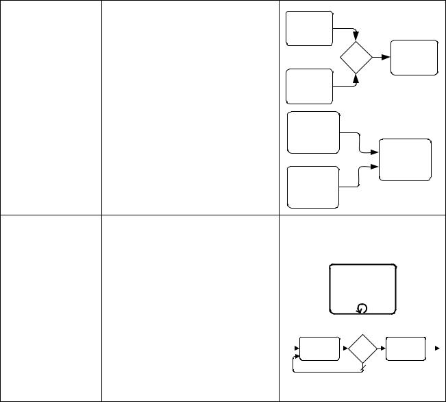
Table 7.2 – BPMN Extended Modeling Elements
Merging |
BPMN uses the term “merge” to refer to the |
|
exclusive combining of two or more paths into |
|
one path (also known as an OR-Join). |
|
A Merging Exclusive Gateway is used to show |
|
the merging of multiple Sequence Flows (see |
|
upper figure to the right). |
|
If all the incoming flow is alternative, then a |
|
Gateway is not needed. That is, uncontrolled |
|
flow provides the same behavior (see lower |
|
figure to the right). |
Looping |
BPMN provides two mechanisms for looping |
||||||
|
within a Process. |
||||||
|
See Next Two Figures |
||||||
|
|
|
|
|
|
|
|
Activity Looping |
The attributes of Tasks and Sub-Processes |
||||||
|
will determine if they are repeated or |
||||||
|
performed once (see page 188). There are |
||||||
|
two types of loops: Standard and Multi- |
||||||
|
Instance. A small looping indicator will be |
||||||
|
displayed at the bottom-center of the activity. |
||||||
|
|
|
|
|
|
|
|
Sequence Flow Looping |
Loops can be created by connecting a |
||||||
|
Sequence Flow to an “upstream” object. An |
||||||
|
object is considered to be upstream if that |
|
|
|
|
|
|
|
object has an outgoing Sequence Flow that |
||||||
|
leads to a series of other Sequence Flows, |
||||||
|
the last of which is an incoming Sequence |
||||||
|
Flow for the original object. |
||||||
36 |
Business Process Model and Notation (BPMN), v2.0.2 |

Table 7.2 – BPMN Extended Modeling Elements
Multiple Instances |
The attributes of Tasks and Sub-Processes |
Sequential |
|
will determine if they are repeated or |
|
|
performed once (see page 190). A set of three |
|
|
horizontal lines will be displayed at the |
|
|
bottom-center of the activity for sequential |
|
|
Multi-Instances (see upper figure to the right). |
|
|
A set of three vertical lines will be displayed at |
|
|
the bottom-center of the activity for sequential |
|
|
Multi-Instances (see lower figure to the right). |
Parallel |
|
|
Process Break |
A Process Break is a location in the Process |
|
|
|
|
|
|
|
(something out of the |
that shows where an expected delay will |
Announce |
|
|
|
|
|
Increment |
|
|
|
||||||
control of the process |
occur within a Process. An Intermediate Event |
Issues for Vote |
|
|
|
|
|
Tally |
|
|
|||||||
|
|
|
||||||
makes the process |
is used to show the actual behavior (see top- |
|
|
Voting |
||||
pause) |
right figure). In addition, a Process Break |
|
Response |
|||||
|
Artifact, as designed by a modeler or |
|
|
|
|
|
|
|
|
modeling tool, can be associated with the |
|
|
|
|
|
|
|
|
Event to highlight the location of the delay |
|
|
|
|
|
|
|
|
within the flow. |
|
|
|
|
|
|
|
|
|
|
|
|
|
|
|
|
Transaction |
A transaction is a Sub-Process that is |
|
|
|
|
|
|
|
|
supported by a special protocol that insures |
|
|
|
|
|
|
|
|
that all parties involved have complete |
|
|
|
|
|
|
|
|
agreement that the activity should be |
|
|
|
|
|
|
|
|
completed or canceled (see page 176). The |
|
|
|
|
|
|
|
|
attributes of the activity will determine if the |
|
|
|
|
|
|
|
|
activity is a transaction. A double-lined |
|
|
|
|
|
|
|
|
boundary indicates that the Sub-Process is a |
|
|
|
|
|
|
|
|
Transaction. |
|
|
|
|
|
|
|
Business Process Model and Notation (BPMN), v2.0.2 |
37 |

Table 7.2 – BPMN Extended Modeling Elements
Nested/Embedded Sub- A nested (or embedded) Sub-Process is an |
|
||
Process (Inline Block) |
activity that shares the same set of data as its |
There is no special indicator for nested Sub- |
|
|
parent process (see page 171). This is |
||
|
Processes |
||
|
opposed to a Sub-Process that is |
||
|
|
||
|
independent, re-usable, and referenced from |
|
|
|
the parent process. Data needs to be passed |
|
|
|
to the referenced Sub-Process, but not to the |
|
|
|
nested Sub-Process. |
|
|
Group (a box around a |
A Group is a grouping of graphical |
|
|
group of objects within |
elements that are within the same Category |
|
|
the same category) |
(see page 66). This type of grouping does not |
|
|
|
affect the Sequence Flows within the Group. |
|
|
|
The Category name appears on the diagram |
|
|
|
as the group label. Categories can be used for |
|
|
|
documentation or analysis purposes. Groups |
|
|
|
are one way in which Categories of objects |
|
|
|
can be visually displayed on the diagram. |
|
|
Off-Page Connector |
Generally used for printing, this object will |
|
|
|
show where a Sequence Flow leaves one |
|
|
|
page and then restarts on the next page. A |
|
|
|
Link Intermediate Event can be used as an |
|
|
|
Off-Page Connector. |
|
|
Association |
An Association is used to link information and |
|
|
|
Artifacts with BPMN graphical elements (see |
|
|
|
page 65). Text Annotations (see page 69) and |
|
|
|
other Artifacts (see page 64) can be |
|
|
|
Associated with the graphical elements. An |
|
|
|
arrowhead on the Association indicates a |
|
|
|
direction of flow (e.g., data), when |
|
|
|
appropriate. |
|
|
Text Annotation |
Text Annotations are a mechanism for a |
|
|
(attached with an |
modeler to provide additional text information |
Descriptive Text |
|
Association) |
for the reader of a BPMN Diagram (see page |
||
Here |
|||
|
69). |
||
Pool
A Pool is the graphical representation of a Participant in a Collaboration (see page 110). It also acts as a “swimlane” and a graphical container for partitioning a set of Activities from other Pools, usually in the context of B2B situations. A Pool MAY have internal details, in the form of the Process that will be executed. Or a Pool MAY have no internal details, i.e., it can be a “black box.”
Name
38 |
Business Process Model and Notation (BPMN), v2.0.2 |