

- •1 Scope
- •1.1 General
- •2 Conformance
- •2.1 General
- •2.2 Process Modeling Conformance
- •2.2.1 BPMN Process Types
- •2.2.2 BPMN Process Elements
- •Descriptive Conformance Sub-Class
- •Analytic Conformance Sub-Class
- •Common Executable Conformance Sub-Class
- •2.2.3 Visual Appearance
- •2.2.4 Structural Conformance
- •2.2.5 Process Semantics
- •2.2.6 Attributes and Model Associations
- •2.2.7 Extended and Optional Elements
- •2.2.8 Visual Interchange
- •2.3 Process Execution Conformance
- •2.3.1 Execution Semantics
- •2.3.2 Import of Process Diagrams
- •2.4 BPEL Process Execution Conformance
- •2.5 Choreography Modeling Conformance
- •2.5.1 BPMN Choreography Types
- •2.5.2 BPMN Choreography Elements
- •2.5.3 Visual Appearance
- •2.5.4 Choreography Semantics
- •2.5.5 Visual Interchange
- •2.6 Summary of BPMN Conformance Types
- •3 Normative References
- •3.1 General
- •3.2 Normative
- •3.3 Non-Normative
- •Activity Service
- •BPEL4People
- •Business Process Definition Metamodel
- •Business Process Modeling
- •Business Transaction Protocol
- •Dublin Core Meta Data
- •ebXML BPSS
- •Open Nested Transactions
- •SOAP 1.2
- •UDDI
- •WfMC Glossary
- •Web Services Transaction
- •Workflow Patterns
- •WSBPEL
- •WS-Coordination
- •WSDL
- •WS-HumanTask
- •XML 1.0 (Second Edition)
- •XML-Namespaces
- •XML-Schema
- •XPath
- •XPDL
- •4 Terms and Definitions
- •5 Symbols
- •6 Additional Information
- •6.1 Conventions
- •6.1.1 Typographical and Linguistic Conventions and Style
- •6.1.2 Abbreviations
- •6.2 Structure of this Document
- •6.3 Acknowledgments
- •Submitting Organizations
- •Supporting Organizations
- •Special Acknowledgments
- •7 Overview
- •7.1 General
- •7.2 BPMN Scope
- •7.2.1 Uses of BPMN
- •Private (Internal) Business Processes
- •Public Processes
- •Collaborations
- •Choreographies
- •Conversations
- •Diagram Point of View
- •Understanding the Behavior of Diagrams
- •7.3 BPMN Elements
- •7.3.1 Basic BPMN Modeling Elements
- •7.3.2 Extended BPMN Modeling Elements
- •7.4 BPMN Diagram Types
- •7.5 Use of Text, Color, Size, and Lines in a Diagram
- •7.6 Flow Object Connection Rules
- •7.6.1 Sequence Flow Connections Rules
- •7.6.2 Message Flow Connection Rules
- •7.7 BPMN Extensibility
- •7.8 BPMN Example
- •8 BPMN Core Structure
- •8.1 General
- •8.2 Infrastructure
- •8.2.1 Definitions
- •8.2.2 Import
- •8.2.3 Infrastructure Package XML Schemas
- •8.3 Foundation
- •8.3.1 Base Element
- •8.3.2 Documentation
- •8.3.3 Extensibility
- •Extension
- •ExtensionDefinition
- •ExtensionAttributeDefinition
- •ExtensionAttributeValue
- •Extensibility XML Schemas
- •XML Example
- •8.3.4 External Relationships
- •8.3.5 Root Element
- •8.3.6 Foundation Package XML Schemas
- •8.4 Common Elements
- •8.4.1 Artifacts
- •Common Artifact Definitions
- •Artifact Sequence Flow Connections
- •Artifact Message Flow Connections
- •Association
- •Group
- •Category
- •Text Annotation
- •XML Schema for Artifacts
- •8.4.2 Correlation
- •CorrelationKey
- •Key-based Correlation
- •Context-based Correlation
- •XML Schema for Correlation
- •8.4.3 Error
- •8.4.4 Escalation
- •8.4.5 Events
- •8.4.6 Expressions
- •Expression
- •Formal Expression
- •8.4.7 Flow Element
- •8.4.8 Flow Elements Container
- •8.4.9 Gateways
- •8.4.10 Item Definition
- •8.4.11 Message
- •8.4.12 Resources
- •8.4.13 Sequence Flow
- •Flow Node
- •8.4.14 Common Package XML Schemas
- •8.5 Services
- •8.5.1 Interface
- •8.5.2 EndPoint
- •8.5.3 Operation
- •8.5.4 Service Package XML Schemas
- •9 Collaboration
- •9.1 General
- •9.2 Basic Collaboration Concepts
- •9.2.1 Use of BPMN Common Elements
- •9.3 Pool and Participant
- •9.3.1 Participants
- •PartnerEntity
- •PartnerRole
- •Participant Multiplicity
- •ParticipantAssociation
- •9.3.2 Lanes
- •9.4 Message Flow
- •9.4.1 Interaction Node
- •9.4.2 Message Flow Associations
- •9.5 Conversations
- •9.5.1 Conversation Node
- •9.5.2 Conversation
- •9.5.3 Sub-Conversation
- •9.5.4 Call Conversation
- •9.5.5 Global Conversation
- •9.5.6 Conversation Link
- •9.5.7 Conversation Association
- •9.5.8 Correlations
- •9.6 Process within Collaboration
- •9.7 Choreography within Collaboration
- •9.8 Collaboration Package XML Schemas
- •10 Process
- •10.1 General
- •10.2 Basic Process Concepts
- •10.2.1 Types of BPMN Processes
- •10.2.2 Use of BPMN Common Elements
- •10.3 Activities
- •Sequence Flow Connections
- •Message Flow Connections
- •10.3.1 Resource Assignment
- •Resource Role
- •Expression Assignment
- •Parameterized Resource Assignment
- •10.3.2 Performer
- •10.3.3 Tasks
- •Service Task
- •Send Task
- •Receive Task
- •User Task
- •Manual Task
- •Business Rule
- •Script Task
- •10.3.4 Human Interactions
- •Notation
- •Manual Task
- •User Task
- •Rendering of User Tasks
- •Human Performers
- •Potential Owners
- •XML Schema for Human Interactions
- •Examples
- •10.3.5 Sub-Processes
- •Embedded Sub-Process (Sub-Process)
- •Reusable Sub-Process (Call Activity)
- •Event Sub-Process
- •Transaction
- •Ad-Hoc Sub-Process
- •10.3.6 Call Activity
- •Callable Element
- •10.3.7 Global Task
- •Types of Global Task
- •10.3.8 Loop Characteristics
- •Standard Loop Characteristics
- •Multi-Instance Characteristics
- •Complex Behavior Definition
- •10.3.9 XML Schema for Activities
- •10.4 Items and Data
- •10.4.1 Data Modeling
- •Item-Aware Elements
- •Data Objects
- •DataObject
- •States
- •Data Objects representing a Collection of Data
- •Visual representations of Data Objects
- •Lifecycle and Accessibility
- •Data Stores
- •Properties
- •Lifecycle and Accessibility
- •Data Inputs and Outputs
- •Data Input
- •States
- •Data Output
- •States
- •Service Task Mapping
- •Send Task Mapping
- •Receive Task Mapping
- •User Task Mapping
- •Call Activity Mapping
- •Script Task Mapping
- •Events
- •InputSet
- •OutputSet
- •Data Associations
- •DataAssociation
- •Assignment
- •DataInputAssociation
- •DataOutputAssociation
- •Data Objects associated with a Sequence Flow
- •10.4.2 Execution Semantics for Data
- •Execution Semantics for DataAssociation
- •10.4.3 Usage of Data in XPath Expressions
- •Access to BPMN Data Objects
- •Access to BPMN Data Input and Data Output
- •Access to BPMN Properties
- •For BPMN Instance Attributes
- •10.4.4 XML Schema for Data
- •10.5 Events
- •10.5.1 Concepts
- •Data Modeling and Events
- •Common Event attributes
- •Common Catch Event attributes
- •Common Throw Event Attributes
- •Implicit Throw Event
- •10.5.2 Start Event
- •Start Event Triggers
- •Start Events for Top-level Processes
- •Start Events for Sub-Processes
- •Start Events for Event Sub-Processes
- •Attributes for Start Events
- •Sequence Flow Connections
- •Message Flow Connections
- •10.5.3 End Event
- •End Event Results
- •Sequence Flow Connections
- •Message Flow Connections
- •10.5.4 Intermediate Event
- •Intermediate Event Triggers
- •Intermediate Events in Normal Flow
- •Intermediate Events Attached to an Activity Boundary
- •Attributes for Boundary Events
- •Activity Boundary Connections
- •Sequence Flow Connections
- •Message Flow Connections
- •10.5.5 Event Definitions
- •Event Definition Metamodel
- •Cancel Event
- •Compensation Event
- •Conditional Event
- •Error Event
- •Escalation Event Definition
- •Link Event Definition
- •Message Event Definition
- •Multiple Event
- •None Event
- •Parallel Multiple Event
- •Signal Event
- •Terminate Event
- •Timer Event
- •10.5.6 Handling Events
- •Handling Start Events
- •Handling Events within normal Sequence Flow (Intermediate Events)
- •Handling Events attached to an Activity (Intermediate boundary Events and Event Sub-Processes)
- •Interrupting Event Handlers (Error, Escalation, Message, Signal, Timer, Conditional, Multiple, and Parallel Multiple)
- •Non-interrupting Event Handlers (Escalation, Message, Signal, Timer, Conditional, Multiple, and Parallel Multiple)
- •Handling End Events
- •10.5.7 Scopes
- •10.5.8 Events Package XML Schemas
- •10.6 Gateways
- •10.6.1 Sequence Flow Considerations
- •10.6.2 Exclusive Gateway
- •10.6.3 Inclusive Gateway
- •10.6.4 Parallel Gateway
- •10.6.5 Complex Gateway
- •10.6.6 Event-Based Gateway
- •10.6.7 Gateway Package XML Schemas
- •10.7 Compensation
- •10.7.1 Compensation Handler
- •10.7.2 Compensation Triggering
- •10.7.3 Relationship between Error Handling and Compensation
- •10.8 Lanes
- •10.9 Process Instances, Unmodeled Activities, and Public Processes
- •10.10 Auditing
- •10.11 Monitoring
- •10.12 Process Package XML Schemas
- •11 Choreography
- •11.1 General
- •11.2 Basic Choreography Concepts
- •11.3 Data
- •11.4 Use of BPMN Common Elements
- •11.4.1 Sequence Flow
- •11.4.2 Artifacts
- •11.5 Choreography Activities
- •11.5.1 Choreography Task
- •11.5.2 Sub-Choreography
- •The Parent Sub-Choreography (Expanded)
- •11.5.3 Call Choreography
- •11.5.4 Global Choreography Task
- •11.5.5 Looping Activities
- •11.5.6 The Sequencing of Activities
- •11.6 Events
- •11.6.1 Start Events
- •11.6.2 Intermediate Events
- •11.6.3 End Events
- •11.7 Gateways
- •11.7.1 Exclusive Gateway
- •11.7.2 Event-Based Gateway
- •11.7.3 Inclusive Gateway
- •11.7.4 Parallel Gateway
- •11.7.5 Complex Gateway
- •11.7.6 Chaining Gateways
- •11.8 Choreography within Collaboration
- •11.8.1 Participants
- •11.8.2 Swimlanes
- •Choreography Task in Combined View
- •Sub-Choreography in Combined View
- •11.9 XML Schema for Choreography
- •12 BPMN Notation and Diagrams
- •12.1 BPMN Diagram Interchange (BPMN DI)
- •12.1.1 Scope
- •12.1.2 Diagram Definition and Interchange
- •12.1.3 How to Read this Clause
- •12.2 BPMN Diagram Interchange (DI) Meta-model
- •12.2.1 Overview
- •12.2.2 Abstract Syntax
- •12.2.3 Classifier Descriptions
- •12.2.4 Complete BPMN DI XML Schema
- •12.3 Notational Depiction Library and Abstract Element Resolutions
- •12.3.1 Labels
- •12.3.2 BPMNShape
- •Markers for Activities
- •Tasks [BPMNShape]
- •Collapsed Sub-Processes [BPMNShape]
- •Expanded Sub-Processes [BPMNShape]
- •Collapsed Ad Hoc Sub-Processes [BPMNShape]
- •Expanded Ad Hoc Sub-Processes [BPMNShape]
- •Collapsed Transactions [BPMNShape]
- •Expanded Transactions [BPMNShape]
- •Collapsed Event Sub-Processes [BPMNShape]
- •Expanded Event Sub-Processes [BPMNShape]
- •Call Activities (Calling a Global Task) [BPMNShape]
- •Collapsed Call Activities (Calling a Process) [BPMNShape]
- •Expanded Call Activities (Calling a Process) [BPMNShape]
- •Data [BPMNShape]
- •Events [BPMNShape]
- •Gateways [BPMNShape]
- •Artifacts [BPMNShape]
- •Lanes [BPMNShape]
- •Pools [BPMNShape]
- •Choreography Tasks [BPMNShape]
- •Collapsed Sub-Choreographies [BPMNShape]
- •Expanded Sub-Choreographies [BPMNShape]
- •Call Choreographies (Calling a Global Choreography Task) [BPMNShape]
- •Collapsed Call Choreographies (Calling a Choreography) [BPMNShape]
- •Expanded Call Choreographies (Calling a Choreography) [BPMNShape]
- •Choreography Participant Bands [BPMNShape]
- •Conversations [BPMNShape]
- •12.3.3 BPMNEdge
- •Connecting Objects [BPMNEdge]
- •12.4 Example(s)
- •12.4.1 Depicting Content in a Sub-Process
- •Expanded Sub-Process
- •Expanded Sub-Process with Start and End Events on Border
- •Collapsed Sub-Process
- •12.4.2 Multiple Lanes and Nested Lanes
- •12.4.3 Vertical Collaboration
- •12.4.4 Conversation
- •12.4.5 Choreography
- •13 BPMN Execution Semantics
- •13.1 General
- •13.2 Process Instantiation and Termination
- •13.3 Activities
- •13.3.1 Sequence Flow Considerations
- •13.3.2 Activity
- •13.3.3 Task
- •13.3.4 Sub-Process/Call Activity
- •13.3.5 Ad-Hoc Sub-Process
- •Operational semantics
- •13.3.6 Loop Activity
- •13.3.7 Multiple Instances Activity
- •13.4 Gateways
- •13.4.1 Parallel Gateway (Fork and Join)
- •13.4.2 Exclusive Gateway (Exclusive Decision (data-based) and Exclusive Merge)
- •13.4.3 Inclusive Gateway (Inclusive Decision and Inclusive Merge)
- •13.4.4 Event-based Gateway (Exclusive Decision (event-based))
- •13.4.5 Complex Gateway (related to Complex Condition and Complex Merge)
- •13.5 Events
- •13.5.1 Start Events
- •13.5.2 Intermediate Events
- •13.5.3 Intermediate Boundary Events
- •13.5.4 Event Sub-Processes
- •Operational semantics
- •13.5.5 Compensation
- •Compensation Handler
- •Compensation Triggering
- •Relationship between Error Handling and Compensation
- •Operational Semantics
- •13.5.6 End Events
- •Process level end events
- •Sub-process level end events
- •14 Mapping BPMN Models to WS-BPEL
- •14.1 General
- •14.2 Basic BPMN-BPEL Mapping
- •14.2.1 Process
- •14.2.2 Activities
- •Common Activity Mappings
- •Task Mappings
- •Service Task
- •Receive Task
- •Send Task
- •Abstract Task
- •Service Package
- •Message
- •Interface and Operation
- •Conversations and Correlation
- •Sub-Process Mappings
- •Mapping of Event Sub-Processes
- •Activity Loop Mapping
- •Standard Loops
- •Dealing with LoopMaximum
- •Multi-Instance Activities
- •14.2.3 Events
- •Start Event Mappings
- •Message Start Events
- •Error Start Events
- •Compensation Start Events
- •Intermediate Event Mappings (Non-boundary)
- •Message Intermediate Events (Non-boundary)
- •Timer Intermediate Events (Non-boundary)
- •Compensation Intermediate Events (Non-boundary)
- •End Event Mappings
- •None End Events
- •Message End Events
- •Error End Events
- •Compensation End Events
- •Terminate End Events
- •Boundary Intermediate Events
- •Message Boundary Events
- •Error Boundary Events
- •Compensation Boundary Events
- •Multiple Boundary Events, and Boundary Events with Loops
- •14.2.4 Gateways and Sequence Flows
- •Exclusive (Data-based) Decision Pattern
- •Exclusive (Event-based) Decision Pattern
- •Inclusive Decision Pattern
- •Parallel Pattern
- •Sequence Pattern
- •Structured Loop Patterns
- •Handling Loops in Sequence Flows
- •14.2.5 Handling Data
- •Data Objects
- •Properties
- •Input and Output Sets
- •Data Associations
- •Expressions
- •Assignments
- •14.3 Extended BPMN-BPEL Mapping
- •14.3.1 End Events
- •14.3.2 Loop/Switch Combinations From a Gateway
- •14.3.3 Interleaved Loops
- •14.3.4 Infinite Loops
- •14.3.5 BPMN Elements that Span Multiple WSBPEL Sub-Elements
- •15 Exchange Formats
- •15.1 Interchanging Incomplete Models
- •15.2 Machine Readable Files
- •15.3.1 Document Structure
- •15.3.2 References within the BPMN XSD
- •15.5 XSLT Transformation between XSD and XMI
- •B.1 Scope
- •B.2 Architecture
- •B.3 Diagram Common
- •B.3.1 Overview
- •B.3.2 Abstract Syntax
- •B.3.3 Classifier Descriptions
- •B.4 Diagram Interchange
- •B.4.1 Overview
- •B.4.2 Abstract Syntax
- •B.4.3 Classifier Descriptions
12.1.3 How to Read this Clause
The normative BPMN 2.0 Diagram Interchange (BPMN DI) specification has three parts. Sub clause 12.2 defines BPMN DI; an instance of the DI meta-model provided at Annex B. Sub clause 12.3 provides a library of the BPMN element depictions and an unambiguous resolution between a referenced BPMN model element and its depiction. Finally, sub clause 12.4 provides examples to support the interpretation of the specification. Some BPMN diagram depictions along with their XML BPMN DI serializations are provided.
12.2 BPMN Diagram Interchange (DI) Meta-model
12.2.1 Overview
The BPMN DI is an instance of the DI meta-model provided at Annex B. The basic concept of BPMN DI, as with DI in general, is that serializing a diagram [BPMNDiagram] for interchange requires the specification of a collection of shapes [BPMNShape] and edges [BPMNEdge] on a plane [BPMNPlane].
BPMNPlane, BPMNShape, and BPMNEdge MUST reference exactly one abstract syntax BPMN element from the BPMN model using the bpmnElement attribute. The only exception is for a Data Association connected to a Sequence Flow (See Figure 10.68). This is a visual short cut that actually normalizes two Data Associations within the BPMN model. In this case, the resolution is made from the BPMN DI attributes rather than the abstract syntax reference [bpmnElement] (See Table 12.35).
The BPMN DI classes only define the visual properties used for depiction. All other properties that are REQUIRED for the unambiguous depiction of the BPMN element are derived from the referenced bpmnElement.
Multiple depictions of a specific BPMN element in a single diagram is NOT allowed, except for Participants in a choreography (i.e., Participant Bands). For example, it is not allowed to depict a Task twice in the same diagram, but it is allowed to depict the same Task in two different diagrams.
BPMN diagrams may be an incomplete or partial depiction of the content of the BPMN model. Some BPMN elements from a BPMN model may not be present in any of the diagram instances being interchanged.
BPMN DI does not provide for any containment concept. The BPMNPlane is an ordered collection of mixed BPMNShape(s) and BPMNEdge(s). The order of the BPMNShape(s) and BPMNEdge(s) inside a BPMNPlane determines their Z-order (i.e., what is in front of what). BPMNShape(s) and BPMNEdge(s) that are meant to be depicted “on top” of other BPMNShape(s) and BPMNEdge(s) MUST appear after them in the BPMNPlane. Therefore, the exporting tool MUST order all BPMNShape(s) and BPMNEdge(s) such that the desired depiction can be rendered.
12.2.2 Abstract Syntax
This sub clause introduces the Abstract Syntax of BPMN DI. BPMN DI is an instance of the DI meta-model provided at Annex B.
368 |
Business Process Model and Notation (BPMN), v2.0.2 |
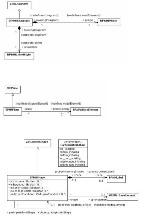
Figure 12.1 – BPMN Diagram
Figure 12.2 – BPMN Plane
Figure 12.3 – BPMN Shape
Business Process Model and Notation (BPMN), v2.0.2 |
369 |

Figure 12.4 – BPMN Edge
Figure 12.5 – BPMN Label
12.2.3 Classifier Descriptions
12.2.3.1 BPMNDiagram [Class]
BPMNDiagram is a kind of diagram that depicts all or part of a BPMN model.
Description
BPMNDiagram represents a depiction of all or part of a BPMN model. It specializes DI::Diagram and redefines the root element (the top most diagram element) to be of type BPMNPlane. A BPMN diagram can also own a collection of BPMNStyle elements that are referenced by BPMNLabel elements in the diagram. These style elements represent the unique appearance styles used in the diagram.
Abstract Syntax
• Figure 12.1 - BPMN Diagram
370 |
Business Process Model and Notation (BPMN), v2.0.2 |
Generalizations
• DI::Diagram
Associations
• + plane : BPMNPlane [1] {redefines rootElement}
a BPMN plane element that is the container of all diagram elements in this diagram.
• + labelStyle : BPMNLabelStyle [*] {subsets style}
a collection of BPMN label styles that are owned by the diagram and referenced by label elements.
Table 12.1 – BPMNDiagram XML schema
<xsd:complexType name="BPMNDiagram"> <xsd:complexContent>
<xsd:extension base="di:Diagram"> <xsd:sequence>
<xsd:element ref="bpmndi:BPMNPlane"/>
<xsd:element ref="bpmndi:BPMNLabelStyle" minOccurs="0" maxOccurs="unbounded"/> </xsd:sequence>
</xsd:extension>
</xsd:complexContent>
</xsd:complexType>
12.2.3.2 BPMNPlane [Class]
A BPMNPlane is the BPMNDiagram container of BPMNShape and BPMNEdge.
Description
A BPMNPlane specializes DI::Plane and redefines its model element reference to be of type (BPMN) BaseElement. A BPMNPlane can only reference a BaseElement of the types: Process, SubProcess, AdHocSubProcess, Transaction, Collaboration, Choreography or SubChoreography.
BPMNPlane element is always owned by a BPMNDiagram and represents the root diagram element of that diagram. The plane represents a 2 dimensional surface with an origin at (0, 0) along the x and y axes with increasing coordinates to the right and bottom. Only positive coordinates are allowed for diagram elements that are nested in a BPMNPlane. This means that the union of all the nested elements’ bounds is deemed to be located at the plane’s origin point.
Abstract Syntax
•Figure 12.1 - BPMN Diagram
•Figure 12.2 - BPMN Plane
Generalizations
• DI::Plane
Business Process Model and Notation (BPMN), v2.0.2 |
371 |
Associations
• + bpmnElement : BaseElement [0..1] {redefines modelElement}
a reference to either a Process, SubProcess, AdHocSubProcess, Transaction, Collaboration, Choreography or SubChoreography in a BPMN model.
Table 12.2 – BPMNPlane XML schema
<xsd:complexType name="BPMNPlane"> <xsd:complexContent>
<xsd:extension base="di:Plane">
<xsd:attribute name="bpmnElement" type="xsd:QName"/> </xsd:extension>
</xsd:complexContent>
</xsd:complexType>
12.2.3.3 BPMNShape [Class]
BPMNShape is a kind of shape that can depict a BPMN model element.
Description
BPMNShape represents a depiction of a (typically a node) BPMN model element. It specializes DI::LabeledShape and redefines its model element reference to be of type (BPMN) BaseElement, allowing it to reference an element from a BPMN model.
BPMNShape also contains an optional label of type BPMNLabel that can be nested in the shape when it has a visible textual label with its own bounding box.
The shape also contains a number of normative notational options that can be specified for different types of BPMN elements depicted by the shape. Those options, each represented by a separate property, and described below, allow for recording the specific notational style desired for the shape.
All BPMNShape elements are owned directly by a BPMNPlane (that is the root element in a BPMNDiagram), i.e., shapes are not nested within each other in the BPMN DI model although they may appear that way when depicted. The bounds of a BPMNShape are always relative to that plane’s origin point and are REQUIRED to be positive coordinates. Note that the bounds’ x and y coordinates are the position of the upper left corner of the shape (relative to the upper left corner of the plane).
Abstract Syntax
•Figure 12.3 - BPMN Shape
•Figure 12.4 - BPMN Edge
Generalizations
• DI::LabeledShape
372 |
Business Process Model and Notation (BPMN), v2.0.2 |
Attributes
• + isHorizontal : Boolean [0..1]
an optional attribute that should be used only for Pools and Lanes. It determines if it should be depicted horizontally (true) or vertically (false).
• + isExpanded : Boolean [0..1]
an optional attribute that should be used only for SubProcess, AdHocSubProcess, Transaction, SubChoreographies, CallActivities, and CallChoreographies. It determines if it should be depicted expanded (true) or collapsed (false).
•+ isMarkerVisible : Boolean [0..1]
an optional attribute that should be used only for Exclusive Gateway. It determines if the marker should be depicted on the shape (true) or not (false).
• + participantBandKind : ParticipantBandKind [0..1]
an optional attribute that should only be used for Participant Bands. If this attribute is present, it means that the participant should be depicted as a Participant Band instead of as a Pool.
• + isMessageVisible : Boolean [0..1]
an optional attribute that should only be used for Participant Bands. It determines if an envelope decorator should be depicted linked to the Participant Band.
• + choreographyActivityShape : BPMNShape [0..1]
an optional attribute that should only be used for Participant Bands. It is REQUIRED for a BPMNShape depicting a Participant Band. This is REQUIRED in order to relate the Participant Band to the BPMNShape depicting the Choreography Activity that this Participant Band is related to.
Associations
• + bpmnElement : BaseElement [0..1] {redefines modelElement}
a reference to a BPMN node element that this shape depicts. Note that although optional a bpmnElement must be provided for a BPMNShape.
• + label : BPMNLabel [0..1] {subsets ownedLabel}
an optional label that is nested when the shape has a visible text label with its own bounding box.
Business Process Model and Notation (BPMN), v2.0.2 |
373 |
Table 12.3 – BPMNShape XML schema
<xsd:complexType name="BPMNShape"> <xsd:complexContent>
<xsd:extension base="di:LabeledShape"> <xsd:sequence>
<xsd:element ref="bpmndi:BPMNLabel" minOccurs="0"/> </xsd:sequence>
<xsd:attribute name="bpmnElement" type="xsd:QName"/> <xsd:attribute name="isHorizontal" type="xsd:boolean"/> <xsd:attribute name="isExpanded" type="xsd:boolean"/> <xsd:attribute name="isMarkerVisible" type="xsd:boolean"/> <xsd:attribute name="isMessageVisible" type="xsd:boolean"/>
<xsd:attribute name="participantBandKind" type="bpmndi:ParticipantBandKind"/> <xsd:attribute name="choreographyActivityShape" type="xsd:QName"/>
</xsd:extension>
</xsd:complexContent>
</xsd:complexType>
12.2.3.4 ParticipantBandKind [Enumeration]
ParticipantBandKind defines the type of Participant Band to depict.
Description
Participant bands can be depicted in 3 ways:
1.a top band is rectangular with rounded corners at the top
2.a middle band is rectangular
3.a bottom band is rectangular with rounded corners at the bottom Participant bands can be depicted in 2 shadings:
1.initiating (the band should not be shaded)
2.non_initiating (the band should be shaded)
Abstract Syntax
• Figure 12.3 - BPMN Shape
Literals
•top_initiating - the band should be depicted as a non shaded top band
•middle_initiating - the band should be depicted as a non shaded middle band
•bottom_initiating - the band should be depicted as a non shaded bottom band
•top_non_initiating - the band should be depicted as a shaded top band
•middle_ non_initiating - the band should be depicted as a shaded middle band
•bottom_ non_initiating - the band should be depicted as a shaded bottom band
374 |
Business Process Model and Notation (BPMN), v2.0.2 |
12.2.3.5 BPMNEdge [Class]
BPMNEdge is a kind of edge that can depict a relationship between two BPMN model elements.
Description
BPMNEdge represents a depiction of a relationship between two (source and target) BPMN model elements. It specializes DI::LabeledEdge and redefines its model element reference to be of type (BPMN) BaseElement, allowing it to reference a relationship element from a BPMN model.
BPMNEdge also redefines its source and target references to be of type DiagramElement (either BPMNShape or BPMNEdge).
The source or target definition should only be present if the edge is depicted between a different source or target than the one referenced by the BPMN model element of the BPMNEdge. Only the different source or target is REQUIRED. Both attributes should be present only if both are different. This is the case, for instance, if a Message Flow target is not depicted in the current diagram because it is inside a black box Pool. The Message Flow could then define its target as being the BPMNShape depicting the Pool to connect it to the boundary of that black box Pool.
BPMNEdge also contains an optional label of type BPMNLabel that can be nested in the edge when it has a visible textual label with its own bounding box.
All BPMNEdge elements are owned directly by a BPMNPlane (that is the root element in a BPMNDiagram). The waypoints of BPMNEdge are always relative to that plane’s origin point and are REQUIRED to be positive coordinates.
Abstract Syntax
• Figure 12.4 - BPMN Edge
Generalizations
• DI::LabeledEdge
Associations
• + label : BPMNLabel [0..1] {subsets ownedLabel}
an optional label that is nested when the edge has a visible text label with its own bounding box.
• + bpmnElement : BaseElement [0..1] {redefines modelElement}
a reference to a connecting BPMN element that this edge depicts. Note that this reference is only optional for the specific case of a Data Association connected to a Sequence Flow; in all other cases a referenced element must be provided.
• + sourceElement : DiagramElement [0..1] {redefines source}
an optional reference to the edge’s source element if it is different from the source inferred from the bpmnElement association.
• + targetElement : DiagramElement [0..1] {redefines target}
an optional reference to the edge’s target element if it is different from the target inferred from the bpmnElement association.
• messageVisibleKind : MessageVisibleKind [0..1]
an optional attribute that should be used only for Message Flow. It determines if an envelope decorator should be depicted and the kind of envelope to be depicted.
Business Process Model and Notation (BPMN), v2.0.2 |
375 |
Table 12.4 – BPMNEdge XML schema
<xsd:complexType name="BPMNEdge"> <xsd:complexContent>
<xsd:extension base="di:LabeledEdge"> <xsd:sequence>
<xsd:element ref="bpmndi:BPMNLabel" minOccurs="0" /> </xsd:sequence>
<xsd:attribute name="bpmnElement" type="xsd:QName" /> <xsd:attribute name="sourceElement" type="xsd:QName" /> <xsd:attribute name="targetElement" type="xsd:QName" />
<xsd:attribute name="messageVisibleKind" type="bpmndi:MessageVisibleKind" /> </xsd:extension>
</xsd:complexContent>
</xsd:complexType>
12.2.3.6 MessageVisibleKind [Enumeration]
MessageVisibleKind defines the type of envelope that is visible.
Description
MessageVisibleKind is applicable only to Participant Band and Message Flow.
For Message Flow, the envelope should be positioned in the middle of the edge.
For Participant Band, the envelope should be positioned over (for top band) or under (for bottom band) and connected to the band using an association. Note that only Choreography Task Participant Bands are allowed to show the envelope. Middle bands being only used for a SubChoreography can thus not have envelope showing.
Abstract Syntax
• Figure 12.3 - BPMN Shape
Literals
•initiating - The envelope should not be shaded.
•non_inititating - The envelope should be shaded.
12.2.3.7 BPMNLabel [Class]
BPMNLabel is a kind of label that depicts textual info about a BPMN element.
Description
BPMNLabel represents a depiction of some textual information about a BPMN element. It specializes DI::Label and redefines its style reference to be of type BPMNLabelStyle, which contains information about the appearance of the label (e.g., the chosen font). The referenced style is owned by the diagram that nests the label.
A BPMN label is not a top-level element but is always nested inside either a BPMNShape or a BPMNEdge. It does not have its own reference to a BPMN element but rather inherits that reference (if any) from its parent shape or edge. The textual info depicted by the label is derived from that referenced BPMN element.
376 |
Business Process Model and Notation (BPMN), v2.0.2 |
The bounds of BPMNLabel are always relative to the containing plane’s origin point. Note that the bounds’ x and y coordinates are the position of the upper left corner of the label (relative to the upper left corner of the plane).
Abstract Syntax
•Figure 12.3 - BPMN Shape
•Figure 12.4 - BPMN Edge
•Figure 12.5 - BPMN Label
Generalizations
• DI::Label
Associations
• + labelStyle : BPMNLabelStyle [0..1] {redefines style}
an optional reference to a label style (owned by the diagram) that gives the appearance options for the label. If not specified, the style of the label can be assumed by a tool.
Table 12.5 – BPMNLabel XML schema
<xsd:complexType name="BPMNLabel"> <xsd:complexContent>
<xsd:extension base="di:Label">
<xsd:attribute name="labelStyle" type="xsd:QName" /> </xsd:extension>
</xsd:complexContent>
</xsd:complexType>
12.2.3.8 BPMNLabelStyle [Class]
BPMNLabelStyle is a kind of style that gives the appearance options for a BPMNLabel.
Description
BPMNLabelStyle represents the appearance options for elements of type BPMNLabel. It specializes DI::Style and contains a description of a font that is used in depicting a BPMNLabel. One or more labels may reference the same BPMNLabelStyle element, which must be owned by a BPMNDiagram.
Abstract Syntax
•Figure 12.1 - BPMN Diagram
•Figure 12.5 - BPMN Label
Generalizations
• DI::Style
Attributes
•+ font : Font[1] - a font object that describes the properties of the font used for depicting the labels that reference this style.
Business Process Model and Notation (BPMN), v2.0.2 |
377 |