

2383
.pdfreduce local bending moments in the edge girders.
The slab was analyzed with due consideration of its nonlinear behavior due to the high compression in the bridge deck. The bridge girder was also designed to provide sufficient capacity for possible accidental failure of a stay cable. Under this emergency condition the deck had to be able to safely carry a reduced live load.
Cables
Two types of cables were considered in the design: parallel wire cables and the seven-wire strand cables. Due to the difference in the stiffness of these two types of cables, the structure was analyzed for both types in order to ascertain that selection of either type would be satisfactory for the structure. The performance requirement of the cables basically conformed to the recommendations of the American PostTensioning Institute. In addition, the strand anchorages were also tested for fatigue loading without grout in order to assure the effectiveness of the cables under the unlikely condition of defective grout in the anchorage.
Construction
Construction of the deck girder was by means of a cable-supported form traveller. The contractor added water ballast to the traveler. This was to allow the stressing of the cables to a higher force before the concrete was cast. The water ballast was released as fresh concrete was poured in a seg-
ment. This increased the weight of the traveller to over 2001.
The contractor elected to use the seven wire strand alternate for the cables. The "Stronghold" system was successfully tested according to the specifications at the University of Munich, Germany. The strands were installed one at a time and first anchored by means of a mono-strand jack. The entire cable was then stressed using a single large multi-strand jack. All jacking was done from the tower end.
The strands were placed inside plastic pipe. The space between the pipe and the strands was grouted with cement grout. The pipes were wrapped with white tape to give extra protection and to reduce the cables' temperature. Besides, the white color enhanced the appearance of the bridge.
As specified in the bid document, the contractor hired a consulting engineer to provide the construction engineering for the bridge. The submission was reviewed in detail by the owner's inhouse engineers and by the designer to assure that the construction met the intent of the design. In addition, the designer was represented at the site to assist the owner in quality control of construction.
Owner: City of Savannah, GA
Design engineers:
DRC Consultants, Inc., Flushing, NY
Construction engineers:
Buckland and Taylor, Vancouver, BC, Canada
Main contractors:
Monterey Inc., San Francisco, CA Groves Inc., Minneapolis, MN
Service Date: 1990.
ACOSTA BRIDGE REPLACEMENT, JACKSONVILLE, FLORIDA
Brett H. Pielstick, Civil Eng. |
of the old crossing which lay between |
|||
Steinman, |
Boynton, |
Gronquist & |
a railroad bridge and the new bridge. |
|
Birdsall, Daytona Beach, FL |
The third and final stage of construc- |
|||
Project Description |
|
tion entailed maintaining traffic on the |
||
|
new eastern bridge and constructing |
|||
The new Acosta Bridge is a USD 148 |
the western bridge. |
|||
Scour Protection |
||||
million project crossing the St. John's |
||||
River in |
downtown |
Jacksonville, |
|
|
Florida. This project features twin five- |
As downtown Jacksonville grew, more |
|||
span structures, each totalling 501 m in |
land was created by filling the St. |
|||
length. |
Cast-in-place |
segmental |
John's River in areas adjacent to the |
|
concrete box girder construction was |
Acosta Bridge. The substantial reduc- |
|||
used throughout with the exception of |
tion in river area created a scour con- |
|||
the approach spans. |
|
dition that removed over 10 m of ma- |
||
The asymmetrical main span of 192 m |
terial from areas around the founda- |
|||
was built by balanced cantilever con- |
tions of the old bridge. Several founda- |
|||
struction with traveling forms. The ap- |
tions of the old bridge had only 0.6 m |
|||
proach spans for the river crossing |
of embedment remaining at the time of |
|||
were constructed span-by-span on |
demolition. After the superstructure of |
|||
falsework. The approaches and corre- |
the old structure was removed, stability |
|||
sponding ramps to the river bridge |
cables were required to keep the old |
|||
were constructed of steel plate and box |
columns from falling over. |
|||
girders. |
|
|
Gabion mats were used to combat the |
|
The project was designed to be con- |
extreme scour conditions around the |
|||
structed in three separate stages in or- |
old Acosta Bridge, the 60 year old rail- |
|||
der to maintain the flow of traffic and |
road bridge, and the new Acosta |
|||
limit the amount of additional right of |
Bridge. These 4.9 m x 11.0 m mats |
|||
way required for the new structure. |
were constructed using PVC-coated, |
|||
Stage one involved the construction of |
chain link fabric mesh mattresses filled |
|||
the eastern three lane bridge, while |
with rock to a thickness of 230 mm. |
|||
traffic was maintained on the old |
The gabion mats were placed in layers |
|||
Acosta Bridge. Stage two involved the |
on the river bottom arid laced together |
|||
placement of traffic on the new eastern |
underwater. Rip-rap and filter fabric |
|||
three lane bridge, allowing demolition |
were placed around piers and drilled |
|||
shafts to provide continuity of the |
MN pot bearings and are among the |
|||
scour protection system. |
|
largest bearings of their type in North |
||
FOUNDATION |
AND |
America. One of each of these large |
||
bearings was tested at the US National |
||||
SUBSTRUCTURE |
|
Testing |
Laboratory |
near Washington, |
|
|
DC. |
|
|
The new Acosta Bridge is supported |
The cantilevers were erected by bal- |
|||
on 1.5 m diameter drilled shafts with 7 |
anced |
cantilever |
construction. The |
|
to 8 shafts per back span support, and |
cantilever was limited to about one- |
|||
31 and 22 shafts for each of the two |
half of a segment out of balance |
|||
main piers making a total of 82 shafts |
through the entire casting process to |
|||
per bridge. An extensive test program |
minimize the unbalanced moments. |
|||
utilizing 900 mm test shafts was used |
A stability system was required to sup- |
|||
to check capacities. Testing involved |
port the out of balance moment. This |
|||
the use of sister bar strain gauges, |
system consisted of three 1.1m |
|||
Osterburg cells, telltales and a wire |
diameter concrete filled steel pipes |
|||
line to measure stresses and |
with 15.9 mm walls. One support was |
|||
movements. The use of the Osterburg |
located under each web of the box. |
|||
hydraulic cell was innovative for this |
Grout pads on the footing provide |
|||
type of equipment, being applied in a |
lower support for this system. These |
|||
silty clay marl to determine end bear- |
pipes served as compression posts on |
|||
ing capacity. |
|
each side of the column 4.9 m from the |
||
|
center of rotation. At the top of each |
|||
Waterline footings were constructed on |
||||
the drilled shafts using a ring support |
post, a sand jack with a concrete |
|||
bolted to each drilled shaft. With the |
wedge was placed to provide the con- |
|||
rings in place, a 230 mm thick precast |
nection under the pier table bottom |
|||
seal slab was set. A top yoke support |
slab. |
|
|
|
system was then used to support the |
Superstructure |
|
||
footing side forms. A 460 mm to 530 |
|
|||
mm seal was then placed, enabling the |
The river crossing is a five-span |
|||
removal of 1 m of water from the |
||||
forms. The footing, column and cap |
continuous structure composed of a 67 |
|||
were then constructed with |
conven- |
m back span, 110 m side span, 192 m |
||
tional cast-in-place methods. |
|
main span, 83.8 m side span and a 48.8 |
||
|
m back span. The superstructure |
|||
Due to physical restraints, and in an ef- |
||||
fort to minimize the size of the founda- |
utilized cast-in-place segmental con- |
|||
tions, the designer used pot bearings to |
struction with a typical box section |
|||
support the bridge at all pier locations. |
measuring 23.10 m wide at the deck |
|||
The larger of the two cantilevers was |
(Fig. 24). The box girder out-to-out |
|||
erected on three 53.4 MN fixed pot |
width of 14.94 m consists of two cells |
|||
bearings. The second antilever bearing |
and three web walls. The depth of the |
|||
system consists of three guided 38.7 |
boxes varies from 3.66 m at mid-span |
|||

to 11.58 m at the main pier table. A typical segment pour was 4.9 m long. The casting cycle was five days per traveller.
Segments were post-tensioned once the concrete reached 24.13 MPa of the 37.92 MPa 28-day requirement. Three tendons made of fifteen 15 mm diameter strands were stressed to about 3.1 kN each after casting each cycle. Fourstrand transverse tendons spaced approximately 760 mm were stressed during the same cycle. Vertical web shear reinforcement was provided by 31.75 mm post-tensioning bars.
To speed up construction, the contractor varied from the designer's erection procedures and built the back spans on falsework. This allowed the cantilever construction to go on independent of the back spans. The resulting time savings exceeded 16 weeks.
of the old Acosta Bridge. Historical levels for service vibrations were recorded by instrumentation placed on the old railroad bridge. Based on the recorded information and current blast literature, a blast limit was set for the railroad bridge at 101 mm/s peak particle velocity.
Throughout the blasting, monitors were
placed on the railroad bridge and the new
Acosta Bridge to measure the particle
velocities. As the blasting progressed, the
blaster was able to use this information to set
off more than 635 kg of explosive powder in
one blast and remain within the peak particle
velocity limits established for the project.
Owner-Florida Department of
Transportation
Construction Engineering and
Inspection:
Steinman Boynton Gronquist and
Birdsall, Tallahassee, FL
Fig. 24
Vibration Limits
One of the greatest concerns in the project was the 60 year old railroad bridge located about 12 m to the west
Contractor:
Recchi America, Miami, FL
Engineers of Record:
DRC Consultants, Flushing, NY
Fred Wilson & Assoc, Jacksonville, FL
Service date: July 1994
THE NORMANDIE BRIDGE, FRANCE:
A NEW RECORD FOR CABLE-STAYED BRIDGES
Michel Virlogeux
Prof., Ecole Nationale des Ponts et Chausees, Paris, France
Landmark Cable-Stayed Bridges
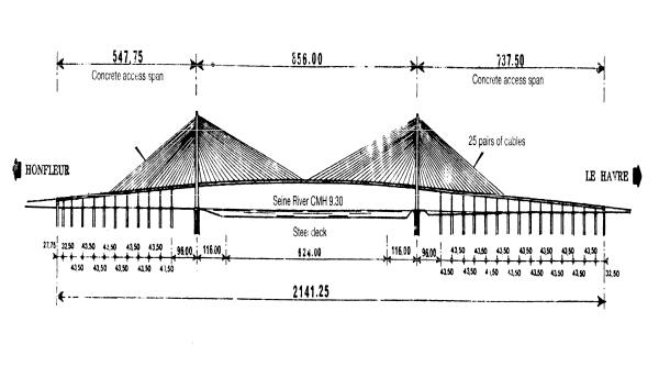
On August 8, 1994, the last steel plate was welded to close the main span of the Normandie Bridge, which, at 856 m, is the longest cable-stayed span in the world today (Fig. 25). The Normandie Bridge will begin its service life in January 1995. This is an appropriate occasion to analyse its design and review the experience gained during the construction thus far.
Anacis Island, Canada) and 490 m in 1991 (Ikuchi Bridge, Japan).
But engineers already had some indications that cable-stayed bridges were very far from their limits: three major bridges had been built in Germany with a single pylon: the Koln Severin Bridge (302 m in 1959), the Diisseldorf Kniebrucke (320 m in 1969) and the Diisseldorf Flehe Bridge (368 m in 1979). For those who could foresee it, these three bridges proved that spans
of 600-700 m could be built from two pylons without major problems.
Fig. 25
In the 1970s and '80s, it was generally |
Some projects had been studied with |
considered that 500 m was a limit for |
long spans, but the bridges had not |
cable-stayed bridges, and almost all |
been erected at the time: a first design |
projects were conceived with such a |
was done for the Normandie Bridge |
limit in mind. Consequently, the record |
between 1976 and 1979, with a main |
span progressed slowly: 404 m in 1975 |
span 510 in long; and a cable-stayed |
(Saint-Nazaire, France), 430 m in 1983 |
solution was proposed in 1978 for the |
(Barrios de Luna Bridge, Spain), 465 |
Eastern Bridge of the Storebaelt, Den- |
m in 1986 (John Frazer Bridge to |
mark, with a span of 780 m. |
Fritz Leonhardt proposed a cable- |
1200 m. All problems found |
||||
stayed solution in 1968-1970 for cross- |
appropriate solutions, illustrating the |
||||
ing the Messina Straits with two |
fantastic possibilities of cable-stayed |
||||
pylons in the sea and a main span 1300 |
bridges, but navigation requirements |
||||
m long. He was followed by Rene |
finally called for a 1624 m long main |
||||
Walther, who proposed that concrete |
span, longer that the longest suspended |
||||
cable-stayed bridges can be economi- |
span in the world, and the cable-stayed |
||||
cally built up to 600 m, and composite |
solution was abandoned. |
||||
ones up to 800 m. |
|
|
It is now interesting to compare the |
||
Recent Progress |
|
|
cable-stayed bridges which held the |
||
|
|
successive world records: |
|||
|
|
|
|
- Saint-Nazaire Bridge, 1975: steel |
|
The preliminary design of the Nor- |
orthotropic box-girder ... |
||||
mandie Bridge - called the Honfleur |
- Barrios de Luna Bridge, 1983: |
||||
Bridge at the time - was developed be- |
prestressed concrete bridge |
||||
tween September, 1986 and Spring, |
- |
Anacis Bridge, 1986: |
|||
1987. The project was presented in the |
composite deck with two I-shaped |
||||
first conference devoted to cable- |
beams and a concrete sfab |
||||
stayed bridges, in Bangkok, in Novem- |
- |
Ikuchi Bridge, 1991: |
|||
ber 1987. |
|
|
|
steel main span (and concrete access |
|
Since that time, the world record pro- |
spans, like the Normandie Bridge) |
||||
gressed with two bridges designed and |
made of two parallel box-girders |
||||
built very quickly, probably helped by |
- |
Skarnsund Bridge, 1991: prestressed |
|||
the Normandie Bridge project, which |
concrete |
||||
psychologically opened the way for |
- Yangpu Bridge, 1993: composite |
||||
very long spans: the Skarnsund Bridge |
construction |
||||
in Norway (530 m in November, |
- Normandie Bridge, 1994: steel |
||||
1991), and the Yangpu Bridge in |
orthotropic box-girder for its main |
||||
Shanghai, China (602 m in October, |
span. |
||||
1993). Two other projects were clearly |
The cycle is closed, and a concrete ca- |
||||
inspired by « the Normandie Bridge: |
ble-stayed bridge with a main span of |
||||
the Honshu Shikoku Bridge Authority |
about 1000 m cannot be expected; nor |
||||
decided, |
after |
the |
Bangkok |
probably a composite one due to high- |
|
Conference, that the Tatara Bridge |
er weight and increasing costs of ca- |
||||
would not be a suspension bridge, but |
bles. But the competition which exist- |
||||
a cable-stayed one. Its erection began |
ed during twenty years between con- |
||||
in 1993, and it will become, in 1998 or |
crete, composite and steel decks is an- |
||||
999, the new world record with its |
other indication that the limits have not |
||||
main span 890 m long. Danish |
have reached. |
||||
engineers designed a new cable-stayed |
|
|
|||
solution for the East Bridge of the Storebaelt, extending the main span to

MAIN ASPECTS OF THE |
to be adapted to both concrete and |
DESIGN |
steel structures, since the deck is in |
|
prestressed concrete in the access |
While the Normandie fridge is likely |
spans (Fig. 26) and in steel in the |
be surpassed by even longer bridges in |
central part of the main span (Fig. 27). |
the years to come - the Tatara Bridge |
|
and still longer ones very soon there- |
|
after - it is of major importance in the |
|
technical evolution of long-span |
|
bridges. It is the first cable-stayed |
|
bridge entering the domain of very |
|
long spans, which was reserved up to |
|
now for suspension bridges. For this |
|
reason, it is worth pointing at the most |
|
important aspects of its design. |
Fig. 26 |
Wind-Governed Design
The design of long span bridges is governed by wind and wind effects. The Normandie Bridge helped or inspired the design of other bridges, and it is also true that the Normandie Bridge itself was very much inspired from the suspension bridges designed by Freeman Fox and Partners: UK's Severn Bridge and Humber Bridge, and Turkey's first Bosphorus Bridge. As Klaus Ostenfeld once remarked when discussing the new cable-stayed solution for the Storebaelt in Denmark, "Engineers are climbing over each other's shoulders."
The main aspects of the wind design of the Normandie Bridge are:
- The streamlined cross section of the deck, to reduce wind forces and to increase the aerodynamic stability of the bridge. The streamlining is clearly inspired from the English bridges mentioned above, but the final shape was selected for specific reason: it had

|
|
|
|
|
|
inverted Y to concentrate the higher |
|
|
|
Fig. 27 |
|
|
anchorages of ables on the bridge |
||
|
|
|
|
longitudinal axis. |
|||
- A high torsional rigidity, to clearly |
|||||||
- The shape of the pylon - an inverted |
|||||||
separate the vibration periods in |
Y - is also extremely efficient at |
||||||
torsion and vertical bending. For this |
resisting transverse wind forces (Fig. |
||||||
reason, the deck is a box girder |
28). |
||||||
suspended on both sides. In addition, |
Fig. 28 |
||||||
the |
pylons have |
the shape of an |
|||||
|
|||||||
- |
The |
concrete |
and |
steel |
composite |
Fig. 29 |
|
deck, with concrete access spans on |
Composite Construction |
||||||
close supports extended at a distance |
The second major point in the design |
||||||
of 116 m from each pylon in the |
of the Normandie Bridge is the combi- |
||||||
central span, as well as the rigid |
nation of prestressed concrete and |
||||||
connection between deck and pylons, |
steel. Composite designs, where con- |
||||||
increases the structure's rigidity. Wind- |
crete and steel are used to their greatest |
||||||
induced |
deflections |
are |
drastically |
efficiency, are strongly endorsed by |
|||
reduced. Alan Davenport compared the |
the designers of the Normandie Bridge. |
||||||
deformability of the Normandie Bridge |
The Normandie Bridge combines con- |
||||||
with the Littlebelt suspension bridge - |
crete and steel for the design of the |
||||||
also efficiently built with a streamlined |
deck, prestressed concrete in the access |
||||||
deck based on the English experience |
spans, on close supports, with an |
||||||
and a main span of only 600 m - and |
extension in the main span on both |
||||||
concluded that the Normandie Bridge |
sides. Only the central part of the m, in |
||||||
behaves like a cable-stayed bridge with |
span is an orthotropic steel box girder, |
||||||
a much shorter main span and is much |
much lighter (9 t/m, instead of the |
||||||
more rigid than a suspension bridge |
usual 45 t/n) to limit the cable size. |
||||||
with a span of 500-600 m. |
|
The use of concrete in the access spans |
|||||
|
|
|
|
|
|
reduces total costs and increases the |
|
|
|
|
|
|
|
bridge's rigidity, as well as the back |
|
|
|
|
|
|
|
staying efficiency of all rear cables. |
|
|
|
|
|
|
|
This efficient combination of concrete |
|
and steel in cable-stayed decks had been used before for the design of the Tampico Bridge in Mexico (360 m, 1988) and of the Ikuchi Bridge in Japan (490 m, 1991). And prior to that, much valuable experience had been gained about using various materials, such as traditional and lightweight concrete, in Dutch bridges built by the cantilever method (Nijmegen bridges, around 1970). The experience gained
in using different weights for a specific |
divided into two half-elements) to be |
structural purpose proved to be ex- |
lifted by the site crane (capacity: 20 t), |
tremely useful (the bridges at |
and welded on site. The typical |
Ottmarsheim and Tricastin and the |
element was designed to anchor a pair |
cable-stayed bridge over the Elorn |
of cables on each side. The main plates |
River). |
were divided in ties for the transfer of |
The Normandie Bridge also uses a |
forces from the main span to back- |
composite design for the upper part of |
stays in order to lighten the elements, |
the pylons, where cables are anchored |
reduce in situ welds and facilitate |
(Fig. 29). It is far more efficient to de- |
access from the lateral cells of the |
sign a steel anchorage box to anchor |
pylon - with a lift - to the anchorages. |
the cables, since steel plates easily car- |
High Performance Concrete |
ry tensile stresses from back-stays to |
|
cables suspending the main span. In |
|
addition, it is much easier to fabricate |
The main advantage of high perfor- |
these steel anchorage boxes - or the |
mance concrete for standard and |
elements which will constitute them - |
medium span bridges is substantially |
in a factory than on site in concrete |
enhanced durability. But for heavily |
100 or 200 m above ground. To |
loaded elements, such as the pylons of |
achieve the proper geometry, it is |
cable-stayed bridges with long spans, |
necessary to precisely adjust the |
or the concrete deck of the Normandie |
position of steel elements ants which |
Bridge, which has to balance high |
are later completed by concrete walls. |
stresses from wind effects, high perfor- |
Probably the first application of this |
mance concrete has great structural |
technique was in Belgium, for the |
advantages. |
construction of the Ben Ahin and |
All concrete on the Normandie Bridge |
Wandre Bridges, designed by Rene |
contains silica fume for a characteristic |
Greisch ond Jean-Marie Cremer. The |
strength of 60 MPa. This allowed for a |
idea was used again for the Evripos |
reduction in the cross section of the |
Bridge in Greece and for the Chalon- |
concrete in the pylons and deck and |
sur-Saone Bridge in France. The |
thus a reduction in weight and founda- |
problem was more complex in the |
tions. |
Normandie Bridge, with the transverse |
Erection of the Access Spans |
inclination of cables. A design was |
|
developed with Jean-Claude Foucriat, |
|
introducing horizontal prestressing |
The erection of access spans on both |
tendons to press the concrete walls |
banks required the contractors to de- |
against the steel anchorage boxes to |
velop a new technology. Classical |
help the transfer of vertical forces from |
erection techniques, with Teflon pads, |
steel to concrete. |
would have produced very significant |
The steel anchorage tower was divided |
horizontal forces due to friction (up to |
into 21 elements (the lower one being |
5%) and to the slope of the access |
ramp (6%). For this reason the initial |
measurements obtained by sensors or |
|||||
design did not use the incremental |
video cameras. |
|
|
|||
launching method, although it was of |
Erection of the Main Span |
|||||
great interest due to the complex cross |
||||||
section shape and to the high rein- |
|
|
|
|
||
forcement ratio necessary to resist |
The 116 m long concrete cantilever |
|||||
wind forces. |
|
which extends the side spa is in the |
||||
To be able to use it despite the slope, |
main one on each bank, and the 96 m |
|||||
the contractors invented a so-called |
long last side span have been built by |
|||||
«staircase» method for horizontal span |
the balanced cantilever method from |
|||||
launching. The deck is supported on |
the pylon with the help of temporary |
|||||
each pier by two trapezoidal blocks - |
stays. In the last side span, the closure |
|||||
one on each side - which can slide |
was made 6 m before r 'aching the |
|||||
horizontally on the pier. This |
pier |
with |
the |
incrementally |
||
movement is permitted by special |
launched typical spans. |
|
||||
bearings, made of a series of small |
The steel part of the main span, 624m |
|||||
rollers, on top of the pier. After the |
long, has been erected by the |
|||||
forward movement, the deck is lifted |
cantilever method from the completed |
|||||
by jacks commanded from a central |
access spans with the help of a mobile |
|||||
computer and the trapezoidal blocks |
derrick to lift the successive segment |
|||||
are pushed backwards, ready for a new |
19.6 |
m long, on |
each bank. |
|||
launching step. The launching opera- |
A New Generation of Cables |
|||||
tion proceeds by successive launching |
||||||
steps: 15 cm horizontally and then 9 |
|
|
|
|
||
mm vertically to correspond to the |
The preliminary design called for |
|||||
slope of 6%. |
|
locked coil cables, which were consid- |
||||
Such a procedure was only made |
ered very well adapted to such long |
|||||
possible by the use of a series of |
spans, but which arc unfortunately |
|||||
sensors, to control horizontal and |
very heavy. Their erection cost thus |
|||||
vertical movements on all supports, |
proved prohibitive. |
|
||||
and of a central microcomputer which |
For this reason, the contractors pro- |
|||||
could command horizontal and vertical |
posed alternative cables made of indi- |
|||||
movements. It was of special |
vidually protected strands of hot-dip |
|||||
importance, of course, that vertical |
galvanised wires which were re-drawn |
|||||
movements be the same on all supports |
to keep all their structural characteris- |
|||||
at any time. |
|
tics. After coiling and after the corre- |
||||
In addition, this new technique reduces |
sponding thermal treatment, the voids |
|||||
the |
necessary manpower |
during |
between wires were filled with oil wax |
|||
launching, since control is only n |
to repel any water. The strand was then |
|||||
necessary at supports, which can be |
protected by extruded high density |
|||||
dome |
at the central command |
from, |
polyethylene at least 1.5 mm thick. |
|||