

2383
.pdfVI. Read the text and say if these statements are true, false or not given.
1.In 1883 in Great Britain the 9 m span failed just at the moment when a train was moving with the speed 65 kph.
2.In 1879 in Great Britain the bridge having five spans 75 m long was thrown off the piers.
3.The Tacoma Bridge was destroyed due to the amplification of the vertical and hormonal vibrations created by the resonance in a mild gale.
4.In 1938 in Belgium the hurricane caused a bridge to collapse.
5.The Quebec Bridge in Canada fell into the water because of the technological violation.
6.A stream of water and mud gushed into the Northern-Muya Tunnel and stopped the work for several years.
7.In 1940 the main span of the suspention bridge across the Tacoma River in the USA collapsed.
Home Exercises
I. Memorize the words from Ex. I page 150.
II. Write down the summary of the text in 50 – 70 words and don’t forget to express your own opinion. The phrases below and the key words you have written will be helpful.
I believe…; In my opinion…; The way I see it…; It seems to me that…; As far as I am concerned…; I completely disagree with the idea that…; I fully support… .
Beyond |
the |
’94 |
Deauville |
behave and interact is the key to |
|||
Conference... |
|
|
creating new conceptual designs for |
||||
Since engineers began to build bridges, they |
high performance structures, whereas |
||||||
ever more |
refined |
methods of |
|||||
have looked for ways to increase span |
structural analysis probably will not |
||||||
lengths. Bridge design can be seen as the |
|||||||
pursuit of minimum of dead load to satisfy a |
lead to new solutions. The following |
||||||
span's required stiffness. This effort |
proposal, a |
"spatial" |
suspension |
||||
becomes more interesting and more |
bridge for barrier-breaking spans, is a |
||||||
important as the span increases. Sound |
highly challenging concept. Among the |
||||||
conceptual design, proper detailing and |
|||||||
many possibilities it raises, might it not |
|||||||
simple methods of construction will lead to |
|||||||
good performance of bridges. |
|
also find application for other types of |
|||||
Each combination of materials and |
long-span structured? |
|
|||||
structural systems imposes its own |
Prof. Eugen Brühwiler |
|
|||||
limits. To understand, indeed to feel |
Chairman, |
IABSE |
Publications |
||||
how structures and (new) materials |
Committee |
|
|
||||
|
|
|
|
|
|
||
BREAKING BARRIERS OF SCALE:
A CONCEPT FOR EXTREMELY LONG SPAN BRIDGES
Christian Menn, Prof. em. |
tems, new construction techniques, |
|
Chur, Switzerland |
new or more efficient construction ma- |
|
David P. Billington, Prof. |
terials, the span limit can be increased. |
|
The challenge to exceed previous lim- |
||
Princeton Univ., Princeton, NJ, USA |
||
its is probably the most important rea- |
||
|
||
INTRODUCTION |
son why long spans continually have |
|
fascinated bridge engineers. |
||
For each bridge project, span length is |
|
|
an especially important parameter. It is |
|
|
a visual impression of the structure's |
|
|
technical efficiency and it has a |
|
|
considerable influence on construction |
|
|
costs: For every structural system, both |
|
|
the quantities of construction materials |
|
|
and the design and erection problems |
|
|
grow disproportionately as the span |
|
|
increases. Moreover, each structural |
|
|
system exhibits, by simple extrapola- |
|
|
tion, an economically limited span |
|
|
length whose location on a cost/span |
|
|
diagram can be established where the |
|
|
cost will increase exponentially. With |
Fig. 15 |
|
fundamental changes in structural sys- |
||
|
Since the beginning of the Industrial |
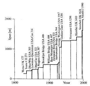
upper deck was in place between 1931 |
||||
Revolution - with its scientifically pro- |
and 1962. At the end of the 20th |
||||
portioned bridge designs - the longest |
Century the 2000 m span limit will be |
||||
spans have been achieved by suspen- |
approached by the Akashi Straits |
||||
sion bridges (Fig. 15). |
|
|
Bridge in Japan. |
||
First were the chain bridges like the |
|
||||
Menai Straits Bridge of 1826 with a |
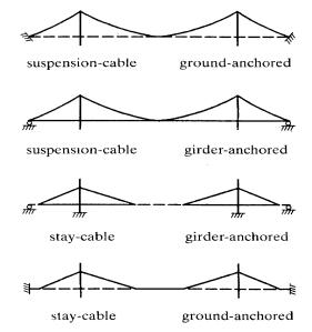
Structural Systems for the |
||||
span of 177 m. After that came the |
Longest Spans |
||||
development of the in situ cable |
Great spans are doubtless achieved |
||||
spinning |
technique |
with |
wires, |
||
whereby the erection problems were |
only with cable-supported bridges. In |
||||
significantly reduced. With the great |
principle the following cable-support- |
||||
bridge over the Saane River in |
ed bridge systems are known (Fig. 16): |
||||
Fribourg, Switzerland, in 1834 a span |
(a) Suspension bridge with cables |
||||
of 274 m was reached, and in 1848 the |
anchored in the ground: up to now this |
||||
ill-fated Ohio River Bridge at |
|||||
|
|||||
Wheeling, USA, was the first to reach |
is the system used for the longest spans. |
||||
the span of 1000 ft. (308 m). The |
|
||||
longest leap in the 19th century was |
(b) Suspension bridge with cables |
||||
certainly the 487 m long span for the |
|||||
anchored against the deck girder: used |
|||||
Brooklyn Bridge in 1883. With the |
only for small bridges and small spans, |
||||
construction of the George Washington |
because the girder must first be |
||||
Bridge in 1931 between New York and |
constructed on a scaffold. |
||||
New Jersey, O. H. Ammann showed a |
(с) Cable-stayed bridge with cables |
||||
new way to design suspension bridges. |
|||||
anchored in the deck girder: almost all |
|||||
He increased the record, span from the |
cable-stayed bridges are built with this |
||||
564 m of the Ambassador Bridge in |
system. The compressive force |
||||
Detroit to the unbelievable 1067 m, |
introduced into the girder by the cable |
||||
whereby in View of the high dead |
stays and the cantilevered construction |
||||
weight or rather the "cable stiffness" (a |
stage is critical limitations for the span |
||||
consequence of the great dead weight), |
length. |
||||
he greatly reduced the stiffening truss |
|
||||
and even concluded that he could |
|
||||
eliminate |
it entirely |
when |
only the |
|
|
was devoted to new developments in the construction of extremely long spans. The main problem for these bridges - as already noted - is their dynamic behaviour. This behaviour can be improved by an extra-wide deck, a streamlined deck cross section, a V-shaped arrangement of the hangers and by the placement of cable stays in the region near the pylons. In 1968, F. Leonhardt already emphasized the importance of a streamlined cross section and the effectiveness of V-shaped hangers [1]. References [2, 3 and 4] propose combinations of these measures. Reference [5] proposes a concept with spread pylons for the suspension cables, which most likely will present considerable difficulties in construction.
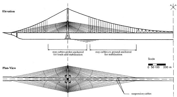
New Structural System for Extremely Long Spans
deck girder a sloping cable-stayed |
The construction sequence for this |
|
system carried by slender pylons |
system is relatively simple: |
|
which are supported by the central |
– erect the central pylon |
|
pylon. |
– install the suspension cables (the |
|
|
most difficult process of the erection of |
|
|
the bridge) |
|
|
– pull up the cable-stayed pylons. |
|
|
which are anchored with temporary |
|
|
and final cables to the central pylon |
|
|
– build the deck from the cable stays |
|
|
and the suspenders. |
|
|
The proposed concept considers nu- |
|
|
merous parameters, which for a bridge |
|
|
with an extremely long span, must he |
|
|
optimized specifically for each design. |
|
|
The following parameters are particu- |
|
|
larly important: |
|
|
– height of the central pylon, height |
|
|
and slope of the cable-stayed pylons |
|
|
– placement of the traffic lanes, rail . |
|
|
lines in the middle of the deck or |
|
|
placed one at each edge |
|
|
– number of suspension cables: two or |
|
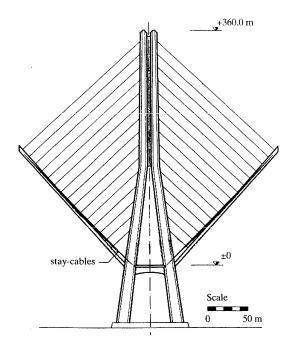
Fig. 17 |
three |
|
By means of a cable connection with |
– form of the deck cross section and |
|
length of the deck segments |
||
the central pylon, the danger of |
– length of the region with V-shaped |
|
buckling in the slender cable-stayed |
hangers |
|
pylons will be practically eliminated. |
– construction: installation of the |
|
In the vicinity of the pylon, the cable- |
suspension cables, erection of the |
|
stayed system will also carry the |
deck. |
|
vertical load; on the central part of the |
|
|
span the more widely spaced cable |
WHAT COMES NEXT? |
|
stays serve primarily for the dynamic |
|
|
stabilization of the deck. If the |
At the present time, steel is clearly the |
|
compressive force in the deck must be |
most suitable material for 3000 m |
|
limited, then at least a part of the sta- |
spans. This could change, however, if |
|
bilizing cables can be anchored (like |
synthetic materials such as carbon |
|
he suspension cables) in the ground |
fibers prove reliable in |
construction |
(Fig. 18). |
and the cost of their production were to |
|
|
||
|
decrease substantially. |
For spans |
|
greater than 3000 m, new materials |
|
that are signific antly lighter than steel are essentia l.
As spans increase beyond 3000 m, it will become necessar
y to build an increasingly larger proportion of structural components completely or partly of synthetics.
|
|
|
Fig. 18 |
|
The first components to be built of |
coefficients of thermal expansion are |
|||
synthetic materials will be long |
different for these two materials, the |
|||
stabilizing cables. For these cables, the |
stresses redistributed from one material |
|||
ideal axial stiffness, which is a |
to the other due to change in |
|||
function of sag, is extremely important |
temperature are small compared to |
|||
[6]. For long spans, lighter carbon fiber |
stresses due to load. |
|||
cables can achieve the same stiffness |
The last step in the development of |
|||
with a much smaller cross section than |
bridges of extremely long spans may |
|||
heavier steel cables. |
|
|
be not only the entire cable system of |
|
As spans increase, it will become |
synthetic materials, but also the girder. |
|||
necessary to use synthetic materials for |
The first tests of girders made of syn- |
|||
the main suspension cables. Already |
thetics are already under way [7]. The |
|||
for 3000 m spans, the weight per unit |
proposed basic structural concept for |
|||
length of suspension cables is roughly |
the design and construction of the tow- |
|||
equal to that of the girder it supports. |
ers would remain valid in such a case. |
|||
The unit weight of the cables should |
CONCLUDING REMARKS |
|||
not increase as spans are increased |
||||
even further. This can be avoided most |
|
|||
simply through the use of a hybrid |
Simple extrapolations of rather |
|||
cable system, in which cables are |
conventional concepts usually do not |
|||
composed of synthetics and steel |
lead to great progress in technological |
|||
acting |
together. |
Although |
the |
development. This is true as well for |
extremely long spans in bridge |
[3] CASTELLANI, A. The Project for |
|||||||||
structures. Because |
today |
lightweight |
the Bridge over the Messina Strait, |
|||||||
high strength materials are not yet |
ibid., pp. 517-527. |
|
||||||||
inexpensive and cannot yet be |
[4] WALTHER, R., AMSLER, D. |
|||||||||
produced |
in |
sufficient |
quantity, |
Hybrid Suspension Systems for Very |
||||||
economical and practical designs for |
Long |
Span |
Bridges: Aerodynamic |
|||||||
extremely |
long |
spans |
require |
Analysis and Cost Estimates, ibid., pp. |
||||||
unconventional structural systems. The |
529-536. |
|
|
|||||||
proposed structural concept, with its |
[5] GIMSING, N.J. Suspended Bridges |
|||||||||
relatively |
simple |
construction |
with Very Long Spans, ibid., pp. 489- |
|||||||
technique, is certainly suited for this |
504. |
|
|
|
||||||
design problem. It is suitable, not only |
[6] MEIER, U. Carbon Fiber- |
|||||||||
for great spans but also for narrow |
Reinforced |
Polymers: |
Modern |
|||||||
bridges with shorter spans and espe- |
Materials in |
Bridge |
Engineering. |
|||||||
cially also for long span pipeline |
IABSE, Zurich, SEI1/1992, p. 7. |
|||||||||
bridges. |
|
|
|
|
|
|
(7) SEIBLE, E, BURGUENO, R. Ad- |
|||
REFERENCES |
|
|
|
|
vanced Composites in Cable Stayed |
|||||
|
|
|
|
Bridges. Seminar in Cable-Stayed |
||||||
[1] LEONHARDT, F. Zur Entwicklung |
Bridges, Miami, FL, Oct. 17-18,1994. |
|||||||||
aerodynamisch |
|
|
|
stabiler |
|
|
|
|
||
Hangebriicken. |
Die |
Bautechnik |
45, |
|
|
|
|
|||
Heft 10 und 11,1968. |
|
|
|
|
|
|
|
|||
[2] LACROIX, R., et al. 3000 Metres: |
|
|
|
|
||||||
We Can Make |
It! |
Proc. |
Int. Conf. |
|
|
|
|
|||
IABSE-FIP, Deauville, 1994, Vol. 1, |
|
|
|
|
||||||
pp. 505-515. |
|
|
|
|
|
|
|
|
|
|
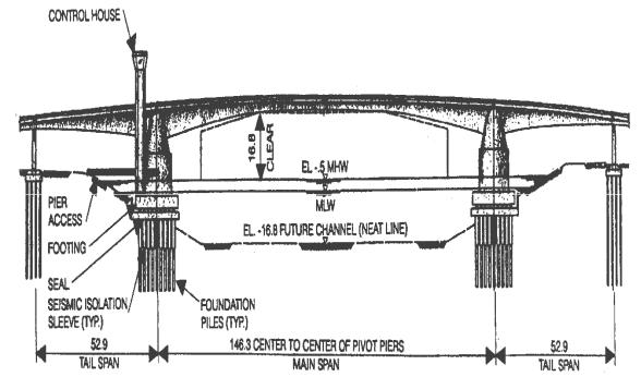
WEST SEATTLE SWING BRIDGE, SEATTLE, WASHINGTON |
||||||||||
John H. Clark, Vice Pres., |
|
|
|
portions of the industrial port area of |
||||||
Andersen Bjornstad Kane Jacobs, Inc., |
Seattle across one of its major shipping |
|||||||||
Seattle, WA |
|
|
|
|
|
|
channels. |
|
|
|
|
|
|
|
|
|
|
Prospects for widening the current-46 |
|||
PLANNING |
|
|
|
|
|
m wide ship channel to 76 m required |
||||
|
|
|
|
|
|
|
replacement of an existing bascule, |
|||
A double-leaf concrete swing bridge |
built in 1927. Navigation traffic in |
|||||||||
across the Duwamish River in Seattle, |
1994 |
required approximately 10 |
||||||||
Washington, represents a revival of a |
openings per day of the existing |
|||||||||
type of movable bridge long out of |
bridge, which provides 14 m of |
|||||||||
favor and incorporates new concepts in |
vertical clearance over high water. |
|||||||||
machinery |
and |
movable |
bridge |
Increasing the vertical clearance from |
||||||
technology. |
The |
bridge connects |
two |
14 m for the existing bascule bridge to |
||||||
17 m for the new bridge was predicted to be sufficient to reduce the number of openings to 7 per day average, primarily for large ocean-going barges and ships. Roadway traffic is predicted to reach 11000 vehicles per day, with approximately 15 % truck traffic.
Pedestrians and bicycles are also provided for on the new swing span, but are excluded from the high level bridge. The total structure width of 15.2 m provides for two traffic lanes and one combined bicycle/pedestrian way 3.66 m wide.
|
|
Fig. 19 |
|
The swing bridge alignment was |
set by the column of the high level |
||
placed on the existing bridge align- |
bridge. Once the alignment was |
||
ment to minimize required right of way |
chosen, the span lengths were fixed. |
||
and revisions to the existing street |
The west approach |
||
network. This alignment results in the |
length of 153 m is determined by the |
||
bridge axis being skewed approxi- |
need to cross over a railroad track and |
||
mately 45° to the channel. A total of |
an intersecting street. The east ap- |
||
nineteen different alignments and three |
proach length of 147 m was deter- |
||
basic structure types were evaluated |
mined by the maximum grade of 7% |
||
before selection of the swing bridge for |
and vertical curve lengths required for |
||
final |
design development. |
Other |
proper sight distance. Stair towers for |
structure types investigated in the |
pedestrian access are provided on each |
||
preliminary design stages were a |
approach. A control tower for the |
||
vertical lift bridge and a bascule |
bridge operator is adjacent to, but sep- |
||
bridge. |
|
|
arate from, the west pivot pier. The |
The 146 m span center-to-center of |
control tower is a 36 m high structure, |
||
pivot piers (Fig. 19) for the swing |
so that the bridge operator has unre- |
||
bridge was established by the width of |
stricted view of the channel and all of, |
||
the open west leaf and the location of a |
the approach roadway. |
||
column of the adjacent high level |
STRUCTURAL DESIGN |
||
bridge. The east pivot pier is then |
|||
placed |
symmetrically about |
the |
|
centerline of the proposed channel. |
The crossing site is near the mouth of |
||
The tail span length of 53 m was also |
the Duwamish River. Soils encoun- |
||

tered at the site range from hydraulic |
based. The location of the piers in the |
|||
fill and recent alluvial sands and silts |
sloping bank of the existing and future |
|||
to heavily pre-consolidated glacial till. |
channel created a problem of differing |
|||
Depth to the till varies from 15 m on |
transverse stiffness of the piles which |
|||
the west end of the project to 60 m on |
would have led to eccentricity between |
|||
the east end. Lenses of loose silt exist |
the center of mass and center of |
|||
erratically throughout the alluvium |
rigidity. These two problems were |
|||
layer. The loose surficial silts and hy- |
addressed by the new concept of "seis- |
|||
draulic fill are deemed susceptible to |
mic isolation" sleeves. |
|
||
liquefaction in major seismic events. |
Considerations in the choice for the |
|||
Densification by vibro-flotation was |
superstructure design were construc- |
|||
specified to prevent such liquefaction. |
tion economy, maintenance costs, traf- |
|||
Seismicity in the area is moderately ac- |
fic safety and aesthetic compatibility |
|||
tive. Seismic design criteria generally |
with the adjacent high-level bridge (a |
|||
followed the Guide Specifications for |
concrete box girder). Two designs |
|||
Seismic Design of Highway Bridges, |
were prepared and advertised for bids, |
|||
1983, of the American Association of |
a post-tensioned segmental concrete |
|||
State Highway and Transportation Of- |
box girder and a steel box girder with a |
|||
ficials, with appropriate modifications |
precast prestressed concrete deck made |
|||
for the unique structure. The basic |
composite after erection. Typical cross |
|||
seismic coefficient, amax is 0.30 g and |
sections of the concrete alternative are |
|||
the soil type is Type III. |
shown in (Fig. 20). |
|
||
The main piers and superstructure |
A major challenge in the design of the |
|||
comprise a structural unit which does |
concrete box girder bridge was control |
|||
not contain the "ductile element" upon |
of long-term deformations. Provisions |
|||
which the Guide Specifications are |
for control of both long-term and |
|||
|
short-term deformations included ad- |
|||
|
ditional post-tensioning beyond that |
|||
|
required for stress control, provision of |
|||
|
some unbonded tendons, provision for |
|||
|
additional |
future tendons, provisions |
||
|
for adjustment of approach span |
|||
|
elevation at the tail span joint, |
|||
|
provision for vertical adjustment of |
|||
|
each leaf as a whole, and |
|||
|
specifications |
requiring |
nearly |
|
|
simultaneous construction of the two |
|||
|
movable leaves. |
|
|
|
|
The first line of defense against |
|||
|
unwanted long-term deformation was |
|||
Fig. 20 |
the adoption of the principle of load |
|||
|
balancing |
for |
the design |
of the |