

2376
.pdftails throughout the design and planning of the crossing.
The rounded corners and reduced bolt connections of the main towers' columns and beams, as well as the configuration and surface finish of the anchorages, resulted from aesthetic considerations. The graceful configuration of the bridge is illuminated at night by white, green and coral pink lighting. The lighting pattern varies with the seasons and times of day. For its illu-
mination design, the Rainbow Bridge was awarded the Paul Waterbury Award of Distinction for Outdoor Lighting by the Illumination Engineering Society of North America.
Owner/Engineers: Metropolitan Expressway Public Corp. (MEPC), Tokyo
Construction duration: 6.5 years Service Date: August, 1993
THE TÄHTINIEMI BRIDGE, FINLAND
Esko Jarvenpaa, Technical Dir. Pekka Pulkkinen, Civil Eng. Suunnittelukortes AEK Ltd, Oulu, Finland
Reiner Saul, Managing Dir. Leonhardt, Andra and Partner, Stuttgart, Germany
Introduction
In 1988 the Finnish Roads Administration organised a design competition for a technically advanced bridge which would adapt well to the lake landscape near the city of Heinola. Heinola is one of the most beautiful cities in Finland, about 130 km north of Helsinki on the route to a lake area where many vacation cottages are located.
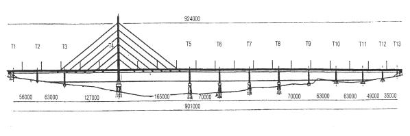
The winner of the competition, now known as the "Star of Heinola", is a single-pylon cable-stayed bridge (Figs. 33, 34). It is the largest bridge in Finland, with a total length of 924 m. The
main span is 165 m and the width of the deck varies from 22 to 30 m.
Fig. 33
Design Competition
The competition was limited to four Finnish bridge engineering companies. The design brief was very demanding. Among the most important parameters were the site, the difficult foundation conditions, the curvature of the roadway and the need to maintain freeflowing marine traffic, including a busy logging channel. Maximum water depth at the site is 24 m, and the bridge is situated in a natural lake landscape, near the town.
Ten proposals were delivered to the competition jury. Five were traditional composite girder designs; one was a
193
single pylon design and three were |
struts in the cross sections of two steel |
double-pylon cable-stayed designs. |
girder designs for this type. |
There was also one truss bridge pro- |
The cross section alternatives for the |
posal. |
cable-stayed bridge designs were a |
In the superstructures of the composite |
concrete box girder, a composite gird- |
girder bridges, reinforced compression |
er, a composite box girder and a com- |
slabs were used in the areas of the in- |
posite slab beam which was pre- |
termediate supports, and longitudinal |
stressed in two directions. |
prestressing in the deck slab. Due to |
The foundation solutions were very |
the considerable width of the deck that |
similar in all bridges. In deep water, |
was required, there were inclined steel |
composite steel pipe piles were used. |
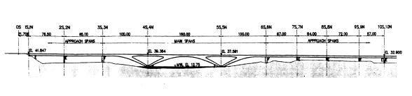
Fig. 34
Other supports were founded on soil or |
Deviating from Finnish load specifica- |
rock. The diameter of the piles varied |
tions, the full traffic load can be car- |
from 700 to 1500 mm. |
ried on one side of the bridge deck |
The winning design, with its single |
when there is simultaneously a special |
105 m high pylon, serves as a dramatic |
heavy truck on the other. If the cables |
gateway to the lake district of Finland. |
have to be changed in the future, only |
Its cable-stayed spans are placed over |
one edge lane has to be closed. Also, |
the open lake so that the heavy marine |
the pylon was designed for greater |
traffic can operate with minimal ob- |
wind loads than specified in the exist- |
struction. |
ing code. Crash loads of ships have |
Bridge Design |
been taken into consideration in the |
design of the intermediate support. |
|
|
The five middle supports are founded |
The client wanted to assure adequate |
on composite steel pipe piles; other |
traffic-handling capacity of the bridge |
supports are founded on soil or rock. |
far into the future as well as under ex- |
The steel piles were designed as a |
ceptional circumstances. Thus, it was |
composite structure with a 4 mm thick- |
decided that the bridge should be de- |
ness of the steel pipe wall allowed for |
signed for far heavier traffic loads than |
corrosion. The diameter of a pile is 813 |
current Finnish load codes specify. |
mm and thickness is 16 mm. Rein- |
194
forcing bars are placed in the uppersection of the piles.
The cross section of the deck is a traditional composite structure of two open girders. The girders are 3.2 m high I- beams (Fig. 33). There are crossbeams at 7 m centres. On the crossbeams there is a 1 m high secondary longitudinal girder. In the north part of the bridge, where the deck is 30 A wide, there are two secondary girders.
The cable crossbeams are inclined to the cable direction. Between the main girders, the cross section of the cable crossbeam is an open I-beam. The girders are stiffened with steel bars. Outside the main girders, the cable crossbeam is a composite box girder.
In the competition proposal, the pylon was a steel structure. In the general design, the costs of steel, composite and concrete pylon were compared. The concrete pylon proved to be the most economical.
The pylon is formed of two T-shaped hollow concrete towers which are joined together by two crossbeams. There is an elevator inside one tower and stairs inside the other. The horizontal geometry of the road has a curvature of R = 4000 m. This caused large horizontal forces on the towers. Therefore, the pylon was not placed centrally to the deck cross section, but with an eccentricity of 0.6 m. Due to this placement, the horizontal forces, and hence, the number of steel piles decreased considerably.
The bridge has 24 factory-fabricated parallel wire cables. The cables consist of 7 mm steel wires (253-403/cable) injected with grease inside a high den-
sity polyethylene pipe that is covered with white Tedlar tape. The pylon and cables are illuminated at night.
The fixed bearing of the bridge is at the southern abutment. It is a hinged structure, where horizontal forces are transferred large steel bars.
Construction
The piling and the concreting of the foundation slabs and columns took 14 months. The joint welding of the steel girder sections and the launching were completed in one year. The largest concrete works, such as towers and deck slabs, were placed in summer, because the temperature in winter can be as low as -25 °C.
At the beginning of the construction period, the design for the pile foundation was changed to a caisson structure. The caissons were built in a dammed trough on the north side of the bridge. The caissons were floated into position and the piling work was done through access holes in the caisson slab. Finally, the piles and the inner part of the caisson were cast in dry conditions. Except for the slab of supports T3 and T9, all casting work on the substructure was done in dry conditions. The casting of pile slabs succeeded well and there were no faults typical of underwater concrete casting. The steel girders of the superstructure were launched from both abutments and joined by welding between supports T5 and T6. Three auxiliary piers had to be built for the cable:stayed spans during launching. The top of the girder was lifted on a pontoon when
195
the spans exceeded 70 m. The launching bearings were vertically adjustable because the girder was very stiff. The longest beam sections were 42 m long and the maximum weight was almost 80 t.
The bridge was originally designed using steel grade Fe 355 E, but the steel contractor and steel manufacturer proposed to change the steel grade of the support sections of the girder to a new thermomechanically manufactured S 420 ML steel. Using this material, the contractor slightly reduced the weight of the girder and benefited from the superior welding properties of the new steel grade. The total amount of steel in the superstructure is about 50501.
The towers of the pylon were cast using a climbing formwork, with the height of one casting section being 4.15 m. The longitudinal reinforcing bars were jointed with screw sleeves.
The crossbeams between the towers and the cable anchor areas were pre: stressed. The surface of the concrete tower had to meet stringent quality requirements. A textile covering was placed on the formwork surface to enhance the strength of the concrete surface and to reduce air blisters. A green concrete paint was applied to the surface of the pylon.
Construction of the pylon was complicated because it has three inclined walls. Therefore, the scaffolding had to be adjusted at every stage. The reinforcing of the cable anchor area was difficult because of restricted space. The temporary support structure of the
upper crossbeam was also difficult to install and there were problems to stabilise it. Nevertheless, the pylon was completed on schedule and all casting work was completed before winter.
The deck slab of the superstructure was cast using two movable scaffolding units. The longest casting section was 24 m. The slab was prestressed transversely in two equal stages.
The stay cables were installed from the bottom upwards. Cable stressing was accomplished using four jacks at the level of the deck slab. The cables were stressed in pairs. The total weight of stay cables is 214 t. They were tested against fatigue and ultimate load, the test cable being the largest cable of the bridge. In the fatigue test, where a 5 m long test Cable was loaded 2 million times with a stress variation of 193 MPa, only 9 wires broke. After this test the same cable was stressed up to the breaking load, 24.6 MN.
Client:
Mikkeli Road District
Design:
Suunnittelukortes AEK Ltd, with Leonhardt, Andra and Partner
Main contractor: WT Corporation Ltd
Steel contractor: PPTH Steel Ltd
Construction duration: January 1991 to November 1993
196
THE PITAN BRIDGE, TAIWAN |
|
|
|
|
|||
Kwong M. Cheng |
|
|
|
- meet all freeway design and perfor- |
|||
Pres., |
OPAC Consulting |
Engineers, |
mance requirements of the Northern |
||||
San Francisco, CA, USA |
|
|
Taiwan Second Freeway |
||||
Introduction |
|
|
|
- be aesthetically pleasing, construc- |
|||
|
|
|
table, and economical |
||||
|
|
|
|
|
- require minimum maintenance. |
||
To alleviate traffic congestion near |
The following factors were considered |
||||||
Taipei, in 1985 the Taiwan Area Na- |
in the selection of the bridge type: |
||||||
tional Freeway Bureau planned the |
- |
Structural systems issues such as |
|||||
construction of the 108 km long North- |
bridge piers, span lengths and ar- |
||||||
ern Taiwan Second Freeway. The ma- |
rangement, |
foundations, vertical and |
|||||
jority of the Second Freeway's align- |
horizontal clearances, capacity to resist |
||||||
ments are on grade, on embankments, |
horizontal forces and seismic actions, |
||||||
in tunnels, or on viaduct structures. At |
etc. |
|
|||||
several locations, |
however, |
obstacles |
- |
Aesthetic issues such as the overall |
|||
were identified that required special |
appearance of the bridge, its com- |
||||||
bridges. The Pitan Bridge spans one of |
patibility with the surrounding land- |
||||||
these areas. |
|
|
|
scape and with existing built facilities |
|||
The Pitan Bridge, actually two nearly |
- Construction issues such as the con- |
||||||
parallel bridge structures, is located |
struction method, equipment, con- |
||||||
about 15 km south of Taipei. It con- |
struction time and the capabilities of |
||||||
nects typical low-level viaducts to |
a |
local contractors |
|||||
tunnel. Both bridge units have a total |
- Cost issues such as the cost of relat- |
||||||
length of approximately 800 m, a 750 |
ed |
works, |
of maintenance and the |
||||
m radius curvature and a slope of ap- |
cost of the bridge itself. |
||||||
proximately 1%. The Pitan Bridge has |
Four bridge types consisting of varia- |
||||||
become a landmark in this suburban |
tions on girder-and-arch designs were |
||||||
area of Taipei. |
|
|
|
identified as potentially meeting the |
|||
Selection of the Bridge Type |
|
above design considerations. |
|||||
|
The selected bridge type consists of a |
||||||
|
|
|
|
|
post-tensioned cast-in-place concrete |
||
The design of the Pitan Bridge was |
box girder bridge deck supported on |
||||||
based primarily on the 1983 AASHTO |
delta-shaped reinforced concrete box |
||||||
Standard Specification for |
Highway |
piers, which are joined together at the |
|||||
Bridges, the 1987 AASHTO Design - |
centre of the main span to form an |
||||||
and |
Construction |
Specifications |
for |
arch. This scheme adapts well to the |
|||
Segmental Bridges (No. 2 Draft), and |
constraints of the site and provides a |
||||||
local design codes. Among the general |
stiff, strong bridge with a clean, effi- |
||||||
constraints and concerns that guided |
cient, and very modern appearance. |
||||||
the design of the bridge, it had to: |
|
|
|
|
|||
197
Basic Layout |
spans totalling 781.5 m, with a 160 m |
|
main span. The northbound bridge has |
The two almost parallel bridge struc- |
an additional simple span of 21.7 m |
tures have nearly identical structural |
(Fig. 35). |
layouts. They each consist of nine |
|
Fig. 35
Expansion joints have been kept to a |
determine the dimensions of the main |
minimum, located only at the extreme |
structural elements of the bridge: the |
ends of the structure. The four main |
cross section, the longitudinal system, |
bridge piers (3, 4, 5 and 6) are fixed to |
the pier shafts, footings and piles. |
the girder and footings with monolith- |
Superstructure Design |
ic, moment-resisting connections. The |
|
smaller piers and the abutment are |
|
fixed to their footings only and support |
Detailed design and analysis made use |
the girder through bearings that are |
of more refined analytical tools in or- |
fixed transversely, having some lim- |
der to verify the preliminary design. |
ited freedom-to slide longitudinally. |
The following tasks were performed: |
This combination of few expansion |
- development of structural models for |
joints and high pier fixity was evaluat- |
service-load analysis |
ed for serviceability under the required |
- evaluation of design values for mo- |
seismic excitation, as well under the |
ment and shear |
influence of creep and shrinkage in the |
- transverse and three-dimensional |
concrete, and temperature change in |
considerations |
the structure. The piers and founda- |
- pier moments, shears, and axial |
tions provide enough flexibility so that |
forces |
the time-dependent strains and tem- |
- thermal effects. |
perature strains of the concrete, accu- |
The bridge superstructure consists of a |
mulated over the entire girder length |
single cell box girder (Fig. 36). The di- |
between expansion joints, cause ac- |
mensions of the box girder were de- |
ceptably small bending stresses in the |
signed to comply with the strength re- |
piers and axial stresses in the girder. |
quirement as well as provide space to |
The preliminary design made use of |
house the necessary prestressing ducts. |
simple and rational analytical tools that |
The main span girder depth varies |
have proven reliable for many struc- |
from 8.882 m at the face of the delta- |
tures. The following were considered |
shaped pier to 3.5 m at mid-span, and |
at this stage of the design in order to |
is prestressed longitudinally with can- |
198
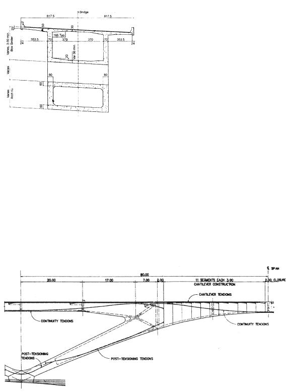
tilever tendons in the top slab and con- |
mid-span and over the pier to resist su- |
tinuity tendons in the webs. All pre- |
perimposed dead load, live load, creep, |
stressing is grouted in ducts embedded |
and temperature moments. Each of |
in the slabs and webs of the girder. |
these tendons extends over the full |
|
length of a span, and is anchored in the |
|
diaphragm walls over the pier. |
|
The deck transverse prestressing is di- |
|
mensioned to resist transverse bending |
|
from dead load and live load. The gird- |
|
er cross-section reinforcement includes |
|
a grid of mild steel bars in each direc- |
|
tion on each face of each structural el- |
|
ement. |
|
The delta-shaped piers are designed to |
|
reduce the length of the main span, |
Fig. 36 |
thus allowing the relatively slender |
The top deck longitudinal prestressing |
box girder to meet the strength and |
is dimensioned to resist all structural |
stiffness demands on this bridge. They |
dead loads during cantilevering, as |
are designed as wall-type elements |
well as construction loads and the |
with post-tensioning to provide a re- |
weight of the travelling formwork. All |
sidual compressive stress under com- |
anchorages are located in the well- |
bined axial force and bending for all |
confined and reinforced intersection |
service load conditions. The schematic |
fillets at the tops of the webs. |
prestressing layout of the main span is |
The web longitudinal prestressing is |
shown in Fig. 37. |
dimensioned to provide adequate mo- |
Seismic Analysis and Design |
ment capacity and stress control at |
Fig. 37
199
Initial, seismic analyses were performed in accordance with the local seismic design criteria. These analyses provided controlling conditions for design of the piers and foundations.
A more refined analysis using earthquake response spectrum developed for the vicinity of the site, was used later to verify structural dimensions and reinforcement requirements.
Substructure Design
Each pier consists of a four-walled cellular reinforced concrete shaft, heavily reinforced to form a ductile cellular element. All fixed piers participate in providing the required capacity to resist seismic and horizontal forces. For transverse seismic loads, the piers behave as cantilevers, with significant moments developed at the bottom only. For resisting longitudinal seismic excitation, the main piers behave as members in a rigid frame. The creep, shrinkage, and temperature deformations of the superstructure are adequately accommodated in the monolithic piers by the flexibility of the foundations and the pier shafts.
The basic cross section of the main piers continues through the depth of the box girder cross section to provide diaphragms capable of developing the plastic moment of the pier into the girder. These diaphragms also provide a convenient location for anchorage of the longitudinal prestressing tendons in the superstructure.
The abutment is designed as a conventional cantilever wall which supports the bridge girder on sliding bearings. The footing blocks supporting the piers
were designed for the static dead and live impact loads and the seismic loads such that the movements at the base of the piers are within allowable limits and no plastic hinges develop below the ground surface.
Foundations consist of 2.0 m diameter drilled, cast-in-place, reinforced concrete piles, supporting reinforced concrete footing blocks. The piles, up to 14 m in length, act as friction piles with some limited end-bearing support.
Analysis and Modelling
Constructability will largely determine the success of a project. Therefore, a thirty-eight step stage-by-stage analysis of the bridge was performed to validate the time-dependent behaviour of the construction sequence. The analysis included:
-development of structural computer models for construction procedure
-evaluation of stresses and deflections at critical construction stages
-evaluation of stresses and deflections over the service life of the bridge. The bridge was modelled using a commercially available general-purpose structural analysis program which is capable of static and dynamic analysis of finite element models for a wide range of structure types.
All important structural features of the bridge were modelled, including the piers, the box girder, and the deltashaped piers. The girder was modelled as a line of frame elements representing the entire cross section, oriented along the centroidal axis of the prototype girder. The piers were modelled
200
similarly, including semi-rigid elements in the pier-girder intersection. The intersection zone between the delta-shaped piers and the girder was modelled by a separate finite element
model in order to capture the stress distribution between the diaphragms and the webs in this area.
ROOSEVELT LAKE BRIDGE, GILA COUNTY, ARIZONA
Maurice D. Miller, Civil Eng. |
ing hundreds of miles to the route. Al- |
HTNB Corp., Kansas City, MO |
though traffic congestion was im- |
Crossing Roosevelt Lake |
portant, the deciding factor for the new |
Roosevelt Lake Bridge was flood pro- |
|
|
tection. When the US Bureau of Rec- |
Located in Gila County, a rugged area |
lamation raised the dam by 23.5 m to |
of east-central Arizona, Roosevelt |
provide additional protection to Phoe- |
Lake is a hydroelectric reservoir used |
nix and the Valley of the Sun, it re- |
for flood control, irrigation and recre- |
moved State Highway 188 from the |
ation. It is midway between the cities |
dam. |
of Globe, which is the county seat, and |
Bridge Type Selection |
Payson, in a ranching and recreational |
|
area. State Highways 88 and 188 con- |
|
nect the two major cities. From Globe, |
Located about 305 m upstream of the |
Route 88 winds northwest through de- |
dam, the new Roosevelt Lake Bridge is |
sert canyons and along the south-west |
just below the confluence of the Salt |
shore of Roosevelt Lake to a masonry |
River and Tonto Creek. Here, the Salt |
dam, where it connects with Route 188 |
River just begins the erosion of its |
and continues west and north to Pay- |
canyon through the Mazatzal Moun- |
son. |
tains. The steep-walled features of the |
The one-lane road traversing the dam |
canyon were ideal for the construction |
across Roosevelt Lake had not been |
of the world's highest masonry dam, |
improved since construction of the - |
creating a lake 300 m wide and 60 m |
dam in 1911. Travel across the dam |
deep at the proposed crossing. |
was slow and treacherous, with abrupt |
The Arizona Department of Trans- |
90° blind corners. When two cars met |
portation based its selection of the best |
on the dam, one had to yield the right- |
type of bridge for the crossing on eco- |
of-way and back up, a gesture that was |
nomics. Because of the steep valley |
not always made willingly by the local |
walls and the deep valley floor, under- |
ranchers. |
water foundations were determined to |
Because of the narrow and crooked |
be too costly. The two-lane bridge |
route over the dam, vehicles over 9 m |
would have to span the lake with foot- |
in length were prohibited. Commercial |
ings on each shore. Two engineering |
traffic between Globe and Payson was |
firms prepared complete construction |
forced to detour through Phoenix, add- |
plans for two alternatives: a steel box- |
201
rib-through-arch and a concrete stayed girder bridge.
The box-rib-through-arch was selected for the steel alternative based on an indepth study of three steel bridge types: trussed-through-arch, box-rib-through- arch, and cable-stayed girder. The twisting alignment required for the mountainous terrain made it difficult to get a tangent alignment long enough to accommodate minimum-length back spans for the cable-stayed and trussed arch bridges.
The arch span was the most economical. It adapted readily to the curved alignment of the approach structures and had superior aerodynamic properties. The welded steel arch was the overwhelming favorite of most bidders. It was bid at 30% less than the concrete alternative.
Arch Rib Design
Existing terrain and future lake levels were important factors in establishing the arch rib geometry. The arch springline is at Elevation 649.5 m, well below the 200-year flood elevation of 663 m. To keep the steel arch above water, the lower 158 m of the arch rib is made of concrete. The resulting composite steel-concrete structure consists of the following sections: 21.6 m of concrete rib, 323 m of steel rib, and 21.6 m of concrete rib, for a total arch rib length of 366.4 m and an arch span of 329 m.
The steel and concrete portions were made continuous by anchoring a base plate at each of the steel-concrete con-
nections. This required 32 MN of prestress force at each base plate.
The geometry of the entire arch rib optimizes the use of material through the length of the rib. The depth of the steel box section varies from 2.44 m at the crown, where compressive forces are the smallest, to 4.27 m at the base, where compressive forces are the greatest. The shape of the arch rib was also established to minimize the dead load bending stress in the arch. The resultant shape is defined by both second order and fourth order curves, making the entire arch appear smooth and continuous.
The steel arch rib section is made up of two 1.2 m-wide flanges with two web plates that vary from 2.44 m at the crown to 4.27 m at the base plate. The webs of the box section are stiffened by two T-sections welded to each web. The stiffeners are continuous and participate fully in carrying the various loads. Sixteen longitudinal fillet welds, over 13.4 m long, were required to connect the flanges and the stiffeners to the webs.
Stability against global buckling and transmission of wind loads for the arch rib, which is 15.2 m center-to-center, was achieved through the use of a K- bracing system fabricated from structural tubing and welded box sections. The selection of the K-bracing was based on both first-cost and life cycle costs. The K-bracing required 901 less steel and reduced wind deflections to half as much as those caused by a comparable Vierendeel system. The closed tubular sections were selected to minimized corrosion due to entrap-
202