

2376
.pdf-The concrete and steel composite Composite Construction
deck, with concrete access spans on |
The second major point in the design |
close supports extended at a distance |
of the Normandie Bridge is the combi- |
of 116 m from each pylon in the cen- |
nation of prestressed concrete and |
tral span, as well as the rigid connec- |
steel. Composite designs, where con- |
tion between deck and pylons, in- |
crete and steel are used to their greatest |
creases the structure's rigidity. Wind- |
efficiency, are strongly endorsed by |
induced deflections are drastically re- |
the designers of the Normandie Bridge. |
duced. Alan Davenport compared the |
The Normandie Bridge combines con- |
deformability of the Normandie Bridge |
crete and steel for the design of the |
with the Littlebelt suspension bridge - |
deck, prestressed concrete in the access |
also efficiently built with a streamlined |
spans, on close supports, with an ex- |
deck based on the English experience |
tension in the main span on both sides. |
and a main span of only 600 m - and |
Only the central part of the m, in span |
concluded that the Normandie Bridge |
is an orthotropic steel box girder, much |
behaves like a cable-stayed bridge with |
lighter (9 t/m, instead of the usual 45 |
a much shorter main span and is much |
t/n) to limit the cable size. The use of |
more rigid than a suspension bridge |
concrete in the access spans reduces |
with a span of 500-600 m. |
total costs and increases the bridge's |
|
rigidity, as well as the back staying ef- |
|
ficiency of all rear cables. |
|
This efficient combination of concrete |
|
and steel in cable-stayed decks had |
|
been used before for the design of the |
|
Tampico Bridge in Mexico (360 m, |
|
1988) and of the Ikuchi Bridge in Ja- |
|
pan (490 m, 1991). And prior to that, |
|
much valuable experience had been |
|
gained about using various materials, |
|
such as traditional and lightweight |
|
concrete, in Dutch bridges built by the |
|
cantilever method (Nijmegen bridges, |
|
around 1970). The experience gained |
|
in using different weights for a specific |
|
structural purpose proved to be ex- |
|
tremely useful (the bridges at Ott- |
|
marsheim and Tricastin and the cable- |
|
stayed bridge over the Elorn River). |
|
The Normandie Bridge also uses a |
|
composite design for the upper part of |
|
the pylons, where cables are anchored |
Fig. 29 |
(Fig. 29). It is far more efficient to de- |
183
sign a steel anchorage box to anchor |
High Performance Concrete |
the cables, since steel plates easily car- |
|
ry tensile stresses from back-stays to |
|
cables suspending the main span. In |
The main advantage of high perfor- |
addition, it is much easier to fabricate |
mance concrete for standard and me- |
these steel anchorage boxes - or the |
dium span bridges is substantially en- |
elements which will constitute them - |
hanced durability. But for heavily |
in a factory than on site in concrete |
loaded elements, such as the pylons of |
100 or 200 m above ground. To |
cable-stayed bridges with long spans, |
achieve the proper geometry, it is nec- |
or the concrete deck of the Normandie |
essary to precisely adjust the position |
Bridge, which has to balance high |
of steel elements ants which are later |
stresses from wind effects, high perfor- |
completed by concrete walls. |
mance concrete has great structural |
Probably the first application of this |
advantages. |
technique was in Belgium, for the con- |
All concrete on the Normandie Bridge |
struction of the Ben Ahin and Wandre |
contains silica fume for a characteristic |
Bridges, designed by Rene Greisch |
strength of 60 MPa. This allowed for a |
ond Jean-Marie Cremer. The idea was |
reduction in the cross section of the |
used again for the Evripos Bridge in |
concrete in the pylons and deck and |
Greece and for the Chalon-sur-Saone |
thus a reduction in weight and founda- |
Bridge in France. The problem was |
tions. |
more complex in the Normandie |
Erection of the Access Spans |
Bridge, with the transverse inclination |
|
of cables. A design was developed |
|
with Jean-Claude Foucriat, introducing |
The erection of access spans on both |
horizontal prestressing tendons to press |
banks required the contractors to de- |
the concrete walls against the steel an- |
velop a new technology. Classical |
chorage boxes to help the transfer of |
erection techniques, with Teflon pads, |
vertical forces from steel to concrete. |
would have produced very significant |
The steel anchorage tower was divided |
horizontal forces due to friction (up to |
into 21 elements (the lower one being |
5%) and to the slope of the access |
divided into two half-elements) to be |
ramp (6%). For this reason the initial |
lifted by the site crane (capacity: 20 t), |
design did not use the incremental |
and welded on site. The typical ele- |
launching method, although it was of |
ment was designed to anchor a pair of |
great interest due to the complex cross |
cables on each side. The main plates |
section shape and to the high rein- |
were divided in ties for the transfer of |
forcement ratio necessary to resist |
forces from the main span to back- |
wind forces. |
stays in order to lighten the elements, |
To be able to use it despite the slope, |
reduce in situ welds and facilitate ac- |
the contractors invented a so-called |
cess from the lateral cells of the pylon |
«staircase» method for horizontal span |
- with a lift - to the anchorages. |
launching. The deck is supported on |
184
each pier by two trapezoidal blocks - |
pier |
with |
the |
incrementally |
|||||
one on each side - which can slide |
launched typical spans. |
|
|||||||
horizontally on the pier. This move- |
The steel part of the main span, 624m |
||||||||
ment is permitted by special bearings, |
long, has been erected by the cantile- |
||||||||
made of a series of small rollers, on |
ver method from the completed access |
||||||||
top of the pier. After the forward |
spans with the help of a mobile derrick |
||||||||
movement, the deck is lifted by jacks |
to lift the successive segment 19.6 m |
||||||||
commanded from a central computer |
long, on |
each bank. |
|
||||||
and the trapezoidal blocks are pushed |
A New Generation of Cables |
||||||||
backwards, ready for a new launching |
|||||||||
step. The launching operation proceeds |
|
|
|
|
|||||
by successive launching steps: 15 cm |
The preliminary design called for |
||||||||
horizontally and then 9 mm vertically |
locked coil cables, which were consid- |
||||||||
to correspond to the slope of 6%. |
ered very well adapted to such long |
||||||||
Such a procedure was only made pos- |
spans, but which arc unfortunately |
||||||||
sible by the use of a series of sensors, |
very heavy. Their erection cost thus |
||||||||
to control horizontal and vertical |
proved prohibitive. |
|
|||||||
movements on all supports, and of a |
For this reason, the contractors pro- |
||||||||
central microcomputer |
which could |
posed alternative cables made of indi- |
|||||||
command |
horizontal |
and |
vertical |
vidually protected strands of hot-dip |
|||||
movements. It was of special impor- |
galvanised wires which were re-drawn |
||||||||
tance, of course, that vertical move- |
to keep all their structural characteris- |
||||||||
ments be the same on all supports at |
tics. After coiling and after the corre- |
||||||||
any time. |
|
|
|
|
sponding thermal treatment, the voids |
||||
In addition, this new technique reduces |
between wires were filled with oil wax |
||||||||
the |
necessary |
manpower |
during |
to repel any water. The strand was then |
|||||
launching, since control is only n nec- |
protected by extruded high density |
||||||||
essary at supports, which can be dome |
polyethylene at least 1.5 mm thick. |
||||||||
at the central command from, meas- |
These strands were placed and ten- |
||||||||
urements obtained by sensors or video |
sioned one-by-one. Individual place- |
||||||||
cameras. |
|
|
|
|
ment was extremely economical, but |
||||
Erection of the Main Span |
|
tensioning required a new technique, |
|||||||
|
already developed by the cable sup- |
||||||||
|
|
|
|
|
|
plier for the erection of three bridges: |
|||
The 116 m long concrete cantilever |
the Arrade and Guadiana Bridges in |
||||||||
which extends the side spa is in the |
Portugal, and the Chalon-sur-Saone |
||||||||
main one on each bank, and the 96 m |
Bridge in France. The fast strand of |
||||||||
long last side span have been built by |
each cable is tensioned to a computed |
||||||||
the balanced cantilever method from |
value and equipped with a pressure cell |
||||||||
the pylon with the help of temporary |
which gives the tension at any time. |
||||||||
stays. In the last side span, the closure |
Each new strand, when installed, is |
||||||||
was |
made |
6 m |
before |
r 'aching the |
tensioned to have exactly the same ten- |
||||
185
sion as the pilot strand at that precise moment, which is given by the cell. All strands thus receive the same tension, which is the desired one if the initial tension of the pilot strand had been appropriately computed. If not. an adjustment is made the same way. This process is not susceptible to influences from temporary operations, such as the movement of construction equipment.
Finally, cables received an external duct made of a series of two half-ele- ments which are forced into each other. These ducts are not for corrosion protection; they are air and water permeable. They aim at reducing drag forces and avoiding rain-induced vibrations of the cables. In addition, they totally eliminate the vibrations of strands in the bunch which makes each cable, which are produced by wind interaction between strands by a kind of "wake" effect.
The purpose is totally different in the Normandie Bridge: due to the very, long span of the bridge, the main vibration period for vertical bending would have been of the same magnitude as the vibration period of the longer cables, 4.5 s, compared to about 4.0 s. In this situation, it was feared that cable vibrations would be induces by the deck movements. Interconnecting ropes were designed to totally change the vibration periods of cables, at least transversally, reducing them to 1.25 s and less.
Four ropes connect all cables in each plane of stays. Their tension was selected to avoid de-tensioning from vibrations produced by wind turbulence. Their constitution is composite, with steel and plastic to increase fatigue resistance because it is obviously difficult to simultaneously achieve a high damping coefficient and a high fatigue resistance.
Interconnecting Ropes |
Concluding Remarks |
In his design for the Messina Straits, Fritz Leonhardt envisioned connecting all cables in each plane of the cables by tying ropes, which aimed at increasing the apparent modulus of elasticity of the suspension, lowered by sag effects in long cable-stayed spans. In some other bridges, such as the Faro Bridge in Denmark or the two cablestayed bridges of the Kojima-Sakaide route of the Honshu-Shikoku link, ropes were, installed to limit cable vibration which was rain-induced in the Faro Bridge and coming from the wake effect in the Japanese bridges.
The design and construction of very large bridges which go beyond existing limits require the strongest determination from the Owner, who must invest enormous confidence in, and support of, the engineers in charge. The most dangerous tempests that audacious projects face are not produced by wind on site, but by antagonistic opinions that find a willing audience.
The success of the Normandie Bridge is due in large part to the confidence and support that the project received from the Owner, the Road Director and the local authorities. Some organi-
186
sational aspects and some episodes |
proved the performed analyses and |
|||
during construction indicate the deci- |
recommended some additional wind |
|||
sive importance of human factors. |
tunnel, tests, the results of which were |
|||
The Owner gave the design engineers |
even more favourable than the first |
|||
total responsibility for the design and |
evaluations. This confirmation of the |
|||
granted them complete freedom to as- |
design helped the project very much, |
|||
semble the design team. Under these |
and from the summer of 1991, all con- |
|||
circumstances, improvements could be |
tractors worked with enthusiasm and |
|||
introduced at each step of the project, |
energy to complete the bridge on |
|||
with no consideration other than effi- |
schedule, within budget and up to the |
|||
ciency. This is far superior to design |
prescribed standards of quality. |
|||
competitions, now preferred by some |
Any decision can be questioned, any |
|||
administrations, where projects can be |
action criticised. The clear conclusion |
|||
selected based not always on structural |
is that a complex and ambitious project |
|||
; aspects, and where designers can be- |
like the Normandie Bridge cannot be |
|||
come prisoners of their initial sketches |
successfully realised without a strong |
|||
and of premature options and deci- |
Project Manager - as Bertrand Derou- |
|||
sions. |
|
baix has been for this project -to guide |
||
Although there was no public money |
it over the years from conception to |
|||
in the Normandie Bridge, the French |
completion, even |
when |
questioned |
|
government had to approve the project. |
from many sides. Going further than |
|||
The Road Director at the time, lean |
ever before in any given field calls for |
|||
Berthier, decided to invite an as- |
courage. The Owner and the local au- |
|||
essment of the design by an interna- |
thorities remained totally confident in |
|||
tional group of experts: Marcel Huet |
the design and in the engineers in |
|||
(Project Manager of the Tancarville |
charge, even in difficult times. This |
|||
Bridge), Henri Mathieu, |
Charles |
was decisive for success; complex |
||
Bngnon, Roger Lacroix, Rene W'alther |
structures cannot be built with hesita- |
|||
and Jorg Schlaich. This group pro- |
tions and doubts! |
|
|
|
posed various amendments, some of |
References |
|
|
|
which were included in the final de- |
|
|
||
sign. |
|
|
|
|
Nevertheless, some engineers from one |
[1] VIRLOGEUX. M.; FOUCRIAT, |
|||
of the erection contractors considered |
J.-C; DEROUBAIX, B. Design -of the |
|||
the wind forces to have been un- |
Normandie Cable-Stayed Bridge near |
|||
derestimated and, thus, the safety ques- |
Honfleur. Proc. of the Int. Conf. on |
|||
tionable. The debate became public, |
Cable-Stayed Bridges, Bangkok, pp. |
|||
even international. |
|
1111-1122, November, 1987. |
||
The Owner and the Road Direc- |
[2] V1RLOGEUX, M. Projet du Pont |
|||
tor decided to consult Alan Davenport |
de Normandie, Conception generate de |
|||
to evaluate the wind tunnel tests and |
I'ou-vrage. Proc. of |
the |
13th IABSE |
|
the estimated wind forces. |
He ap- |
|
|
|
187
Congress, |
Helsinki, |
IABSE, |
June, |
[9] VIRLOGEUX, M. Le projet du |
||
1988. |
|
|
|
|
|
Pont de Normandie. ibid. |
[3] DEROUBAIX, B.; VIRLOGEUX, |
Owner: |
|||||
M. |
|
|
|
|
|
Chambre de Commerce et d'lndustrie |
Design and Construction of the Nor- |
du Havre |
|||||
mandie Bridge. Proc. of the IABSE |
Project Management: |
|||||
Symposium, St |
Petersburg, |
Russia, |
||||
September 1991. |
|
|
|
|
Mission du Pont de Normandie |
|
[4] VIRLOGEUX, M. Wind Design |
|
|||||
and Analysis for the Normandie |
Design: |
|||||
Bridge. In: 'Aerodynamics of Large |
SETRA, Sofresid, Quadric, SEEE, So- |
|||||
Bridges,' A. Larsen, ed. Balkema, Rot- |
gelerg, Setec and Europe-Etudes Gecti. |
|||||
terdam 1992, pp. 183-216. |
Normandie |
Architect: Charles Lavigne |
||||
[5] VIRLOGEUX, |
M. |
|
||||
Bridge: |
Design |
and Construction. |
Wind Laboratories: |
|||
Proc. of the Inst. of Civil Engs, Struc- |
CSTB and ONERA |
|||||
tures and Buildings, August, 1993, pp. |
Contractors (concrete): GIE du Pont |
|||||
281-302. |
|
|
|
Presentation |
||
[6] DEROUBAIX, |
B. |
du Normandie (Bouygues, Campenon |
||||
du projet et developpement de la |
Bernard, Dumez, GTM, Quillery, |
|||||
constructio . In: Le point sur le Projet |
Sogea. Spie Batignolles |
|||||
du Pont de Nor mandie. Annales de |
Contractors (steel): |
|||||
1'ITBTP, Paris, September-October |
||||||
1993. |
|
|
|
|
|
Monberg and Thorsen |
[7] LEGER, P. Finaiicvment du Pont |
|
|||||
de Normandie. ibid. |
|
|
|
Sub-contractors: |
||
[8] DAVENPORT, A. Analyse des |
Bilfinger -\ Berger, Freyssinet, Munch, |
|||||
etudes des effets du vent sur le Pont de |
Lozai,VSL, SDFM |
|||||
Normandie. ibid. |
|
|
|
|
Service date: |
|
|
|
|
|
|
|
|
|
|
|
|
|
|
January 1995 |
THE RAINBOW BRIDGE, JAPAN
Kazuo Yamazaki, Mgr, Design and Design Div. Mitsunobu Ogihara, Research Div. Kimihiko Izumi, Mgr, Chief, Design Div. Metropolitan Expressway Public Corp., Tokyo, Japan
188
Introduction
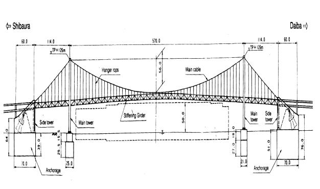
The Rainbow Bridge has become a new landmark in the Port of Tokyo. The bridge provides direct access between central Tokyo and a waterfront development now under construction. It also connects two expressways on both sides of the Port, creating the first express route across the city and is expected to significantly ease traffic congestion in the centre of Tokyo.
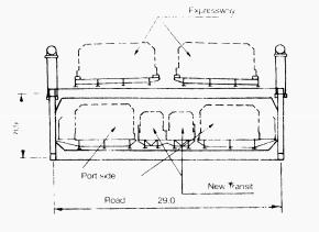
The bridge is a 3-span, 2-hinge stiffening truss suspension type with a centre span of 570 m and a total length of 798 m (Fig. 30). It has a double deck construction: the upper deck carries two two-lane expressways while the lower carries two two-lane roads serving the Port, as well as a railway and footpaths (Fig. 31). The diameter of the main cable is 762 mm.
Fig. 30
The bridge is founded on mudstone (consolidated silt or soft rock) far below the surface. Few suspension bridgeshave their foundations on mudstone and several innovative technologies were employed to overcome this unfavourable condition.
Planning
A suspension-type bridge was selected for the Port of Tokyo crossing to satis-
fy three significant constraints:
-500 m wide ship access with 50 m clearance
-main tower height, including erection equipment, of less than 155 m due to the proximity (9 km) of Haneda International Airport.
-limited length for the side spans to link up with existing expressways on both sides of the bridge.
A cable-stayed bridge could have been considered for the 570 m span, howev-
189
er the height of the towers for this type |
The anchorage caissons are 70 m X 45 |
||
of design would have been about 200 |
m. One anchorage caisson v as con- |
||
m. Besides, a cable-stayed design |
structed at sea using a steel box cais- |
||
would have suffered excessive nega- |
son prefabricated in a shipyard; the |
||
tive reaction (uplift) at the link shoe of |
other was constructed on land. |
||
the side spans. For these reasons and |
For the pneumatic caissons, robotic ex- |
||
economic considerations, a suspen- |
cavation was employed. A computer- |
||
sion-type bridge was determined to be |
controlled caisson shovel was operated |
||
the best choice. |
|
remotely using a video camera. Exca- |
|
|
|
vated materials were placed onto an |
|
|
|
automatic belt conveyer for removal. |
|
|
|
This method ensured worker safety |
|
|
|
and construction efficiency under the |
|
|
|
high atmospheric pressure (3.5 bar) in |
|
|
|
the caisson's chamber. In addition, |
|
|
|
special digging machines were used |
|
|
|
for the excavation of the hard mud- |
|
|
|
stone. |
|
|
|
Since an anchorage would be subjected |
|
Fig. 31 |
to a huge eccentric force due to the ca- |
||
Substructure |
|
ble tension (230 MN) a precise pre- |
|
|
|
diction of long-term (100 years') de- |
|
The water depth at the site is approxi- |
formation of the mudstone bearing |
||
mately 12 m, and the subsurface |
layer was essential) The initial predic- |
||
ground consists of a weak alluvial clay |
tion was modified repeatedly using a |
||
layer on top of a mudstone stratum. |
measured displacement at each con- |
||
The mudstone bearing layer was found |
struction stage, and the values obtained |
||
at levels between -30 and -38 m. |
were considered in the design of the |
||
Pneumatic caisson |
foundations were |
superstructure. |
|
designed and constructed for the two |
|
|
|
main towers and the two anchorages. |
|
|
|
|
|
|
|
Item |
Content |
|
|
|
|
|
|
Type of bridge |
3-span, 2 hinged-stiffening truss, doubledeck suspension |
||
girder |
|
|
|
Span layout |
Stiffening truss: 107.5 + 562.0 + 107.5 m |
|
|
|
Cable: 147.5 + 570.0 + 147.0 m |
|
|
Tower works |
|
|
|
Structural type: |
Longitudinal direction: flexible hinge at top of tower |
|
|
|
Transverse: 3-story frame rigid (1 story above road) |
|
|
|
|
|
|
190

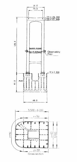
Tower height: |
121.866 m (cable theoretical top: 126.0 m) |
|
|
Height of tower |
P36 |
(Shibaura Main Tower): 2.866 m |
|
foundation: |
P37 |
(Daiba Main Tower): 4.5 m |
|
Centre distance |
P36 |
(Shibaura Main Tower) at foundation: |
30.862 m |
between towers: |
|
at tower top: |
30.084 m |
|
P37 |
(Daiba Main Tower) at foundation: |
30.851 m |
|
|
at tower top: |
30.084 m |
Cable works |
|
Cable type: |
PWS (parallel wire strand) |
Structure |
Main span sag: /= 57.6 m; sag ratio: n = 1/9.9 |
dimensions: |
Centre distance between cables: 29.0 m |
Cable diameters: |
Main span: 762 mm; 127 strands per cable |
|
Side span: 771 mm; 130 strands per cable |
Strand: |
Diagonal; 69.8 mm 0 |
Wire: |
5.37 mm 0; tensile strength: 160-180 kg/mm2 |
Hanger rope: |
Centre Fit Rope Core (CFRC); 4 ropes/panel point |
|
|
Stiffening girder works |
|
Structural type: |
Main structure: parallel chord Warren truss |
|
Lateral bracing: K-truss |
Hanging type: |
Anchoring to upper chord |
Structure |
Main structure height: 8.9 m |
dimensions: |
Main structure width: width: 29.0 m |
Upper floor |
Expressway (multi-span continuous steel deck |
system: |
girder, effective width: 9.25 m) Note: Main span is |
|
of 56 span continuous structure, rigidly connected at |
|
both ends |
Lower floor |
Port roadway (multi-span continuous steel deck |
system: |
girder, effective width: 7.5 m, including walkway |
|
1.5-2.5 m wide) |
|
Rail transportation system (multi-span continuous |
|
steel deck girder, RC track gauge: 1.7 m) |
Table 3: Basic structural specifications
The concrete volume of each anchor- |
the sand and -27 to 15 °C for the grav- |
age, including the top slab of the cais- |
el. Finally, preset water pipes further |
son, amounted to 60000 m3. In order to |
helped to cool the mix after placement. |
reduce cracking caused by the heat of |
Superstructure |
hydration, an ultra-low-heat cement |
|
was used. In addition, liquid nitrogen |
|
was sprayed onto the aggregate, result- |
The steel weights for the superstruc- |
ing in temperatures of about 3°C for |
ture included 14100 t for the towers; |
191
83001 for the cables, 23 7001 for the stiffening girders. The basic specifications for the tower, cable and stiffening girder works are shown in Table 3.
tion due to wind forces. Based on wind tunnel tests, damping devices including an active mass damper, were installed at the tower tops to resist possible vortex-excited vibration.
A main cable consists of 130 strands (each composed of 127 wires) in the side spans and 127 strands in the centre span. Since the short side spans of the Rainbow Bridge might have encountered a problem due to unbalanced tensile forces in the main cables on each side of two towers, three additional cable strands were installed in the side spans to balance the stress level in the main cable. In addition, a "horizontal frictional board" with an increased surface friction coefficient was fitted to the towers' top cable saddles to further resist cable slippage due to any unbalanced tension. After erection of the strands, the cable was shaped using a squeezing machine.
The Rainbow Bridge also features a multi-continuous (56-span continuous) steel deck floor system with improved shoes on its upper deck. There are no expansion joints in the centre span of the expressway, resulting in a comfortable driving surface and reduced maintenance requirements.
Aesthetics
Fig. 32
The main towers (Fig. 32) are made of hollow steel box section and were each assembled in three large blocks using 33001 and 41001 (hanging weight) floating cranes. Until erection of the main cables, free-standing towers of suspension bridges experience vibra-
From the outset, the owner was very conscious of the environmental and visual impact of the bridge, given its prominent location in the Port of Tokyo. A Committee on Aesthetics was established and much attention was paid to architectural and structural de-
192