

2376
.pdfFig. 18
The first components to be built of synthetic materials will be long stabilizing cables. For these cables, the ideal axial stiffness, which is a function of sag, is extremely important [6]. For long spans, lighter carbon fiber cables can achieve the same stiffness with a much smaller cross section than heavier steel cables.
As spans increase, it will become necessary to use synthetic materials for the main suspension cables. Already for 3000 m spans, the weight per unit length of suspension cables is roughly equal to that of the girder it supports. The unit weight of the cables should not increase as spans are increased even further. This can be avoided most simply through the use of a hybrid cable system, in which cables are composed of synthetics and steel acting together. Although the coefficients of thermal expansion are different for these two materials, the stresses redistributed from one material to the other
due to change in temperature are small compared to stresses due to load.
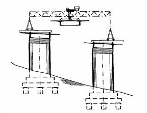
The last step in the development of bridges of extremely long spans may be not only the entire cable system of synthetic materials, but also the girder. The first tests of girders made of synthetics are already under way [7]. The proposed basic structural concept for the design and construction of the towers would remain valid in such a case.
Concluding Remarks
Simple extrapolations of rather conventional concepts usually do not lead to great progress in technological development. This is true as well for extremely long spans in bridge structures. Because today lightweight high strength materials are not yet inexpensive and cannot yet be produced in sufficient quantity, economical and practical designs for extremely long spans require unconventional structural sys-
163
tems. The proposed structural concept, |
[3] CASTELLANI, A. The Project for |
with its relatively simple construction |
the Bridge over the Messina Strait, |
technique, is certainly suited for this |
ibid., pp. 517-527. |
design problem. It is suitable, not only |
[4] WALTHER, R., AMSLER, D. Hy- |
for great spans but also for narrow |
brid Suspension Systems for Very Long |
bridges with shorter spans and espe- |
Span Bridges: Aerodynamic Analysis |
cially also for long span pipeline |
and Cost Estimates, ibid., pp. 529-536. |
bridges. |
[5] GIMSING, N.J. Suspended Bridges |
References |
with Very Long Spans, ibid., pp. 489- |
504. |
|
[1] LEONHARDT, F. Zur Entwicklung |
[6] MEIER, U. Carbon Fiber- |
aerodynamisch stabiler Hangebrii- |
Reinforced Polymers: Modern Materi- |
cken. Die Bautechnik 45, Heft 10 und |
als in Bridge Engineering. IABSE, Zu- |
11,1968. |
rich, SEI1/1992, p. 7. |
[2] LACROIX, R., et al. 3000 Metres: |
(7) SEIBLE, E, BURGUENO, R. Ad- |
We Can Make It! Proc. Int. Conf. |
vanced Composites in Cable Stayed |
IABSE-FIP, Deauville, 1994, Vol. 1, |
Bridges. Seminar in Cable-Stayed |
pp. 505-515. |
Bridges, Miami, FL, Oct. 17-18,1994. |
WEST SEATTLE SWING BRIDGE, SEATTLE, WASHINGTON
John H. Clark, Vice Pres.,
Andersen Bjornstad Kane Jacobs, Inc.,
Seattle, WA
Planning
A double-leaf concrete swing bridge across the Duwamish River in Seattle, Washington, represents a revival of a type of movable bridge long out of favor and incorporates new concepts in machinery and movable bridge technology. The bridge connects two portions of the industrial port area of Seattle across one of its major shipping channels.
Prospects for widening the current-46 m wide ship channel to 76 m required replacement of an existing bascule, built in 1927. Navigation traffic in 1994 required approximately 10 open-
ings per day of the existing bridge, which provides 14 m of vertical clearance over high water. Increasing the vertical clearance from 14 m for the existing bascule bridge to 17 m for the new bridge was predicted to be sufficient to reduce the number of openings to 7 per day average, primarily for large ocean-going barges and ships. Roadway traffic is predicted to reach 11000 vehicles per day, with approximately 15 % truck traffic.
Pedestrians and bicycles are also provided for on the new swing span, but are excluded from the high level bridge. The total structure width of 15.2 m provides for two traffic lanes and one combined bicycle/pedestrian way 3.66 m wide.
164
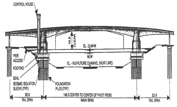
Fig. 19
The swing bridge alignment was |
the alignment was chosen, the span |
placed on the existing bridge align- |
lengths were fixed. The west approach |
ment to minimize required right of way |
length of 153 m is determined by the |
and revisions to the existing street |
need to cross over a railroad track and |
network. This alignment results in the |
an intersecting street. The east ap- |
bridge axis being skewed approxi- |
proach length of 147 m was deter- |
mately 45° to the channel. A total of |
mined by the maximum grade of 7% |
nineteen different alignments and three |
and vertical curve lengths required for |
basic structure types were evaluated |
proper sight distance. Stair towers for |
before selection of the swing bridge for |
pedestrian access are provided on each |
final design development. Other struc- |
approach. A control tower for the |
ture types investigated in the prelimi- |
bridge operator is adjacent to, but sep- |
nary design stages were a vertical lift |
arate from, the west pivot pier. The |
bridge and a bascule bridge. |
control tower is a 36 m high structure, |
The 146 m span center-to-center of |
so that the bridge operator has unre- |
pivot piers (Fig. 19) for the swing |
stricted view of the channel and all of, |
bridge was established by the width of |
the approach roadway. |
the open west leaf and the location of a |
Structural Design |
column of the adjacent high level |
|
bridge. The east pivot pier is then |
|
placed symmetrically about the center- |
The crossing site is near the mouth of |
line of the proposed channel. The tail |
the Duwamish River. Soils encoun- |
span length of 53 m was also set by the |
tered at the site range from hydraulic |
column of the high level bridge. Once |
fill and recent alluvial sands and silts |
165
to heavily pre-consolidated glacial till. |
transverse stiffness of the piles which |
|||
Depth to the till varies from 15 m on |
would have led to eccentricity between |
|||
the west end of the project to 60 m on |
the center of mass and center of rigid- |
|||
the east end. Lenses of loose silt exist |
ity. These two problems were ad- |
|||
erratically throughout |
the alluvium |
dressed by the new concept of "seismic |
||
layer. The loose surficial silts and hy- |
isolation" sleeves. |
|
||
draulic fill are deemed susceptible to |
Considerations in the choice for the |
|||
liquefaction in major seismic events. |
superstructure design were construc- |
|||
Densification by vibro-flotation was |
tion economy, maintenance costs, traf- |
|||
specified to prevent such liquefaction. |
fic safety and aesthetic compatibility |
|||
Seismicity in the area is moderately ac- |
with the adjacent high-level bridge (a |
|||
tive. Seismic design criteria generally |
concrete box girder). Two designs |
|||
followed the Guide Specifications for |
were prepared and advertised for bids, |
|||
Seismic Design of Highway Bridges, |
a post-tensioned segmental concrete |
|||
1983, of the American Association of |
box girder and a steel box girder with a |
|||
State Highway and Transportation Of- |
precast prestressed concrete deck made |
|||
ficials, with appropriate |
modifications |
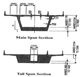
composite after erection. Typical cross |
||
for the unique structure. The basic |
sections of the concrete alternative are |
|||
seismic coefficient, amax is 0.30 g and |
shown in (Fig. 20). |
|
||
the soil type is Type III. |
|
A major challenge in the design of the |
||
The main piers and superstructure |
concrete box girder bridge was control |
|||
comprise a structural unit which does |
of long-term deformations. Provisions |
|||
not contain the "ductile element" upon |
for control of both long-term and |
|||
which the Guide Specifications are |
short-term deformations included ad- |
|||
|
|
ditional post-tensioning beyond that |
||
|
|
required for stress control, provision of |
||
|
|
some unbonded tendons, provision for |
||
|
|
additional future tendons, |
provisions |
|
|
|
for adjustment of approach span eleva- |
||
|
|
tion at the tail span joint, provision for |
||
|
|
vertical adjustment of each leaf as a |
||
|
|
whole, |
and specifications |
requiring |
|
|
nearly |
simultaneous construction of |
|
|
|
the two movable leaves. |
|
|
|
|
The first line of defense against un- |
||
|
|
wanted long-term deformation was the |
||
|
|
adoption of the principle of load bal- |
||
|
|
ancing for the design of the longitudi- |
||
Fig. 20 |
|
nal post-tensioning. The amount of |
||
based. The location of the piers in the |
prestress provided is the amount re- |
|||
sloping bank of the existing and future |
quired to provide 100% load balancing |
|||
channel created a problem of differing |
for the final dead load condition. This |
|||
166
required approximately 30% more post-tensioning than the amount re quired to satisfy service load stress conditions. The deck of the box girder is post-tensioned transversely and vertical post-tensioning is included in the webs. The additional longitudinal posttensioning reduced the need for vertical post-tensioning in some areas.
Static balance of each leaf about the pivot pier is achieved by thickening the webs and bottom slab in the tail span and by the addition of ballast concrete and galvanized reinforcing steel bars such that the last 12 m of the tail span is solid except for an access shaft. Asbuilt measurements were taken after
casting of each section so that the final static balance could be closely predicted. It was found necessary to explicitly account for the measured density of the concrete (from quality control test cylinders) and the actual weight of reinforcing and prestressing steel in each segment to accurately predict the static balance. Allowable static imbalance during construction while the bridge rested on temporary service bearings was 72 MNm. Static imbalance during service operations of the movable leaves was limited to 6.8 MNm to avoid stick-slip chatter in the pivot shaft guide bearings.
Fig. 21
167
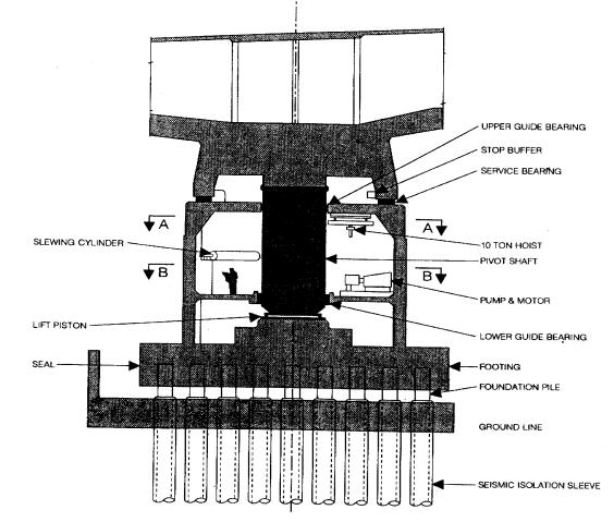
Pier House and Machinery
The 12.8 m diameter pier house carries the superstructure loads to the foundations and houses the drive machinery, emergency generators, and part of the control system. The pier table element of each leaf is supported by a transition element which provides two load paths to the foundation. The closed position path (serving vehicular traffic) is from the superstructure pier table through a conical shell to the walls of the pier house. Service bearings made up from steel plates with reinforced elastomers separate the transition element from the roof of the pier house. These service bearings are placed on an 11.4 m diameter circle. Temporary bearings were placed between the permanent service bearings to provide stability during construction of the cast-in-place segmental concrete leaves.
The operating position load path is from the pier table through the center portion of the transition element to the 3.66 m diameter pivot shaft. The pivot shaft is a concrete-filled steel shell 44 mm thick which in turn rests on the hydraulically operated lift-turn cylinder. The pivot shaft is maintained in the vertical position by guide bearings (Fig. 21) at the roof and operating floor level of the pier house. In the operating position, the whole movable leaf including transition element and pivot shaft are raised approximately 25 mm to transfer the load from the service bearings to the pivot shaft. A reinforced concrete footing founded on 36
concrete filled steel pipe piles, 91 cm diameter, completes both load paths. Heavy locks at the tail span joint and at the center joint are provided for transfer of seismic response loads and to restrain differential displacements due traffic, differential temperature, and accidental misalignment. The torsional stiffness of the box section is sufficiently high that locks were provided only on the longitudinal centerline of the section. The locks are driven by hydraulic rams powered by local pumps.
Twin hydraulic slewing cylinders (56 cm bore x 234 cm stroke) rotate each movable leaf from the closed position to the open position to allow for passage of ships. The operational cycle is based on a normal two minute slewing time, total cycle including traffic lights and gates is approximately 4.5 minutes. Friction is minimized due to the fact that the structure is supported on the hydraulic fluid of the lift-turn cylinder. The principal source of friction is the pivot shaft guide bearings which maintain vertical alignment.
Power for raising and rotating the movable leaf is provided by 3-75 kW, 8-liter-per-second hydraulic pumps in each pier house. Normal operation is with two pumps, the third pump alternates as a spare. Other redundancies built into the system include the ability to slew the bridge using only one slewing cylinder (with increased cycle time) and even to slew the bridge against the friction of the service bearings, should the lift/turn cylinder fail to operate.
168

Hydraulic system components are designed to operate at a normal pressure of 11.7 MPa and an emergency (slewing against the service bearing friction) pressure of 41.4 Mpa.
The control unit is a programmable controller which sequences operations, and provides status information to the bridge operator. The primary position control is limit switches which initiate braking via the controller. The control system is essentially the same as manual operation except that the controller "pushes the buttons," checks interlocks, and announces the status on a monitor. Manual override is possible for most steps of the operation.
Diesel powered emergency generator sets (350 kW) are provided in each pier house on the lower floor. Fuel storage is placed in day tanks on the shore.
Construction Costs
Bids for the construction of the project were received in September 1988. Five bids were received for the concrete box girder alternative ranging from USD 33.5 to USD 37.6 million, including demolition of the south bascule, all approach work and site work. The cost breakdown for major work categories (based on the low bid) is presented in Table 1. The contract called for a 22 month construction schedule.
Item |
Cost |
|
USD |
|
Millions |
Mobilization |
2. 80 |
Demolition |
3.76 |
Civil: streets, utilities, |
3.38 |
traffic |
|
Approach spans |
4.66 |
Swing piers |
6.87 |
Swing spans |
5.60 |
Machinery |
3.98 |
Electrical |
1.06 |
Controls, control tower |
0.94 |
Pier protection |
0.48 |
Total |
33.53 |
Table 1: Cost breakdown (low bid)
Owner: City of Seattle, WA
Design:
Andersen Bjornstad Kane Jacobs,
Seattle, WA
Parson Brinckerhoff Quade and
Douglas, Seattle, WA
Tudor Engineering, Seattle, WA
Contractor:
Kiewit-Global Joint Venture,
Seattle, WA
Service date August 1992
PRECAST SEGMENTAL HIGHWAY VIADUCTS, HAWAII
Gerard Sauvageot, Vice Pres. |
Oahu Island, in the Hawaiian Islands, |
|
J. Muller International, San Diego, CA |
with the state capital Honolulu and the |
|
General Description |
bay of Pearl Harbor, is presently expe- |
|
riencing significant new urban arid |
||
|
169
tourism development. To link the most populated areas of the south to the towns and military bases on the northeast, the Hawaiian Department of Transportation, with the financial support of the US Federal Highway Administration, is building an extension of the H-3 Freeway across the steep and volcanic Koolau Mountains. Because of its natural beauty and archaeological significance, the whole area is very sensitive environmentally. From the vicinity of Pearl Harbor, the freeway includes the North Halawa Viaducts, the Haiku Tunnels under the mountain range, and the Windward Viaducts on the north slope, where it will connect to the north end of H-3 already in service
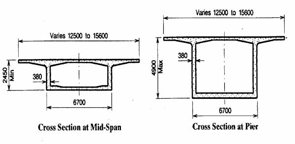
The new Windward Viaducts consist of twin parallel prestressed concrete structures approximately 2 km long with 24 spans each. The maximum span length is 91.5 m and column height varies from 3.6 to 48.8 m. The width of each bridge varies from 12.8 to 17.4 m. The geometry of the viaducts includes reverse curves with radius varying between 470 and 753 m and cross slope between 5.5 % on one side and 6.8% on the other side. The longitudinal slope of the structure is about 5 %. The horizontal distance between the structures is constant on most of the length at 21.3 m, but increases at one end where it connects to the two separate tunnels. Crosswise the elevation of the two parallel decks varies by as much as 4.6 m.
Value Engineering Design
The structure was designed as a vari-
able depth concrete box girder to be built in balanced cantilever with 4.9 m long superstructure segments cast in place with travelling forms. The structure shown in the base design would have been supported by cast-in-place hollow concrete piers with a single row of fixed or sliding bearings at the top. The foundations consisted of 400 mm diameter, octagonal precast driven piles.
After bidding on the base design, an alternate was proposed according to "Value Engineering" procedure, whereby certain economic and technical conditions must be met, such as sharing any savings with the owner and retaining the appearance, geometry, and alignment of the structure, which had been the object of a lengthy environmental impact assessment.
The alternate design accepted by the contractors’ joint venture and the owner, included the following changes:
-piers and superstructure were made monolithic
-precast piles were replaced with 1.5 m diameter drilled shafts
-precast segmental construction was used for the superstructure.
The project specifications allowed 1360 days for the construction of the viaducts. This schedule did not provide additional time for rainy days, which are frequent on the windward side of the island. Precast construction has the advantage of decreasing the amount of work performed at the site, improving quality and speed of erection and significantly, allowing the superstructure
170
to be entirely constructed from above |
expansion joint is located every four |
in this difficult terrain. |
spans, at about one-quarter of the span. |
Each viaduct is a single box made of |
This disposition reduces deflections |
precast segments with vertical webs |
and changes of angle at the joint. The |
and parabolic intrados. The depth var- |
two hinge segments are temporarily |
ies from 4.9 m at pier to 2.45 m at |
prestressed and treated as one piece |
midspan (Fig. 22). The length of the |
during the erection process. Tendons |
precast segments are such that the |
through the hinge are released after the |
maximum weight is 70 t. A 2-segment |
next span is installed and stressed. |
Fig. 22
The longitudinal post'-tensioning lay- |
plied to the bridge at the end of con- |
out was conventional with straight 19 x |
struction according to the original pro- |
13 mm strand tendons placed within |
ject specifications. |
the top slab and anchored at the seg- |
Erection System |
ment joints, close to the top of the |
|
webs, 32 tendons were used in each |
|
typical cantilever. The continuity post- |
A special erection system was de- |
tensioning consists typically of 18-19 x |
signed and used for this structure with |
13 mm strand tendons placed in the |
a self-launching gantry that allowed |
bottom slab and anchored in concrete |
both viaduct structures to be built si- |
blocks. No draped tendons were re- |
multaneously. The system is designed |
quired in the webs, except for the |
to accommodate variable cross slopes, |
hinge and abutment spans. Additional |
curves, differential elevations, and |
deviation blocks running from pier |
variable distances between the two |
segment diaphragm to pier segment |
structures. |
diaphragm provide for any future ex- |
The system includes two independent |
ternal post-tensioning contingencies. A |
erection trusses, steel support beams |
75 mm thick reinforced overlay is ap- |
supporting the trusses, a gantry crane |
171
and lifting trolley. The gantry crane is |
26.2 m away) is entirely controlled by |
supported by two trusses, one on each |
an electronic device monitoring the |
bridge. |
speed of the hydraulic motors and |
Transverse cross beams act as supports |
keeping the "lag" within acceptable |
for the trusses. Each truss rests on |
tolerances. |
three cross beams, one at the rear, at |
The launching of the trusses to the next |
the tip of the previous cantilever, one |
pier is done by fixing the gantry crane |
on top of the pier segment of the can- |
to the concrete deck through a tempo- |
tilever under construction and a third, |
rary attachment and activating its hy- |
mobile, on the front arm of the con- |
draulic motors which then push the |
crete cantilever and supporting the |
trusses under the gantry instead of |
truss as the construction progresses, |
moving the gantry on the trusses. The |
reducing deflections and moments in |
trusses are launched one at a time to |
the truss. This was possible because of |
minimize the load on the cantilever. |
the moment-resisting connection be- |
A complete launching from pier to pier |
tween the deck and pier shaft. Each |
took about 18 hours (Fig. 23). After |
cross beam is set horizontally on the |
completion of the learning curve, the |
concrete deck. |
contractor typically achieved the re- |
A gantry crane rolls longitudinally on |
sults shown in Table 2. On the best |
the top members of the two trusses. |
day, the contractor was able to set 16 |
The gantry crane carries a lifting trol- |
segments. |
ley running transversely to the two |
|
trusses. The segments are delivered by |
|
truck at the extremity of the previous |
|
cantilever, picked up by the gantry |
|
crane/lifting trolley and delivered at |
|
either ends of the twin cantilevers un- |
|
der construction. The gantry crane is |
|
equipped with two legs on wheels. The |
|
leg on the mountainside truss is the |
|
"fixed leg." The leg on the ocean side |
|
truss is the pendulum leg. Each leg is |
Fig. 23 |
built with the minimum degree of free- |
|
dom compatible with its motion and |
The remarkable speed that this erection |
the stability of the gantry crane. The |
system is able to achieve is due to its |
longitudinal displacement on top of the |
separation of the two operations which |
trusses is by a rack-and-pinion hydrau- |
were performed for each pair of seg- |
lically driven system insuring total |
ments, i.e., placing and post-ten- |
safety on the 5 % longitudinal slope of |
sioning. During the operation of plac- |
the bridge. The relative longitudinal |
ing a pair of segments, which included |
motion of one leg with regard to the |
bringing the segments to the erection |
other (each leg running on one truss |
equipment, applying epoxy and tem- |
172