

ТЕКСТЫ ДЛЯ ДОПОЛНИТЕЛЬНОГО ЧТЕНИЯ, ПЕРЕВОДА И РЕФЕРИРОВАНИЯ
ADJUSTABLE SPEED DRIVE SYSTEMS
СMany applications have unique demands and characteristics. Drive vendors have responded to this demand by producing a variety of
Commercial and industrial firms today use adjustable-speed drive (ASD) systems for a variety of applications. Most common of these include standard pumps, fans, and blowers. Newer applications include hoists and cranes, conveyors, machine tools, film lines, extruders, and tex-
иNew generation ASDs have evolved with advancements in solidstate electronics. ASDs can now be applied to ac motors regardless of motor horsepower or location within a facility and can be used to drive almost all types of motorized equipment, from a small fan to the largest extruder or machine tool. Commercial and industrial facilities can expect to dramatically reduce both energy consumption and operating and maintenance costs while offering improved operating conditions by using new genera-
tile-fiber spinning machines.
drives. The combination of the many types of drives available and the abundance of applications has made the selection of the optimum drive for a given application a challenge.
tion electronicбАASDs. The latest generation of ASDs allows ac induction motors to be just as controllable and efficient as their dc counterparts were. Historically a variety of terms have been used to describe a system that permits a mechanical load to be driven at user-selected speeds. These terms
include, but are not limited to: |
И |
Variable-Spee Drive Variable-Frequency Drive Adjustable- |
|
Frequency Drive Adjustable-SpeedДDrive |
|
The term variable implies a change that may or may not be under the |
|
control of the user. Adjustable is the preferred term since this refers to a |
|
change directly under control of the user. The term frequency can only be |
|
applied to drives with an ac output, while the term speed is preferred since this includes both ac and dc drives. Thus, the term most commonly accepted is Adjustable-Speed Drive (ASD).
BASIC ASD COMPONENTS
Most ASD units consist of three basic parts. A rectifier that converts the fixed frequency ac input voltage to dc. An inverter that switches the
74
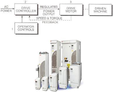
rectified dc voltage to an adjustable frequency ac output voltage. (The inverter may also control output current flow, if desired.) The dc link connects the rectifier to the inverter. A set of controls directs the rectifier and inverter to produce the desired ac frequency and voltage to meet the needs of the ASD system at any moment in time.
СThe advantages of ASDs do not stop with saving energy and improving control. ASD technology can now be applied to manufacturing equipment previously considered too expensive or uneconomical. Such applications are often unique to a particular industry and its equipment, or even to aиparticular facility. Cost benefits, such as those obtained from improved quality, may be desirable for each application.
бА
РисД. 15
TRANSFORMERSИ
It is undoubtedly true that the principle of transformer action and the practical application of this principle in connection with the construction of transformers and induction-type motors are responsible for the widespread use of alternating current as a primary source of electrical energy. The transformer is a simple, efficient, and comparatively inexpensive device used primarily in a-c circuits for the purpose of changing the voltage from one value to another. There are no moving parts in the transformer, which means that mechanical losses, always present and responsible for much of the heating of rotating and reciprocating machines, are entirely absent. Actually, a transformer is a device that transfers electrical energy from one electric circuit to anoth-
75
er without a change of frequency. This energy transfer usually takes place with a voltage change, although the latter is not always necessary or even desirable. The electric circuits being insulated from each other, as they are in most transformers, they are conventional and are generally referred to as transformers. In some special cases, the electric circuits
Сare joined together, in which case the device is referred to as an autotransformer. The electric transformer winding being connected to the source of supply is called the primary, the winding that feeds the load being known as the secondary. Some transformers are designed to raise theиprimary voltage to a higher value, in which case they are known as step-up transformers; others are constructed to reduce the primary voltage to a lower value, in which case they are called step-down transformers. In step-up transformers the current on the secondary side is lowered in бАthe same ratio as the voltage is raised, in step-down transformers the current on the secondary side being raised in the same ratio as the voltage is lowered. Transformers have many applications in a-c circuits that require both the raising and lowering of the primary voltage as well as the lowering and raising of the primary current. When used in groups in poly phase circuits, they are especially valuable in performing many im portant functions, one of which, apart from its volt- age-changing use, is to change the number of phases from two to three, three to two, three to six, or several other combinations.
TYPES AND CHARACTERISTICSДOF
ALTERNATING CURRENT MOTORS
Only three general types of d-c motor are found in practice, a comparatively large number of different constructions being available for use in a-c systems. The reasons for this situationИis that each type of a-c motor is confined to narrower operating characteristics, especially with regard to such important matters as torque, overload capacity, speed variation, speed control, and starting procedures. Furthermore, a-c motors must be constructed for operation on single-phase service or polyphase (either twoor three-phase) service; in one type of construction they must perform satisfactorily on d-c service as well as on singlephase alternating current.
Classification of Single-Phase Motors. Single-phase motors generally have low horsepower ratings and are used to operate mechanical devices and machines requiring a comparatively small amount of power. Their greatest fields of application are in the fractional-horsepower
76
range, that is, below 1 hp. Motors larger than the latter, up to perhaps 10 hp, are sometimes used on farms and in small shops and factories where polyphase power is not available. Polyphase motors generally have better operating characteristics than single-phase machines and cost less per horsepower, so that it is usually true that single-phase mo-
Сtors are used in the larger sizes only because of twoor three-phase service not being available.
In the single-phase classification may be listed the following types of motors: shaded-pole, reluctance, split-phase (with or without capacitorиstarting), repulsion, repulsion-start, repulsion-induction, series (a-c only or universal), and synchronous.
Shaded-pole and reluctance motors are built in very small sizes from about 1/500 to 1/6 hp; they are cheap to construct, have low starting torque,бАlittle overload capacity, and low efficiency and may be speed-controlled.
Standard split-phase motors are manufactured in sizes up to 3/4 hp; they are comparatively low in cost, have fair starting torque, not much overload capacity, and fair efficiency, and operate at nearly constant speed. Split-phase motors equipped with capacitors have high starting torque and may or may not be arranged to continue to run with a capacitor. Their capacitor being used only during the starting period, they are called capacitor-start split-phase motors; two values of capacitor being provided, one for startingДand another for running, they are referred to as two-value capacitor motors. However, whether or not these motors are provided with capacitors, they are all, nevertheless, split-phase motors.
Series motors are usually constructed for service on direct or alternating current up to 60 cycles, in which caseИthey are called universal motors. When properly designed, they will operate with complete satisfaction on direct or alternating current, developing high starting torque, having excellent overload capacity and good efficiency, and permitting the speed to be controlled over very wide limits. Such motors are not as trouble-free as those described above (shaded-pole, reluctance, and split-phase types), because they have the usual commutator and brushes and their, accompanying commutation problems.
Synchronous motors, as the name implies, operate at synchronous speed, that is, a definite, constant speed determined only by the frequency of the supply and the number of poles on the machine. They have very little starting torque, practically no overload capacity, and are quite in-
77
efficient; they have, however, the one important characteristic possessed by none of the motors previously discussed, that is, absolute constancy of speed, a requirement that is very important for timing devices.
Classification of Polyphase Motors. Polyphase motors, that is, machines served with twoor three-phase power, may be classified as Сfollows: induction (squirrel-cage or wound-rotor types), commutator, or
synchronous.
Squirrel-cage induction motors are widely used because of their having, generally speaking, desirable all-purpose characteristics. They are comparatively low in cost per horsepower, have good starting torque and overload capacity, are highly efficient, and are particularly rugged and trouble-free. These motors will operate in an atmosphere containing dirt, moisture, or corrosive or explosive fumes and can even
и be constructedбАto perform submerged in oil or water. They are, practi-
cally speaking, constant-speed motors in the sense that change in load does not affect the speed by more than about 5 per cent. Such motors are, however, of a disadvantage when it becomes necessary to control the speed, because it is usually difficult or expensive, from the standpoint of additional equipment, to do so. When speed control becomes a necessary requirement of an application, the squirrel-cage rotor is often replaced by a wound rotor, its winding ends being connected to slip rings. Speed control is then accomplished by connecting a resistor con-
considerably more starting torque.ДIt does, however, have a lower fullload efficiency and a greater speed variation with load changes than does the squirrel-cage type of motor.
troller to the brushes riding on the slip rings; the greater the resistance inserted, the lower the speed, and vice versa. Wound-rotor motors, therefore, differ from squirrel-cage motors only by the construction of
the rotor, the stator of both types being exactly similar. In addition to its
speed-control feature, the wound-rotor induction motor also develops И
Synchronous motors for polyphase service are generally constructed with a stator core and winding similar to those used on in-
duction motors (squirrel-cage or wound-rotor), but with a rotor consisting of a set of salient poles. The latter must be excited with direct current from a small exciter, that is, a self-excited shunt generator, mounted on an extension of the motor shaft or coming from a separate d-c source. Direct current is fed to the rotor field through brushes and slip rings. Since synchronous motors, as such, have no starting torque, it is always necessary to provide the rotor poles with a
78
complete squirrel cage built into the pole faces. The motor can then be started in much the same way as are squirrel-cage induction machines; when nearly synchronous speed is reached, the d-c rotor field is excited, after which the motor continues to run at exactly synchronous speed. The outstanding advantages of this type of motor are (1) absolutely
Сconstant speed, determined only by the frequency of the supply and the number of rotor poles, and (2) the possibility of adjusting the motor power factor to any desirable value. Synchronous motors, when property designed, have good starting torque, overload capacity, and efficiency.иThey are more expensive than induction machines in the smallest sizes, but cost about as much as squirrel-cage or wound-rotor motors in ratings of more than 100 hp. As a rule, synchronous motors are used in applications requiring infrequent starting, where the load is substantially constant,бАand where high power factor or power-factor correction is desirable and profitable.
Although the speed of a wound-rotor motor can be changed over a wide range by the insertion of resistance in the rotor circuit, the efficiency of operation is very low at reduced speed. To offset this disadvantage, particularly in large motors where energy cost is important, special types of machines have been developed. There is a special motor construction that has wide speed-control possibilities In this motor, the stator is of the usual construction found in induction machines, but the rotor differs greatly from any ofДthese already described. The latter has two windings, one on the top of the other, placed in deep slots. The primary winding, in the bottom of the slots, is connected to slip rings and is fed, through brushes, with polyphase alternating current. The other winding, on top of the primary and next to the rotor surface, is connected to a commutator. Finally, the statorИwinding, called the secondary, is connected to brushes riding on the commutator. Speed control is accomplished by shifting the brushes over the commutator, the method used to be an ingenious mechanical lever construction permitting the motion of all brushes simultaneously by the manual or motorcontrolled operation of a handle. Such motors are high in cost per horsepower but have good efficiency, starting torque, and overload capacity. They are used only when it is extremely important that the speed be varied over a wide range. An additional advantage of this motor is that power-factor adjustment is also possible.
79
AC INDUCTION MOTORS
AC induction motors are ideal for most industrial and commercial applications because of their simple construction and low number of parts, which reduce maintenance cost. Induction motors are frequently used for both constant-speed and adjustable speed drive (ASD) applications.
СThe two basic parts of an induction motor are the stationary stator located in the motor frame and the rotor that is free to rotate with the motor shaft. Today's motor design and construction are highly refined. For example, stator and rotor laminations have been designed to achieve maximum magneticиdensity with minimum core losses and heating. The basic simplicity of this design ensures high efficiency and makes them easily adaptable to a variety of shapes and enclosures.
A three-phase induction motor can best be understood by examining the three-phaseбАvoltage source that powers the motor. Three-phase currents flowing in the motor leads establish a rotating magnetic field in the stator coils. This magnetic field continuously pulsates across the air gap and into the rotor. As magnetic flux cuts across the rotor bars, a voltage is induced in them, much as a voltage is induced in the secondary winding of a transformer. Because the rotor bars are part of a closed circuit (including the end rings), a current begins to circulate in them. The rotor current in turn produces a magnetic field that interacts with the magnetic field of the stator. Since this field is rotating and magnetically interlocked with the rotor, the rotor is dragged around with theДstator field.
When there is no mechanical load on the motor shaft (no-load condition), the rotor almost manages to keep up with the synchronous speed of the rotating magnetic field in the stator coils. Drag from bearing friction and air resistance prevents perfect synchronicity. As the load increases on the motor shaft, the actual speed of the rotor tendsИto fall further behind the speed of the rotating magnetic field in the stator. This difference in speed causes more magnetic lines to be cut, resulting in more torque being developed in the rotor and delivered to the shaft mechanical load. The rotor always turns at the exact speed necessary to produce the torque required to meet the load placed on the motor shaft at that moment in time. This is usually a dynamic situation, with the motor shaft speed constantly changing slightly to accommodate minor variations in load.
The rotor consists of copper or aluminum bars connected together at the ends with heavy rings. The construction is similar to that of a squirrel cage, a term often used to describe this type of ac induction motor.
80
The rotating magnetic field in the stator coils, in addition to inducing voltages in the rotor bars, also induces voltages in the stator and rotor cores. The voltages in these cores cause small currents, called eddy currents, to flow. The eddy currents serve no useful purpose and result in wasted power. To keep these currents to a minimum, the stator and rotor
Сcores are made of thin steel discs called laminations. These laminations are
coated with insulating varnish and then edge welded together to form a core. This type of core construction substantially reduces eddy current losses, but does not entirely eliminate them.
By varying the design of the basic squirrel-cage motor, almost any characteristic of speed, torque, and voltage can be controlled by the designer. To standardize motor features the National Electrical Manufacturers Association (NEMA) has established standards for a number of motor fea-
tures. |
бА |
||||
|
|
|
|
|
|
The speed of an ac induction motor depends on the frequency of the supply |
|||||
voltageиand the number of poles for which the motor is wound. The term |
|||||
“poles” refers to the manner in which the stator coils are connected to the |
|||||
three incoming power leads to create the desired rotating magnetic field. |
|||||
Motors are always wound with an even number of poles. The higher the |
|||||
input frequency, the faster the motor runs. The more poles a motor has, the |
|||||
slower it runs at a given input frequency. The synchronous speed of an ac |
|||||
induction motor is the speed at which the stator magnetic flux rotates |
|||||
|
|
|
Д |
||
around the stator core at the air gap. At 60 Hz the following synchronous |
|||||
speeds are obtained: |
|
|
|
||
|
|
Number of poles |
RPM |
|
|
|
|
2 |
|
3,600 |
|
|
|
4 |
|
И |
|
|
|
|
1,800 |
|
|
|
|
6 |
|
1,200 |
|
|
|
8 |
|
900 |
|
|
|
10 |
|
720 |
|
|
|
12 |
|
600 |
|
Providing the motor is properly constructed, the output speed can be doubled for a given number of poles by running an ASD supplying the motor at an output frequency of 120 Hz. The actual speed of an induction motor rotor and shaft is always somewhat less than its synchronous speed. The difference between the synchronous and actual speed is called slip. If the rotor rotated as fast as the stator magnetic field, the rotor conductor
81

bars would appear to be standing still with respect to the rotating field. There would be no voltage induced in the rotor bars and no current would be set up to produce torque. Induction motors are made with slip ranging from less than 5% up to 20%. A motor with a slip of 5% or less is known as a normal-slip motor. A normal-slip motor is sometimes referred to as a
С'constant speed' motor because the speed changes very little from no-load to full-load conditions. A common four-pole motor with a synchronous speed of 1,800 rpm may have a no-load speed of 1,795 rpm and a full-load speed of 1,750 rpm. The rate-of-change of slip is approximately linear fromи10% to 110% load, when all other factors such as temperature and voltage are held constant. Motors with slip over 5% are used for hard to start applications.
The direction of rotation of a poly-phase ac induction motor depends on the connectionбАof the stator leads to the power lines. Interchanging any two input leads reverses rotation.
MAGNETIC MOTOR STARTERS
The magnetic motor starter is a magnetic contactor with an overload protection device. Unlike the fuse, the magnetic motor starter does not have to be replaced. It can be reset repeatedly.
Д Рис. 16 И
THE MOTOR CIRCUITS
Larger current-demanding motors use two circuits for operation. One circuit is the three-phase power circuit supplied from the distribution power panel. The other electrical circuit is the control circuit. The figure shows the magnetic motor starter and the power circuit from the distribution power panel. The heavy, dark lines provide the three-phase, high current-carrying power to the motor.
82

СиРис. 17
Inside the magnetic motor starter, directly under the coil, are three large main contact sets. These contacts are in series with the power panel A, B, and C phase terminals and the T1, T2, and T3 motor terminals. As long as these contacts are closed, current from the power distribution panel can operate the motor. This is one circuit.
The other circuit controls the three large contact sets explained |
|
above. The coil in Figure 1 actually moves the contacts. The figure shows |
|
|
Д |
the control circuit that the coil is actually in. M represents the coil in the |
|
figure. |
бА |
The M coil is supplied single-phase power from the magnetic motor start- |
|
ers A and B phase terminals (also known as L1 and L2 terminals). The
figure above shows two M coils: one in its true physical position in the И
magnetic motor starter and the other in the line diagram to explain its function electrically. There is actually only one M coil. The same applies to the NC overload contacts.
When the START button is pressed, a complete circuit from A phase through the M coil, through the NC overload contacts, to the B phase is
completed in the control circuit. The M coil energizes and moves a bar, known as an armature, that is in physical contact with the three large power contacts in the motor's three-phase power circuit. The figure below illustrates this action.
83

С |
|
и |
Рис. 18 |
|
|
The main power circuit contacts for the motor are held open by |
|
spring tension. When the coil becomes energized, the magnetic attraction |
|
between the armature and the magnet overcomes spring tension, and the |
|
main contacts for the motor close. The motor now operates. |
|
When the current to the motor is too great, the overload heaters get |
|
hot. The heatersбАare in series with the motor terminals and the main contacts for the motor. The heaters directly control what happens to the NC overload contacts in the control circuit. When the heaters get hot enough, the overload contacts open, and the M coil de-energizes. The loss of the magnetic field allows spring pressure to open the three main contacts in series with the motor, and the motor stops operating. By de-energizing the one coil (M), all three sets of main contacts open. Detrimental single phas-
ing is avoided. |
Д |
|
|
A minor disadvantage of the thermal overload device is its need to |
|
cool off before being reset. The Figure shows a magnetic motor starter and |
|
the overload heater and NC overload contact section separately. |
|
|
И |
84
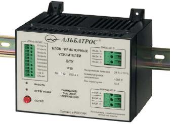
BTU THYRISTOR AMPLIFIER UNIT
С |
|
и |
|
бА |
|
|
Рис. 19 |
1. Purpose
1.1. The BTU thyristor amplifier unit (hereinafter referred to as the "device") built around a solid-state semiconductor optronic three-phase relay is intended for switching of a single– or three-phase voltage applied to an electrical drive of an actuating mechanism. The "Open", "Close" and "Interlock" discrete inputs of the device, which perform control functions, are intended for operation with circuits consisting of "dry contacts" and do not call for additional power sources.ДThe device has a discrete output to indicate current overload in the form of a normally open "dry contact". The device monitors current consumption of the electrical drive across phases B and C. In case of emergency or when the protection circuitry becomes
1.2.1.Nominal values of climatic factors – accordingИto GOST 15150 for the UKhL4 climatic version and atmosphere type II (industrial).
1.2.2.The device protection level is IP20 according to GOST 14254 (protection against getting of foreign solid bodies of more than 12.5 mm in diameter).
2. Specifications
2.1. The device characteristics are as follows:
– the number of discrete inputs to connect external control – three;
85
– the number of discrete outputs to indicate overloads in power circuits of the device – one;
– the number of switched phases – three;
– reversible phases – B and C.
2.2. Arranged on the device front panel are the OPERATION (green- Сcolor) and OVERLOAD (red-color) light-emitting diodes, the RESET button, as well as the CONTROL, 380 V INPUT and 380 V OUTPUT termi-
nal connectors.
2.3. Electrical parameters and characteristics
и2.3.3. Starting time – not more than 10 s.
2.3.1. The device derives the supply from an external DC power
source of (24±0.24) V.
2.3.2. Power consumption of the device via the +24 V circuit is not
more than 180 mA.
2.3.4. As to its level of protection from electric shock, the device belongs to protection class I in compliance with the requirements of GOST 12.2.007.0.
2.3.5. The insulation voltage across the power circuits, control cir-
cuits and the +24 V circuit of the device withstands a test voltage of 1500 VAC 50 Hz without breakdown and surface flashover in normal climatic conditions.
2.3.6. Insulation resistance of the power circuits relative to the con-
trol circuits and the +24 V circuit is not less than 20 megohms in normal climatic conditions.
бА
2.4. The device is rated for continuous operation.
2.5. The parameters of the device discrete inputs are as follows:
Д
–open (closed) contacts of a system connected to the device correspond to the logical zero (unit) at the "Open", "Close" inputs;
–the logicalzero voltage at the "Interlock"input is equal from 0 to 1V;
–the open state of contacts of the system connected to the device corresponds to the logical unit at the "Interlock" input;И
– the minimum duration of the logical unit or zero is equal to 0.1 s;
– the current value in the "Open", "Close" and "Interlock" circuits ranges from 15 to 24 mA.
2.6. The limit parameters of the device keys are as follows:
–a root-mean-square value of the power key switching voltage is not more than 420 V 50 Hz;
–an amplitude value of the power key switching current is not more than 10 A;
86
–the overload key switching voltage is not more than ±36 V;
–the overload key switching current is not more than 0.5 A.
2.7.The device ensures protection against overloads and short circuits in phases B and C.
2.8.The electrical drive supply circuit protection actuating current value is equal to (10±1.5) A.
2.9.Reliability
2.9.1.Mean-cycles-between-failures of the device are not less than
40,000 h.
2.9.2.Service life of the device makes up 10 years.С
и3. Overall Dimensions and Mass
3.1. Overall dimensions of the device are given in Figure V.2.1. 3.2. The device mass is not more than 1.8 kg.
бАLEAD-ACID BATTERY
Lead-acid batteries, invented in 1859 by French physicist Gaston Planté, are the oldest type of galvanic cell battery. Despite having the second lowest energy-to-weight ratio (next to the nickel-iron battery) and a correspondingly low energy-to-volume ratio, their ability to supply high surge currents means that the cells maintain a relatively large power-to- weight ratio. This, along with their low cost, makes them ideal for use in cars, as they aptly provide the highДcurrent required by automobile starter motors. They are also used in vehicles such as forklifts, in which the low energy-to-weight ratio may in fact be considered a benefit since the battery can be used as a counterweight.
Lead-acid car batteries for a 12-volt systemИconsist of six cells of 2.1 V nominal voltage. Each cell contains (in the charged state) electrodes of lead metal (Pb) and lead (IV) oxide (PbO2) in an electrolyte of about 37% (5.99 Molar) w/w sulfuric acid (H2SO4). In the discharged state both electrodes turn into lead(II) sulfate (PbSO4) and the electrolyte loses its dissolved sulfuric acid and becomes primarily water. Due to the freezingpoint depression of water, as the battery discharges and the concentration of sulfuric acid decreases, the electrolyte (including the more modern gellified electrolyte of the gel battery) is more likely to freeze.
Many vendors sell chemical additives (solid compounds as well as liquid solutions) that supposedly reduce sulfate build up and improve battery condition when added to the electrolyte of a vented lead-acid battery. Such treatments are rarely, if ever, effective.
87

The following are general voltage ranges for six-cell lead-acid batteries:
- Open-circuit (quiescent) at full charge: 12.6 - 12.8 V - Open-circuit at full discharge: 11.8 - 12.0 V
- Loaded at full discharge: 10.5 V С- Continuous-preservation (float) charging: 13 - 13.2 V
- Typical (daily) charging: 13.2 - 14.4 V
- Equalization charging (for flooded lead acids): 15 - 16 V
- Gassing threshold: 14.4 V
and then slowly to 12.6 V.
и- After full charge the terminal voltage will drop quickly to 13.2 V
The chemical reactions are (charged to discharged):
Anode (oxidation):
Because of the open cells with liquid electrolyte in most lead-acid batteries, overcharging with excessive charging voltages will generate oxygen and hydrogen gas by electrolysis of water, forming an extremely explosive mix. This should be avoided. Caution must also be observed
because of the extremely corrosive nature of sulfuric acid.
CathodeбА(reduction):
Construction of battery
Planté realised that a plate Дconstruction was required that gave a much larger effective surface area. Planté's method of producing the plates has been largely unchanged.
Plates
It would be perfectly feasible to use simple sheet lead plates for the
two electrodes. However, such a construction would only produce around an amp for roughly postcard sized plates, and it would not produce such a
current for more than a few minutes. |
И |
|
A plate consists of a rectangular lead plate alloyed with a little antimony to improve the mechanical characteristics. The plate is in fact a grid with rectangular holes in it, the lead forming thin walls to the holes. The holes are filled with a mixture of red lead and 33% dilute sulphuric acid (Different manufacturers have modified the mixture). The paste is pressed into the holes in the plates which are slightly tapered on both sides to assist in retention of the paste. This paste remains porous and allows the acid to react with the lead inside the plate increasing the surface area many fold. It should be noted that at this stage the positive and negative plates
88
are identical. Once dry the plates are then stacked together with suitable separators and inserted in the battery container. An odd number of plates is always used, with one more negative plate than positive. Each alternate plate is connected together. After the acid has been added to the cell, the cell is given its first forming charge. The positive plates gradually turn the
Сchocolate brown colour of Lead Dioxide, and the negative turn the slate
gray of 'spongy' lead. Such a cell is ready to be used.
Many modern manufacturers use pastes in the plates made directly from Lead Dioxide and Lead, thus avoiding the necessity to form the
charging.иThis causes the plates to gradually shed the paste during their life. It is important that there is plenty of room underneath the plates to catch this shed material. If this material reaches the plates a shorted cell will occur.
plates. Once acid is added, the cell is ready for use.
One of the problems with the plates in a lead-acid battery is that the plates change size as the battery charges and discharges, the plates increasing in size as the active material absorbs sulphate from the acid
during discharge,бАand decreasing as they give up the sulphate during
Separators
Separators are used between the positive and negative plates of a lead
acid battery to prevent short circuit through physical contact, Dendrites (‘treeing’) most and shredded active material. Separators cause some obstructions for the flow of ions i.e. electricity between the electrodes. Separators therefore must have the following characteristics:
- They must be as thin as possible.Д - Electrical resistance must be very high.
- They must beporous– high porosity gives a high rate of flow ofions. - Pore size must be small enough to restrict the flow of colloid parti-
cles but not restrict the ions. |
И |
|
- They are a little larger than the plates to prevent material shorting the plates.
To balance these criteria, the choice of separator shifted from wood to rubber to glass mat to cellulose based separators to sintered PVC separator to microporous PVC/polyethylene separator. An effective separator must meet a number of mechanical properties. Permeability, porosity, pore size distribution, specific surface area, mechanical design and strength, Electrical resistance, ionic conductivity, and chemical compatibility with the electrolyte. In service the separator must have good resistance to acid and oxidation.
89
In the battery service condition the following reaction can be shown: PbO2 + 2H + SO4 = PbSO4 + H2O + ½ O2
PbO2 + (oxidisable separator material) + H2SO4 = PbSO4 + (oxidized material)
Moreover, the battery service temperature can be as high as 70 to 80 degrees Celsius. The separator must be capable of resisting thermal degradation as far as possible.
Currently attempts are being made to develop alternatives to the lead-
acid battery (particularly for automotive use) because of concerns about the |
|
environmental consequences of improper disposal of old batteries. Lead- |
|
acid battery recycling is one of the most successful recycling programs in |
|
С |
|
the world, with over 97% of all battery lead recycled between 1997 and |
|
2001. Effective Lead pollution control system is a necessity for sustainable |
|
|
бА |
environment. There is a continuous improvement in battery recycling |
|
plants and furnace designs for greater efficiencies. These recycling plants |
|
areиecology friendly as they follow all emission standards for lead smelters, |
|
but new methods should be devised or alternatives developed to the lead- |
|
acid battery so that lead pollution can be reduced to an essentially negligi- |
|
ble amount. |
|
Lead-acid batteries react less violently to fire exposure than nickel- |
|
cadmium batteries, and so they are used in emergency lighting in case of |
|
power failure. |
|
|
HOW THE FORD ESCAPE HYBRID WORKS |
|
by Edward Grabianowski |
|
И |
Hybrid vehicles offer the best fuel economy of any car on the market |
|
by combining an efficient gasolineДengine with an electric motor and bat- |
|
teries that are constantly recharged. Until 2005, most hybrid cars were |
|
small, and they didn't have much horsepower or cargo space. The Ford Es- |
|
cape Hybrid changes all that. The Escape Hybrid is an SUV that gets up to |
|
36 miles per gallon. That may not be as ultra-efficient as some hybrids, but it definitely saves the average family of four a lot of money at the gas pump.
In this article, we'll learn about Ford's brand new, patented hybrid powertrain, take a look at the Escape Hybrid's performance and find out why this car could be a major breakthrough for hybrids in the automotive marketplace.
90
A hybrid car is one that attempts to incorporate the strengths of both gasoline-fueled combustion engines and electric motors while eliminating many of the problems that plague cars that are only one or the other. For gasoline cars, these problems include noise, expensive fuel and polluting emissions. Battery-powered electric cars have always been held back by
Сshort battery life and the need to plug the car in to recharge it.
A hybrid car has a combustion engine and an electric motor that work together (either at the same time or separately, depending on the type of hybrid). A hybrid car never needs to be plugged in for a recharge - whenever you step on the brakes, some of that energy is stored in the batteries. If the batteries get really low, the car can just run on gas until the
combustion engine recharges them.
Now, let's take a closer look at the nuts and bolts (and wires and bat-
|
бА |
teries) that lie beneath the Escape Hybrid's hood. |
|
All hybrid cars have two power sources - a gasoline engine and an |
|
electricиmotor. They can work together in different ways, however. In so- |
|
called "mild" hybrid designs, the gasoline engine is always running, and |
|
the electric motor simply augments it, adding a little extra horsepower here |
|
and there to save some fuel. But Ford developed a full hybrid system for |
|
the Escape. |
|
In a full hybrid system, the gasoline engine and the electric motor |
|
can both operate separately, or they can run at the same time. The Escape's |
|
hybrid system operates in four phases: |
|
1. |
Start/Stop - When you turn the ignition key of the Escape Hy- |
brid, the electric motor comes to life. The electric motor, in turn, starts the |
|
gasoline engine. The car then performs a series of checks to determine if it
charged, if the operating temperaturesДare okay and if interior climate control settings are in the appropriate range (the air conditioning's maximum setting requires the gasoline engine to run). If everything checks out, the engine will then shut off, leaving the car running under electric-only power. This process only takes a second or two.
can switch to electric-only operation: It checks to see if the batteries are И
When you come to a stop in the Escape Hybrid, the gasoline engine actually shuts off. The car runs on electric-only while you're at a stoplight or waiting in line at the drive-thru. Ford put a lot of effort into making the gasoline engine on-off cycles as smooth and seamless as possible, but testers reported a discernible shudder in the vehicle when the engine went on or off. This is common to all hybrid cars.
91
2. Electric Drive - As the Escape Hybrid accelerates from a stop, it does so under electric power. Electric motors are good at generating
torque at lower rpm ranges, so they're perfect for this purpose. At about 25 |
|
mph, the gasoline engine starts back up. If you're driving in heavy city traf- |
|
fic, you could go all day using only electric power. The electric motor and |
|
С |
|
gasoline engine operate in tandem up to highway cruising speeds. |
|
3. |
Regenerative Braking - Whenever you apply the brakes on a |
car, the kinetic energy of the car's movement is dissipated as heat. In a hy-
brid car, the brakes take some of that energy and, using the electric motor as a generator, put power back into the batteries. This is why hybrids actually get better mileage in start/stop city driving than they do on open highways. Every red light recharges the batteries.
theиwork. It's most efficient at this speed range. But because the Escape Hybrid has a small, four-cylinder engine, it needs a little help when passing. When a speed boost is called for, the electric motor kicks in and adds its horsepower to that of the gasoline engine.
4. |
Electric Assisted Cruising - At highway cruising speeds |
|
бА |
(roughly 50 to 70 mph or 80 to 110 kph), the gasoline engine does most of |
|
The Escape Hybrid (along with all other hybrid cars) doesn't have the usual transmission, with separate gears for the car to shift into and out of. Instead, the Escape uses an electronically controlled continuously variable transmission (eCVT). On-board computers set the gearing to the optimum setting for fuel efficiency, resultingДin a 30 percent increase in efficiency over a conventional transmission, according to Ford engineers.
Escape Hybrid Specs
To improve efficiency in the gasoline engine itself, Ford used a fourcylinder Atkinson-cycle engine in the hybrid version of the Escape. Atkinson engines are more fuel efficient than standardИ-cycle engines (known as Otto-cycle engines) at the expense of horsepower.
The Escape Hybrid's 2.3-liter, aluminum, four-cylinder, dual overhead cam engine generates 133 horsepower at 6,000 rpm. The three-phase, permanent-magnet, synchronous electric motor adds 94 horsepower in the 3,000-5,000 rpm range. By itself, the gasoline engine can crank out 129 lbft of torque at 4,500 rpm. (For comparison, the four-cylinder engine in the non-hybrid Escape generates 153 hp at 5,800 rpm and 152 lb-ft of torque at 4,250 rpm.)
The AWD Escape Hybrid weighs in at 3,893 lbs (1,766 kg) -- the hybrid components add about 500 pounds (230 kg) to the Escape's weight. With a wheelbase of 103.1 inches (261.9 cm) and an 8-inch (20-cm)
92
ground clearance, it's a relatively compact SUV. The Escape rides on Continental ContiTrac EcoPlus tires (spare included). The fuel tank holds 15 gallons.
As a first attempt to create a practical hybrid SUV, the Ford Escape Hybrid is an excellent piece of engineering. It's definitely better for the en- Сvironment and offers lower fuel costs than any other SUV on the market.
Although it isn't as environmentally friendly as a Toyota Prius, rated at 60 mpg in the city and 51 mpg on the highway, it may be better for the planet in the long-term. By making a hybrid for the average family, which generally needs a bit of room to travel comfortably, Ford could be helping to put millions of hybrids in American garages within a decade.
и LEADбАACID BATTERIES AND THE ENVIRONMENT
Environmental Benefits of the Lead-Acid Battery
By any measure, lead-acid batteries and the environment are one of the environmental success stories of our lifetime. More than 98 percent of all battery lead and plastic is recycled, making the lead-acid battery the recycled leader of all consumer products.
The life cycle of a lead-acid battery follows a continuous, closed loop. The typical new lead-acid battery is made with 60 to 80 percent recycled lead and plastic. When a spent battery is collected and returned to a permitted recycler, its lead and plastic are reclaimed and directed to new battery manufacturing.
from the beginning of its service life,Дthrough distribution, collection of old product, recycling and reclamation, and back to another service life? What other industry takes responsibility to meet stringent environmental regulations that protect the environment while providing a critical recycling service?
Lead-acid battery safety efforts by the battery industry have led to the adoption of battery recycling laws in 38 states while five others have
disposal bans. What other industry works so hard to steward its product И
Air Filtration, Clean Water, Clean Air, Work Practices, Fugitive
Emissions
More than 80 percent of lead produced in the United States is used in lead-acid batteries. The battery industry takes pride in its advanced technology and common sense practices that dramatically reduce lead emissions from manufacturing and recycling facilities.
93
The battery industry is regulated by local, state, and federal agencies, which inspect manufacturing and recycling plants to verify that the companies are meeting standards.
When taken together, all of these practices add up to a very responsible effort on the part of lead-acid battery manufacturers and recyclers to Сkeep even small amounts of lead out of the environment. Together, the ef-
forts make a measureable difference.
и with their capacitiesбАranging from 1 kilowatt to hundreds of megawatts.
THYRISTOR DRIVE CONTROL SYSTEM
Among the various power converters available today, thyristor converters and electric drives have become widely used in various industries,
But as a piece of equipment to be controlled, thyristor converters are fairly challenging, requiring precise execution of different control responses at specific times. Synchronizing such devices with power supplies with alternating current of questionable quality and stability is particularly difficult. Moreover, such equipment necessitates swift alerts to, and appropriate reactions to, emergency situations to protect the converter's power unit from going offline.
The developers of the SU-M1 system elected to address this chal-
together with ISO 9001-certified reliability.ДIn addition, this controller's processor was compatible with the x86-series processors widely used in PCs, giving access to a broad range of software, simplifying the development and deployment of applications.
lenge using a control system based on a powerful, yet relatively inexpensive controller with advanced software. The best controller for the job was Octagon Systems' 6040-series MicroPC, which met the necessary func-
tional requirements, proved capable of controlling the equipment, had a
discrete input-output port and digital/analog and analog/digital converters И
The SU-M1's developer set out to create a system that would be
highly reliable, that would be easy to use, that would provide the necessary data to control the equipment and identify and deal with extraordinary situations through a centralized diagnostics system, and that could work with new and legacy equipment. To meet these goals, the developers used hardware only where it could not be replaced with software, such as the 90-watt power supply, sensors, isolators, RS-422 signal interfaces and pulse shaper for the control of the thyristors. The SU-M1 can also be bun-
94
dled with a 4x20 LCD display and a KP-2-16 keyboard from Octagon Systems or analog devices. The system can also be connected to a local network through an RS-485/422 port, or to a broader system through a standard radio modem.
The system's software is written in C and is multitasking in strict re- Сal-time conditions. The program is compiled for DOS and, after it is con-
verted to protected mode, uses only the file-related functions. The software provides users with a flexible set of controllable parameters for controlling the system such that identically configured SU-M1 systems controlling dif-
files.
ferentиequipment will differ one from another only in their initial parameter
Currently a less expensive version of the system is being developed using the PC/104 modular controllers from Advantech. This version will
not be capableбАof operating in the extreme conditions that the MicroPC allows for, but the software and functionality will be nearly the same.
FIRST GM HYBRID TRANSIT BUSES GO TO WORK
New technology offers large gains in fuel economy and reduced emissions.
By Mike Meredith of MSN autos
beneath even more people: hybrid transitДbuses.
Passenger cars with hybrid gas-electric drive systems have been gen-
erating a tremendous amount of publicity lately, due to the technology's fuel savings and reduced emissions. Sales of hybrid passenger vehicles remain strong, with demand still growing. Amid this increasing interest
comes a new product from General Motors that will put hybrid technology И
As part of its wide range of fuel-efficient advanced technologies, General Motors has developed a commercial parallel hybrid system that combines a diesel engine with electric motors to power transit buses.
On May 27th, 2004, at Seahawks Stadium in Seattle, GM officially
delivered the first of 235 hybrid buses—the largest order to date—to Metro Transit of King County, Washington. Metro Transit ordered 213 hybrid buses and Sound Transit Regional Express ordered 22 more.
The first buses were put into service on June 5, 2004, with all 235 buses destined for King County expected to be in service by the end of the year.
95
"This bus employs the most efficient hybrid architecture available in the world today, and is the first step in a larger GM initiative," said Tom Stephens, group vice president of GM Powertrain. "You get low emissions, great fuel economy, smooth and quiet operation, but one other thing is acceleration," explained Stephens.
СThe hybrid system combines an 8.9-liter Caterpillar diesel engine
with two 100 kW electric motors, and can deliver up to 60 percent better fuel economy than a traditional diesel bus. The GM hybrid buses produce much lower hydrocarbon and carbon monoxide emissions than conventional diesel-powered buses. In addition, particulate emissions (tiny pieces of soot and dust) are lowered by 90 percent and nitrogen oxide (NOX) emissions are lowered by up to 50 percent.
и system, whichбАcaptures and stores braking energy. "When you get into a
Another advantage of hybrid technology is a regenerative braking
hybrid system like this . . . every time you brake to a stop you convert that braking energy into electricity and store it in the battery, so the next time you accelerate you can use that braking energy to accelerate the bus," explained Stephens.
In addition to the fuel savings and emissions improvements, the GM Hybrid Transit Bus has operational sound levels equivalent to passenger cars. Metro Transit also expects the new buses will result in significant savings in maintenance costs.
saving up to 32,000 quarts of oil perДyear, plus labor and disposal costs. In a conventional bus, when you go to drive away you hear the diesel
Jim Boon, vehicle maintenance manager for Metro Transit Division of King County, told MSN Autos that they have not made any operational compromises nor any changes to the infrastructure to accommodate the
new hybrid buses. "This bus just walks on and goes to work," said Boon,
who expects to be able to extend oil-change intervals in the hybrid units, И
engine rev up and you get the noise and vibration, then you feel a strong jerk when it shifts into second gear.
"This bus is totally different," explained Stephens. "When you go to
drive away you hear next to nothing. The electric drive system augments the torque required to drive away and helps the diesel engine so you get a nice, smooth, quiet drive away and there are no shifts whatsoever; it is totally smooth, more like light-rail transportation as opposed to what you conventionally think of with bus transportation."
GM says that the hybrid system being used in the hybrid transit buses today will be scaled and transferred in full-size sport-utility vehicles and
96
full-size pickup truck in the next few years. "These buses are incredibly significant for us," explained King County Executive Ron Sims, "We wanted a 21st century bus with lower operation and maintenance costs that wouldn't be dependent solely on petroleum-based products. We wanted a bus that would literally improve our air quality in a very significant way, and we wanted a bus that is a complete technology."
"The public wants clean air and public transportation is a key component of that," Sims concluded.
|
http://editorial.autos.msn.com |
ENERTIA: THE ELECTRIC MOTORCYCLE |
|
С |
by Paul Seredynski of MSN autos |
иGreen may be the new red, white & blue – but when you're talking wheels, how about fun? Or cool? The folks at Brammo Motorsports may be on to something.
бА protector. It's called the Enertia, anДelectric motorcycle so slick it couldn't
The Ashland, Oregon-based manufacturer – the same collection of motorheads responsible for bringing the road-rocket Ariel Atom to U.S. shores – have decided to confront the global-warming frenzy with an actual product.
A fun and efficient product. One that makes the similarly twowheeled and battery-powered Segway look like an environmental pocket
be cooler if it were frozen.
To create the Enertia, Brammo harnessed its enthusiast heart and ma- terial-science expertise to a global sensibility. By approaching carbon emissions from the perspective of true driving enthusiasts, the goal was to provide a practical product that hits on multipleИlevels: environmentally sound, sharply engineered, cutting-edge materials, fun to own and look at.
The Enertia is a clean-sheet design, conceived from day-one as a two-wheeled, zero-emission, fully electric conveyance (it is not a "hybrid"). Its central structure is a carbon fiber monocoque, which serves as both the motorcycle's chassis and its battery tray. Machined 6061-T6 aluminum bits for the bike's threaded hard-points (footpegs, swingarm, etc.), are bonded to the carbon fiber structure – a race-bred building technique. Though exceptionally stiff, the entire chassis weighs a mere 16 pounds.
Unlike your typical motorbike, the Enertia flops the engine/fuelstorage ratio. A typical motorcycle is dominated by its centrally mounted engine, and capped with a small gas tank. With the Enertia, the engine is an
97
alternator-sized electric motor mounted at the bottom of the chassis just ahead of the rear wheel. The motor is directly coupled to the rear tire via a chain and sprocket.
Fuel storage for the Enertia consists of six 12-volt lithium-phosphate battery packs. These modules (about half the size of a traditional car bat- Сtery), are mounted inside the upper and lower channels of the H-shaped
carbon fiber chassis – three on top, three below. Brammo worked closely with Texas-based Valence Technologies on the application of the lithiumphosphate cells, which unlike lithium-ion or lithium-cobalt, are exceptionally resistant to combusting, even if the batteries are impacted or punctured.
и cal outlet. TheбАEnertia will reach an 80-percent charge in two hours, and be
Beneath a small lid where you'd normally fill up a motorcycle with gas is a connection to recharge the bike from any regular 110-volt electri-
fully recharged in three. Most cell phones don't even charge that fast.
The 86-pound battery package forms the majority of the Enertia's mass, and at 275 pounds it is extremely light for a street-going motorcycle. It feels even lighter, thanks to an exceptionally narrow profile – only 12.5 inches between your knees – and a low "moment of inertia." This is the effort required to flick the bike back and forth, which in the case of the Enertia is reduced because the main heft of the bike (the batteries) is concentrated along the bike's centerline.
The Enertia's power ratings (12Д-25 horsepower, 17-34 lb-ft of torque) make it comparable to a Kawasaki Ninja 250 in terms of horsepower, but the electric drivetrain provides double the amount of torque (the force that gets you moving), in a package 30 pounds lighter. At the 100-percent power setting, Brammo claims a 0-30 mph time of 3.8 seconds – plenty of
The power level of the Enertia is user-selectable from 40 to 100 percent. This determines how fast you draw current from (i.e. discharge) the batteries. This adjustability allows you to trade more power for decreased range (if you have a shorter commute), or to make the machine more docile
for beginners. |
И |
|
power for the urban jungle.
A small Enertia logo in the gauge cluster glows red, yellow or green depending on the power draw, to help maximize efficiency. I kept it mostly in the red – which had me outpacing traffic and running near the Enertia's 50-mph top speed (easily exceeded on any downgrade) – in hopes of gaining a realistic feel for its operating range.
98
After a completely uneventful, serenely quiet and emission-free 30mile loop around Portland, (where it truly felt as if I were driving in the future), we returned the bike to Brammo with the gauges still showing 30 percent battery range available.
For those looking to make a lifestyle change, or for a cool "green" Сmachine to get around town on, few options exist that can compete on so
many levels. Unless you're rollin' with a crew who can't leave the house without a pocket protector, what says lust for life and love for the big, blue marble better than an electric motorcycle?
и бАby Larry E. Hall of MSN autos
V2G TECHNOLOGY ON PLUG-IN ELECTRIC CARS
OK, you're feeling really cool and smart with your purchase of a plug-in hybrid-electric vehicle (PHEV). Your daily round-trip commute to
work is barely 30 miles so, recharging the batteries overnight gives you some change back from a ten-dollar bill for the weekly cost of electricity. Plus, since you drive entirely on electric juice, there are zero emissions coming out the tailpipe.
Wowzer, what a feeling! But wait, there could be more euphoria in the offing.
What if the local power companyДwas willing – maybe even anxious
– to pay you to draw some of the stored energy from your PHEV's batteries while it was parked during the day? Hey, that would reduce the cost of operating the car even more.
That's exactly what Professor Willett Kempton of the University of Delaware and his colleague Dr. Steven LetendreИfrom the Green Mountain College in Poultney, Vermont, came up with in 1966.
Called vehicle-to-grid (V2G) technology, the idea is to take advantage of the electrical storage capacity in the vehicle's battery during hot afternoons when demand is highest and most costly to avoid blackouts. During these periods, energy is worth several times more than overnight when vehicles recharge. It is also possible to provide power to a home or businesses on occasions of high electricity demands to avoid high energy prices and help prevent outages.
Kempton and Letendre's idea isn't just a theory presented in a technical journal. In April, California utility Pacific Gas and Electric Company showcased the first-ever utility V2G technology demonstration. The proto-
99
type PHEV was a traditional Toyota Prius with an added Lithium-ion battery. PG&E reversed the flow of energy from the vehicle back to an electrical outlet, then ran several lights and appliances to show how V2G could benefit its customers.
The really big potential of using V2G, however, will come from in- Сtegrating the technology with renewable energy and thereby reducing harmful emissions. During times of maximum demand, electrical utilities have to buy power from expensive and less efficient fossil fuel power gen-
erating sources.
иPHEVs will charge their batteries at night when energy is inexpensive and is generated with a larger percentage of renewable resources. When demand is high the next day, instead of turning on a fossil-fuel based generator, the utility can purchase the renewable energy stored in the vehicle batteries.бА
There are numerous hurdles in the path of V2G, not the least of which is the cost of developing and integrating the technology into the automotive and electrical generation industries on a wide scale. But, because V2G has the potential to radically change both the utility of vehicles and the ability of cities to meet peak electrical demand with significantly lower costs while reducing harmful emissions, don't be surprised if the hurdles are overcome sooner than later.
http://editorial.autos.msn.com
FIELD EFFECTДTRANSISTOR
In 1945, Shockley had an idea for making a solid state device out of semiconductors. He reasoned that a strong electrical field could cause the flow of electricity within a nearby semiconductor.ИHe tried to build one, then had Walter Brattain try to build it, but it didn't work.
Three years later, Brattain and Bardeen built the first working transistor, the germanium point-contact transistor, which was manufactured as the "A" series. Shockley then designed the junction (sandwich) transistor, which was manufactured for several years afterwards. But in 1960 Bell scientist John Atalla developed a new design based on Shockley's original field-effect theories. By the late 1960s, manufacturers converted from junction type integrated circuits to field effect devices. Today, most transistors are field-effect transistors. You are using millions of them now.
100
MOS-FETs
Most of today's transistors are "MOS-FETs", or Metal Oxide Semiconductor Field Effect Transistors. They were developed mainly by Bell Labs, Fairchild Semiconductor, and hundreds of Silicon Valley, Japanese and other electronics companies.
СField-effect transistors are so named because a weak electrical signal coming in through one electrode creates an electrical field through the rest of the transistor. This field flips from positive to negative when the incoming signal does, and controls a second current traveling through the rest of theиtransistor. The field modulates the second current to mimic the first one
– but it can be substantially larger. How it works
On the bottom of the transistor is a U-shaped section (though it's flatter than a trueбА"U") of N-type semiconductor with an excess of electrons. In the center of the U is a section known as the "base" made of P-type (positively charged) semiconductor with too few electrons. (Actually, the N- and P-types can be reversed and the device will work in exactly the same way, except that holes, not electrons, would cause the current.)
Three electrodes are attached to the top of this semiconductor crystal: one to the middle positive section and one to each arm of the U. By applying a voltage to the electrodes on the U, current will flow through it. The side where the electrons come in is known as the source, and the side where the electrons come out is calledДthe drain.
If nothing else happens, current will flow from one side to the other. Due to the way electrons behave at the junction between N- and P-type semiconductors, however, the current won't flow particularly close to the base. It travels only through a thin channel down the middle of the U.
There's also an electrode attached to theИbase, a wedge of P-type semiconductor in the middle, separated from the rest of the transistor by a thin layer of metal-oxide such as silicon dioxide (which plays the role of an insulator). This electrode is called the "gate." The weak electrical signal we'd like to amplify is fed through the gate. If the charge coming through the gate is negative, it adds more electrons to the base. Since electrons repel each other, the electrons in the U move as far away from the base as possible. This creates a depletion zone around the base – a whole area where electrons cannot travel. The channel down the middle of the U through which current can flow becomes even thinner. Add enough negative charge to the base and the channel will pinch off completely, stopping all current. It's like stepping on a garden hose to stop the flow of water.
101
(Earlier transistors controlled this depletion zone by making use of how electrons move when two semiconductor slabs are put next to each other, creating what is known as a P-N junction. In a MOS-FET, the P-N junction is replaced with metal-oxide, which turned out to be easier to mass produce in microchips.)
СNow imagine if the charge coming through the gate is positive. The
positive base attracts many electrons – suddenly the area around the base which used to be a no-man's-land opens up. The channel for current through the U becomes larger than it was originally and much more electricity can flow through.
Alternating charge on the base, therefore, changes how much current goes through the U. The incoming current can be used as a faucet to turn
current on or off as it moves through the rest of the transistor.
и On theбАother hand, the transistor can be used in a more complex
manner as well – as an amplifier. Current traveling through the U gets larger or smaller in perfect synch with the charge coming into the base, meaning it has the identical pattern as that original weak signal. And, since the second current is connected to a different voltage supply, it can be made to be larger. The current coming through the U is a perfect replica of the original, only amplified. The transistor is used this way for stereo amplification in speakers and microphones, as well as to boost telephone signals as they travel around the world.
Other transistor types: Д
Point-Contact Transistor; Junction ("Sandwich") Transistor.
Resources:
Footnote on Shockley
Shockley watched as Silicon Valley grew but could not seem to enter
The Promised Land he had envisioned. He never was able to make field effect transistors, while other companies designed, grew, and prospered. Fred
Seitz called Shockley "The Moses of Silicon Valley." И
The Way Things Work by David Macaulay; Van Nostrand's Scientific Encyclopedia; The Field Effect Transistor; Interview, Walter Brown, May 3, 1999
http://www.pbs.org
102
THE HISTORY OF ELECTRIC MEASURING INSTRUMENTS
AND ACTIVE COMPONENTS
Society of Historical Metrology, Japan
Eiju Matsumoto
Abstract:
СPrecision electric meters are indispensable to the development of
technology in this age. The first electric measuring instruments, however, were physically impossible to transport, and were functionally inadequate for use in a laboratory. The measuring instruments of today have evolved into sturdy, easy-to-use instruments with higher performance, adopting new active components which have appeared one after another.
и After бАVolta's battery was invented in 1600, the first utilization of
(1) Practical electric measuring instrument: Weston moving-coil DC
ammeter: electromagnetic mechanism
electricity was in telegraphic communication. What kind of measuring instrument was required for telegraphic communication? Probably, neither voltage nor current needed to be measured regularly. Measurement was necessary only at times of failure or in preparation. In other words, a measuring instrument as an electric component was not independently used.
When the electric power industry began to develop in the second half of the 19th century, current and voltage needed to be measured regularly. One of the engineers who put the precision DC ammeter into practical use
voltage value read immediately fromДa scale. He used a permanent magnet for the DC meter, and realized the equal magnetic field in the coil moving portion. A square frame type coil, pivot supports, and two hair springs were then used, making a current pass through the coil. An indicator was attached to the tip of the coil.
was Edward Weston (1850-1936). He named the meter the Portable Instrument, as the electric meters until then could be used only in the laboratory, and could not be transported anywhere to make measurements.
Weston aimed at making a highly reliable infallible meter, rather
than a sensitive meter, which could be used by anybody, anywhere, with a И
In 1886 Weston completed a portable DC ammeter with an accuracy of 0.5%, and subsequently aimed at creating an ammeter for large currents and an AC meter. For that purpose, he invented stable resistance Manganin. In fact, the key component of the meter was a stable permanent magnet and the supporting mechanism of the pivot.
(2) The advent of the Fleming Valve and the prototype of AC measurement: Measurement of high-voltage-high frequency
103
In 1892, J. A. Fleming (1849-1945), Edison's British adviser, became interested in the "Edison effect." Later, he became an adviser for the Marconi Telegraphy Co., searching for an application of chemical action for a wave detector to replace a coherer. It is said that he started his research because he remembered the "Edison effect," and attempted to carry out sup-
Сplementary examinations. In contrast to Edison’s method, he put a metal plate, then a cylinder into the electric bulb, naming the equipment an "Oscillation Valve." It was known as the "Valve," a device that lets the flow move in one direction only, because current flows in the cylinder only whenиa positive voltage is applied. Later, since the shape resembled the electric bulb, it was also known simply as a "Bulb."
E. Doyle and L. Chubb applied this valve to the measurement of high voltages. This was the first step in adopting the use of an active element in the voltmeter.бАThe valve was filled with mercury or rare gas, and for both the anode plate and the cathode plate, tungsten was used. The meter operated stably as a voltmeter in both cases.
(3) De Forest Audion (Audion Vacuum Tube) and BARUBORU (Vacuum Tube Voltmeter): High sensitivity measurement
Hoping first to improve the characteristics of the valve used in the wave detector, L. De Forest (1873-1961) also put a third electrode in the electric bulb. The electrode was made of a zigzag platinum line, and was put in between the filament and the plate. The effect was more than expected, and it turned out that plateДcurrentcould be controlled by the voltage applied to the grid.
The triode vacuum tube, called Audion, is categorized from present eyes, as a tube containing gas. It was filled with a small amount of gas. Argon and Cesium steam were injected with a low degree of vacuum first. The injection of gas was thought to improve detectionИsensitivity. However, when high voltage was applied to the tube, a flaw, causing an internal electric discharge, was found. Later, I. Langmuir of GE realized a tube with a long life and high power, using a high vacuum.
The vacuum-tube voltmeter incorporated this tube as an amplifier or a wave detector, being called a Valve-Voltmeter or Vacuum-Tube Voltmeter. In Japan it was uniquely called BARUBORU. The first vacuum-tube voltmeter was invented by E.B. Moullin of the University of Cambridge in 1922, and was put on the market as the product of the Cambridge Scientific Instrument Company. Several kinds of voltmeters were then manufactured, varying from an A-type voltmeter for AC and DC use, the technology of
104
which was most fundamentally on the plate detector, to a B, D-type (AC), a C-type (double range), and a P-type (with a probe).
The scale of the BARUBORU of those days was not linear because the nonlinear nature of the tube appeared as it was.
(4) Challenge to Digital: High precision measurement
The dual slope analog-to-digital conversion circuit, developed in С1957, was an excellent circuit for measuring instruments. This circuit was
characterized by dramatically reducing the noise of the commercial frequency existing in the vicinity, and being capable of performing stable digital measurement. Rosewell Gilbert of Weston invented the circuit, but could not put it into practical use in those days, because the A/D converter assembled with tubes was as big as the drawer of a desk. Weston Corp, a prestigious company specializing in measurement, was absorbed by a company not specializing in measurement.
иIn the 1970s, when the price of semiconductors went down, the circuit was put into practical use for the first time. The size of the complicated electrical circuit was shrunk by the use of transistors and ICs.
In the 1980s especially, complicated electrical circuits became small and cheap and very reliable. The digital voltmeter uses many small electronic parts as supporting components, including resistors, capacitors, tran-
sistors, ICs, and connectors. Occasionally, a voltmeter is not an independ- |
||
ent measuring instrument, but is a part of an integrated electronic device. |
||
As both parts and as a sophisticated instrument, many digitized voltage |
||
|
|
Д |
measurement circuits were used in both production lines and at the measur- |
||
ing spot. |
бА |
|
(5) Conclusion |
|
|
We have been looking back on the technology and the key compo- |
||
nents which formed the foundation of voltage measuring instruments. |
||
|
|
И |
When mechanism parts, the tube, transistor, and A/D converter were developed, they were soon adopted to create the necessary measuring instruments. New technology requires not only invention, but also supporting technology to be incorporated in the measuring instruments, thus allowing the hardware to be realized. A measuring instrument will choose technology, and the technology that can satisfy the instrument will survive. Technology is useless if it is too early or too late. History chooses inventions and people, and so does the world of electric measuring instruments.
Tracing the history of the change in the quantity of production of electronic parts, one is occasionally able to see changes in industry and technology. For example, from around 1960, the tubes began to decrease in number, and on the other hand, semiconductor passive components, transistors, ICs, increased rapidly; making clear the change in technology.
105