

- •Important Comments
- •Legal Principles
- •Copyright
- •Personnel Qualification
- •Intended Use
- •Symbols
- •Font Conventions
- •Number Notation
- •Safety Notes
- •The WAGO-I/O-SYSTEM 750
- •System Description
- •Technical Data
- •Manufacturing Number
- •Component Update
- •Storage, Assembly and Transport
- •Mechanical Setup
- •Installation Position
- •Total Expansion
- •Assembly onto Carrier Rail
- •Carrier rail properties
- •WAGO DIN Rail
- •Spacing
- •Plugging and Removal of the Components
- •Assembly Sequence
- •Internal Bus / Data Contacts
- •Power Contacts
- •Wire connection
- •Power Supply
- •Isolation
- •System Supply
- •Connection
- •Alignment
- •Field Supply
- •Connection
- •Fusing
- •Supplementary power supply regulations
- •Supply example
- •Power Supply Unit
- •Grounding
- •Grounding the DIN Rail
- •Framework Assembly
- •Insulated Assembly
- •Grounding Function
- •Grounding Protection
- •Shielding (Screening)
- •General
- •Bus Conductors
- •Signal Conductors
- •WAGO Shield (Screen) Connecting System
- •Assembly Guidelines / Standards
- •Scope
- •Abbreviation
- •Fieldbus Controller
- •Fieldbus Controller 750-837, /02x-000, 750-838, /02x-000
- •Description
- •Hardware
- •View
- •Variants
- •Device supply
- •Fieldbus connection
- •Display elements
- •Configuration and programming interface
- •Operating mode switch
- •Hardware address (Module ID)
- •Setting the baud rate
- •Operating system
- •Start-up
- •PLC cycle
- •Process Image
- •General Structure
- •Fieldbus specific Process Data Architecture
- •Digital Input Modules
- •Digital Output Modules
- •Analog Input Modules
- •Analog Output Modules
- •Specialty Modules
- •System Modules
- •Data Exchange
- •Communication objects
- •Communication interfaces
- •Memory areas
- •Addressing
- •Fieldbus specific Addressing
- •Absolute Addresses
- •Calculate Addresses
- •Address Range for Flags
- •Example for Absolute Addresses
- •Programming the PFC with WAGO-I/O-PRO CAA
- •WAGO-I/O-PRO CAA Library Elements for CANopen
- •IEC 61131-3 Program transfer
- •Transmission via the serial interface
- •Transmission via the fieldbus
- •Starting up CANopen fieldbus nodes
- •Connecting the PC and fieldbus node
- •Checking and setting the Baud rate
- •Setting the module ID
- •Changing to the OPERATIONAL status
- •Turning on the analog input data
- •Application specific mapping
- •LED Display
- •Fieldbus status
- •Node Status – Blink code from the 'I/O' LED
- •Supply Voltage Status
- •Technical Data
- •I/O Modules
- •General
- •Digital Input Modules
- •Digital Output Modules
- •Analog Intput Modules
- •Analog Output Modules
- •Special Modules
- •System Modules
- •CANopen
- •Description
- •Network Architecture
- •Transmission Media
- •Type of Cable
- •Maximum Bus Length
- •Required Conductor Cross Section
- •Cabling
- •Network Topology
- •Interface Modules
- •Configuration Software
- •Network Communication
- •Communication Objects
- •Process Data Object - PDO
- •PDO Protocol
- •Service Data Object - SDO
- •SDO Protocol
- •Initiate SDO Download
- •Download SDO Segment
- •Initiate SDO Upload
- •Upload SDO Segment
- •SDO Examples
- •Synchronization Object - SYNC
- •SYNC Protocol
- •Emergency Object (EMCY)
- •EMCY Protocol
- •CANopen state diagram
- •INITIALIZATION
- •PRE-OPERATIONAL
- •OPERATIONAL
- •STOPPED
- •Network Management Objects
- •Module Control Protocols
- •Start Remote Node
- •Stop Remote Node
- •Enter Pre-Operational
- •Reset Node
- •Error Control Protocols
- •Node Guarding Protocol
- •Heartbeat Protocol
- •Bootup Protocol
- •Object Directory
- •Initialization
- •Communication Profile Area
- •Object 0x1000, Device Type
- •Object 0x1001, Error Register
- •Object 0x1003, Pre-defined Error Field
- •Object 0x1005, COB-ID SYNC message
- •Object 0x1006, Communication Cycle Period
- •Object 0x1008, Manufacturer Device Name
- •Object 0x1009, Manufacturer Hardware Version
- •Object 0x100A, Manufacturer Software Version
- •Object 0x100C, Guard Time
- •Object 0x100D, Life Time Factor
- •Object 0x1010, Store Parameters
- •Object 0x1011, Restore default Parameters
- •Object 0x1015, Inhibit Time Emergency Object
- •Object 0x1016, Consumer Heartbeat Time
- •Object 0x1017, Producer Heartbeat Time
- •Object 0x1018, Identity Object
- •Object 0x1200– 0x1201, Server SDO
- •Object 0x1280– 0x128F, Client SDO
- •Object 0x1400– 0x141F, Receive PDO Communication Parameter
- •Object 0x1600– 0x161F, Receive PDO Mapping Parameter
- •Object 0x1800– 0x181F, Transmit PDO Communication Parameter
- •Object 0x1A00 – 0x1A1F, Transmit PDO Mapping Parameter
- •Manufacturer Specific Profile Area
- •Object 0x2000, Digital Inputs
- •Object 0x2100, Digital Outputs
- •Object 0x2200, 1 Byte Special Modules, Inputs
- •Object 0x2300, 1 Byte Special Modules, Outputs
- •Object 0x2400, 2 Byte Special Modules, Inputs
- •Object 0x2500, 2 Byte Special Modules, Outputs
- •Object 0x2600, 3 Byte Special Modules, Inputs
- •Object 0x2700, 3 Byte Special Modules, Outputs
- •Object 0x2800, 4 Byte Special Modules, Inputs
- •Object 0x2900, 4 Byte Special Modules, Outputs
- •Object 0x3000, 5 Byte Special Modules, Inputs
- •Object 0x3100, 5 Byte Special Modules, Outputs
- •Object 0x3200, 6 Byte Special Modules, Inputs
- •Object 0x3300, 6 Byte Special Modules, Outputs
- •Object 0x3400, 7 Byte Special Modules, Inputs
- •Object 0x3500, 7 Byte Special Modules, Outputs
- •Object 0x3600, 8 Byte Special Modules, Inputs
- •Object 0x3700, 8 Byte Special Modules, Outputs
- •Object 0x4200-0x4202, Gateway Module Input
- •Object 0x4500, Spacer Module Configuration
- •Object 0x5000, Read Input Process Image
- •Object 0x5001, Write Output Process Image
- •Object 0x5200, Controller Configuration Object
- •Object 0x5201, Diagnostics Configuration Object
- •Standard Device Profile Area – DS 401
- •Object 0x6000, Digital Inputs
- •Object 0x6005, Global Interrupt Enable Digital 8-Bit
- •Object 0x6006, Interrupt Mask Any Change 8-Bit
- •Object 0x6007, Interrupt Mask Low-to-High 8-Bit
- •Object 0x6008, Interrupt Mask High-to-Low 8-Bit
- •Object 0x6200, Digital Outputs
- •Object 0x6206, Error Mode Output 8-Bit
- •Object 0x6207, Error Value Output 8-Bit
- •Object 0x6401, Analog Inputs 16 Bit
- •Object 0x6411, Analog Outputs 16 Bit
- •Object 0x6421, Analog Input Interrupt Trigger Selection
- •Object 0x6423, Analog Input Global Interrupt Enable
- •Object 0x6424, Analog Input Interrupt Upper Limit Integer
- •Object 0x6425, Analog Input Interrupt Lower Limit Integer
- •Object 0x6426, Analog Input Interrupt Delta Unsigned
- •Object 0x6443, Analog Output Error Mode
- •Object 0x6444, Analog Output Error Value Integer
- •Object 0x67FE, Error Behavior
- •Reserved Area
- •Object 0xA000, Integer8 IEC 61131-1 Input variables
- •Object 0xA040, Unsigned8 IEC 61131-1 Input variables
- •Object 0xA080, Boolean IEC 61131-1 Input variables
- •Object 0xA0C0, Integer16 IEC 61131-1 Input variables
- •PDO Transmission
- •Mapping
- •Transmit PDO1
- •Receive PDO1
- •Transmit PDO2
- •Receive PDO2
- •SYNC Monitoring
- •Node Guarding
- •Heartbeat Monitoring
- •Error Message (Emergency)
- •Diagnostic Message of I/O Modules
- •Use in Hazardous Environments
- •Foreword
- •Protective measures
- •Classification meeting CENELEC and IEC
- •Divisions
- •Explosion protection group
- •Unit categories
- •Temperature classes
- •Types of ignition protection
- •Classifications meeting the NEC 500
- •Divisions
- •Explosion protection groups
- •Temperature classes
- •Identification
- •For Europe
- •For America
- •Installation regulations
- •Glossary
- •Literature list
- •Index

CANopen • 163
Network Communication
5.3.4.3.20Object 0x4300-0x4302, Gateway Module Output
Idx |
S-Idx |
Name |
Type |
Attribute |
Default Value |
Meaning |
0x4300- |
0 |
Largest sub-index |
Unsigned8 |
RO |
- |
Max. supported Sub-Index |
0x4302 |
|
supported |
|
|
|
|
|
1 |
Mailbox length |
Unsigned8 |
RO |
- |
Size of Mailbox |
|
2 |
Mailbox |
Octet String |
RW |
- |
Mailbox |
|
3-30 |
Gateway Process data |
Unsigned8 |
RW |
- |
Process data of the Gateway Module |
One Control Byte is mapped for each module. It is in the first place of the mailbox, afterwards an empty byte and then the actual mailbox box data follow.
Example:
1 byte Control, 6 bytes mailbox, 4 bytes data
Data in the output process image
C |
|
- |
MB1 |
MB2 |
MB3 |
MB4 |
MB5 |
MB6 |
D1 |
|
D2 |
D3 |
|
D4 |
|||
|
|
|
|
|
|
|
|
|
|
|
|
|
|||||
Entries in the Object directory |
|
|
|
|
|
|
|
|
|
|
|
||||||
Sub0 |
|
6 |
|
|
|
|
|
|
|
|
|
|
|
|
|||
Sub1 |
|
|
|
8 |
|
|
|
|
|
|
|
|
|
|
|
|
|
Sub2 |
|
|
|
C |
- |
MB1 |
MB2 |
MB3 |
MB4 |
|
MB5 |
|
MB6 |
||||
Sub3 |
|
|
|
D1 |
|
|
|
|
|
|
|
|
|
|
|
|
|
Sub4 |
|
|
|
D2 |
|
|
|
|
|
|
|
|
|
|
|
||
Sub5 |
|
|
|
D3 |
|
|
|
|
|
|
|
|
|
|
|
||
Sub6 |
|
|
|
D4 |
|
|
|
|
|
|
|
|
|
|
|
||
5.3.4.3.21Object 0x4500, Spacer Module Configuration
Idx |
S-Idx |
Name |
Type |
Attribute |
Default Value |
Meaning |
0x4500 |
0 |
Number of plugged and |
Unsigned8 |
RW |
0 |
0: not active |
|
|
virtual I/O nodules |
|
|
|
1 .. 64: Maximum number of plugged |
|
|
|
|
|
|
I/O modules (physically + virtual) |
|
1 |
1. I/O module descrip- |
Unsigned16 |
RW |
0 |
1. I/O module |
|
|
tion |
|
|
|
|
|
.... |
.... |
.... |
.... |
.... |
.... |
|
64 |
64. I/O module descrip- |
Unsigned16 |
RW |
0 |
64. I/O module |
|
|
tion |
|
|
|
|
With the help of this object it is possible to insert virtual modules into the node. In this manner, for instance, a max. node extension can be projected and a new node subsequently designed which represents a sub-quantity in relation to the maximum configuration. The behavior of this new node with regard to its object entries in relation to connected modules is identical to that of the maximum configuration. As such, other applications (CANopen master,...) can be designed once for the maximum configuration and have access to any subquantity without having to change its setting.
In the same manner it is possible to provide for future extensions from the start of the design process and making later adaptation of the mapping will be unnecessary.
•Sub-Index 0
Sub-index 0 = 0: Mapping of virtual modules not active Sub-index 0 ≠ 0 Mapping in of virtual modules active
WAGO-I/O-SYSTEM 750
CANopen

164 • CANopen
Network Communication
The entry indicates the number of the connected modules in the maximum configuration.
When changing the value from 0 to >0, the configuration is created as described from sub-index 1. During the creation of a new configuration, all previously configuration settings that have not been permanently stored, will be written over and the process image reset. For this reason, always configure index 0x4500 first, followed by all other settings (mapping, sync time,...).
Setting the sub-index 0 is only possible in the Pre-Operational status.
If the creation of a new configuration is free from errors, an Emergency is sent with the parameters PP=LL=SS=0.
If an error occurs during the creation of a new configuration (i.e. the number of connected modules exceeds that of the modules configured), a corresponding Emergency is transmitted. The coupler starts with the default configuration in accordance with the modules connected, and changes to the STOP status.
•Emergency Message: Error Code 0x5000 Error Register 0x81
•Additional Code 00 03 PP LL SS
PP: indicates the physical module slot, where the error has occurred LL: indicates the logic slot (slot in the maximum configuration) of the module, where the error has occurred
SS: Cause of the error
Emergency structure under a faulty creation of a configuration
Parameter: SS (cause of the error)
|
Bit 4..7 |
|
Bit 0..3 |
|
|
Description |
|
|
0 |
|
1 |
|
analog module expected acc. to the configuration |
|
|
|
0 |
|
2 |
|
digital module expected acc. to the configuration |
|
|
|
0 |
|
3 |
|
output module expected acc. to the configuration |
|
|
|
0 |
|
4 |
|
input module expected acc. to the configuration |
|
|
|
0 |
|
|
|
|
Digital modules: |
|
|
|
|
|
|
- Wrong number of bits of the whole module |
|
|
|
|
|
5 |
|
|
|
|
|
|
|
|
|
(bits per Channel * number of channels). |
|
|
|
N |
|
|
|
|
Analog modules: |
|
|
|
|
|
|
- module with n channels expected acc. to the configuration |
|
|
|
|
|
|
|
|
|
|
|
0 |
|
6 |
|
number of connected modules exceeds those configured |
|
|
|
0 |
|
7 |
|
Digital modules: |
|
|
|
|
|
|
|
|
- invalid |
|
|
|
|
|
|
|
Analog modules: |
|
|
|
|
|
|
|
- Wrong number of bytes per Channel |
|
|
0 |
|
8 |
|
Gateway module expected acc. to the configuration |
|
|
|
0 |
|
9 |
|
Wrong indication of mailbox size |
|
|
|
0 |
|
10 |
|
number of connected modules under-runs those configured |
|
|
WAGO-I/O-SYSTEM 750
CANopen

CANopen • 165
Network Communication
Note
Should module diagnostic messages occur by means of an Emergency message, the display of the module position always refers to the logic module position in the node. Consequently these messages are always identical, irrespective of the node configuration.
• Sub-Index 1..64
Sub-index 1..64 contains the configuration of the node in its maximum configuration. Each index stands for a connected module (sub-index.1 1st module, sub-index.2 2nd module,...). These indexes describe the corresponding module in detail.
Design of Sub-Index:
MSB |
|
|
|
|
|
|
|
|
|
|
|
|
|
|
|
|
|
|
|
LSB |
|
15 |
|
14 |
|
13 |
|
12 |
|
11 |
10 |
9 |
8 |
7 |
6 |
5 |
|
4 |
3 |
2 |
1 |
0 |
|
M |
|
Reserved |
|
|
|
Bits/Bytes |
|
|
|
|
Channels |
|
output |
input |
A/D |
||||||
|
|
|
|
|
|
|
|
|
|
|
|
|
|
|
|
|
|
|
|
||
15 |
|
14 |
|
13 |
|
12 |
|
11 |
10 |
9 |
8 |
7 |
6 |
5 |
|
4 |
3 |
2 |
1 |
0 |
|
M |
|
G |
|
Total |
size |
|
|
|
|
|
MB |
size |
|
|
|
|
output |
input |
A/D |
||
|
|
|
|
|
|
|
|
||||||||||||||
A/D: |
|
|
|
|
indicates whether or not the module is of an analog or a digital type |
|
|
||||||||||||||
|
|
|
|
|
|
|
|
0 = analog, 1 = digital |
|
|
|
|
|
|
|
|
|
||||
input: |
|
|
indicates whether or not the module is an input module |
|
|
|
|
||||||||||||||
|
|
|
|
|
|
|
|
0=no input module, 1= input module *1) |
|
|
|
|
|
||||||||
output: |
|
|
indicates whether or not the module is an output module |
|
|
|
|||||||||||||||
|
|
|
|
|
|
|
|
0=no output module, 1= output module *1) |
|
|
|
|
|
||||||||
Channels: |
|
|
indicates the number of module channels |
|
|
|
|
|
|
|
|||||||||||
Bits/Bytes: |
specifies the number of bytes (analog module) or bits (digital module) per |
|
|||||||||||||||||||
|
|
|
|
|
|
channel which are mapped into the process image |
|
|
|
|
|
||||||||||
Reserved: |
|
|
reserved |
|
|
|
|
|
|
|
|
|
|
|
|
||||||
M: |
|
|
|
|
indicates whether or not the module is put |
|
|
|
|
|
|
|
|||||||||
|
|
|
|
|
|
|
|
0=module is not put, 1= module is put |
|
|
|
|
|
||||||||
MB size: |
|
|
indicates the size of the mailbox |
|
|
|
|
|
|
|
|
||||||||||
Total size: |
|
indicates the size in bytes of the whole Gateway module in the process image |
|||||||||||||||||||
|
|
|
|
|
|
(Mailbox size + Process data) |
|
|
|
|
|
|
|
|
|
||||||
G: |
|
|
|
|
indicates whether or not the module is a Gateway module |
|
|
|
|||||||||||||
|
|
|
|
|
|
|
|
0=no Gateway module, 1= Gateway module |
|
|
|
|
|
||||||||
*1) The input and the output bit can be set simultaneously (i.e. digital output module with diagnostics, this module has input and output bits)
WAGO-I/O-SYSTEM 750
CANopen
166 • CANopen
Network Communication
Example:
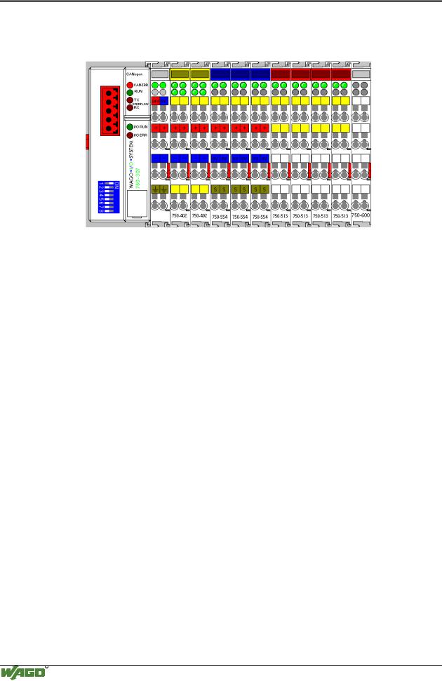
A coupler of the following configuration is projected:
Kl.1 Kl.2 Kl.3 Kl.4 Kl.5 Kl.6 Kl.7 Kl.8 Kl.9
Configuration for the full version:
|
Sub- |
|
|
Value |
|
|
Meaning |
|
|
|
|
|
|
|
|||
|
Index |
|
|
|
|
|
|
|
|
0 |
|
0x09 |
|
Total number of connected (9) and virtual (0) modules |
|
||
|
|
|
|
|
|
|
||
|
1 |
|
0x8063 |
|
digital, input, 4 channels, 1bit per channel, connected (mod. 1) |
|
||
|
|
|
|
|
|
|
||
|
2 |
|
0x8063 |
|
digital, input, 4 channels, 1bit per channel, connected (mod. 2) |
|
||
|
|
|
|
|
|
|
||
|
3 |
|
0x 8094 |
|
analog, output, 2 channels, 2byte per channel, connected (mod. 3) |
|
||
|
|
|
|
|
|
|
||
|
4 |
|
0x 8094 |
|
analog, output, 2 channels, 2byte per channel, connected (mod. 4) |
|
||
|
|
|
|
|
|
|
||
|
5 |
|
0x 8094 |
|
analog, output, 2 channels, 2byte per channel, connected (mod. 5) |
|
||
|
|
|
|
|
|
|
||
|
6 |
|
0x 8055 |
|
digital, output, 2 channels, 1bit per channel, connected (mod. 6) |
|
||
|
|
|
|
|
|
|
||
|
7 |
|
0x 8055 |
|
digital, output, 2 channels, 1bit per channel, connected (mod. 7) |
|
||
|
|
|
|
|
|
|
||
|
8 |
|
0x 8055 |
|
digital, output, 2 channels, 1bit per channel, connected (mod. 8) |
|
||
|
|
|
|
|
|
|
||
|
9 |
|
0x 8055 |
|
digital, output, 2 channels, 1bit per channel, connected (mod. 9) |
|
||
|
|
|
|
|
|
|
|
|
WAGO-I/O-SYSTEM 750
CANopen

CANopen • 167
Network Communication
As a second step, a coupler is protected which is a sub-quantity of the first one. The only modules used are module 2 and 8.
Kl.2 Kl.8
Configuration for the version mod. 2 and mod. 8 connected:
S-Idx. |
Value |
Meaning |
0 |
0x09 |
Total number of connected (2) and virtual (7) modules |
|
|
|
1 |
0x0063 |
digital, input, 4 channels, 1bit per channel, not conn.(mod. 1) |
|
|
|
2 |
0x8063 |
digital, input, 4 channels, 1bit per channel, connected (mod. 2) |
|
|
|
3 |
0x 0094 |
analog, output, 2 channels, 2byte per channel, not conn.(mod. 3) |
|
|
|
4 |
0x 0094 |
analog, output, 2 channels, 2byte per channel, not conn.(mod. 4) |
|
|
|
5 |
0x 0094 |
analog, output, 2 channels, 2byte per channel, not conn.(mod. 5) |
|
|
|
6 |
0x 0055 |
digital, output, 2 channels, 1bit per channel, not conn.(mod. 6) |
|
|
|
7 |
0x 0055 |
digital, output, 2 channels, 1bit per channel, not conn.(mod. 7) |
|
|
|
8 |
0x 8055 |
digital, output, 2 channels, 1bit per channel, connected (mod. 8) |
|
|
|
9 |
0x 0055 |
digital, output, 2 channels, 1bit per channel, not conn.(mod. 9) |
|
|
|
With regard to their entries in the object directory (connected modules), the behavior of both couplers is identical. Consequently, their behavior is also identical during PDO mapping.
Bit 4 must be set in index 0x6200, sub-index 1, for instance, to be able to set the 1st channel of the output module 8 (750-513).
This process is identical for both configurations.
If there was not an empty module configuration, in contrast to the above, bit 0 would have to be set for the 2nd configuration, index 0x6200, sub-index 1, in order to set the same output channel.
WAGO-I/O-SYSTEM 750
CANopen