

- •Important Comments
- •Legal Principles
- •Copyright
- •Personnel Qualification
- •Intended Use
- •Symbols
- •Font Conventions
- •Number Notation
- •Safety Notes
- •The WAGO-I/O-SYSTEM 750
- •System Description
- •Technical Data
- •Manufacturing Number
- •Component Update
- •Storage, Assembly and Transport
- •Mechanical Setup
- •Installation Position
- •Total Expansion
- •Assembly onto Carrier Rail
- •Carrier rail properties
- •WAGO DIN Rail
- •Spacing
- •Plugging and Removal of the Components
- •Assembly Sequence
- •Internal Bus / Data Contacts
- •Power Contacts
- •Wire connection
- •Power Supply
- •Isolation
- •System Supply
- •Connection
- •Alignment
- •Field Supply
- •Connection
- •Fusing
- •Supplementary power supply regulations
- •Supply example
- •Power Supply Unit
- •Grounding
- •Grounding the DIN Rail
- •Framework Assembly
- •Insulated Assembly
- •Grounding Function
- •Grounding Protection
- •Shielding (Screening)
- •General
- •Bus Conductors
- •Signal Conductors
- •WAGO Shield (Screen) Connecting System
- •Assembly Guidelines / Standards
- •Scope
- •Abbreviation
- •Fieldbus Controller
- •Fieldbus Controller 750-837, /02x-000, 750-838, /02x-000
- •Description
- •Hardware
- •View
- •Variants
- •Device supply
- •Fieldbus connection
- •Display elements
- •Configuration and programming interface
- •Operating mode switch
- •Hardware address (Module ID)
- •Setting the baud rate
- •Operating system
- •Start-up
- •PLC cycle
- •Process Image
- •General Structure
- •Fieldbus specific Process Data Architecture
- •Digital Input Modules
- •Digital Output Modules
- •Analog Input Modules
- •Analog Output Modules
- •Specialty Modules
- •System Modules
- •Data Exchange
- •Communication objects
- •Communication interfaces
- •Memory areas
- •Addressing
- •Fieldbus specific Addressing
- •Absolute Addresses
- •Calculate Addresses
- •Address Range for Flags
- •Example for Absolute Addresses
- •Programming the PFC with WAGO-I/O-PRO CAA
- •WAGO-I/O-PRO CAA Library Elements for CANopen
- •IEC 61131-3 Program transfer
- •Transmission via the serial interface
- •Transmission via the fieldbus
- •Starting up CANopen fieldbus nodes
- •Connecting the PC and fieldbus node
- •Checking and setting the Baud rate
- •Setting the module ID
- •Changing to the OPERATIONAL status
- •Turning on the analog input data
- •Application specific mapping
- •LED Display
- •Fieldbus status
- •Node Status – Blink code from the 'I/O' LED
- •Supply Voltage Status
- •Technical Data
- •I/O Modules
- •General
- •Digital Input Modules
- •Digital Output Modules
- •Analog Intput Modules
- •Analog Output Modules
- •Special Modules
- •System Modules
- •CANopen
- •Description
- •Network Architecture
- •Transmission Media
- •Type of Cable
- •Maximum Bus Length
- •Required Conductor Cross Section
- •Cabling
- •Network Topology
- •Interface Modules
- •Configuration Software
- •Network Communication
- •Communication Objects
- •Process Data Object - PDO
- •PDO Protocol
- •Service Data Object - SDO
- •SDO Protocol
- •Initiate SDO Download
- •Download SDO Segment
- •Initiate SDO Upload
- •Upload SDO Segment
- •SDO Examples
- •Synchronization Object - SYNC
- •SYNC Protocol
- •Emergency Object (EMCY)
- •EMCY Protocol
- •CANopen state diagram
- •INITIALIZATION
- •PRE-OPERATIONAL
- •OPERATIONAL
- •STOPPED
- •Network Management Objects
- •Module Control Protocols
- •Start Remote Node
- •Stop Remote Node
- •Enter Pre-Operational
- •Reset Node
- •Error Control Protocols
- •Node Guarding Protocol
- •Heartbeat Protocol
- •Bootup Protocol
- •Object Directory
- •Initialization
- •Communication Profile Area
- •Object 0x1000, Device Type
- •Object 0x1001, Error Register
- •Object 0x1003, Pre-defined Error Field
- •Object 0x1005, COB-ID SYNC message
- •Object 0x1006, Communication Cycle Period
- •Object 0x1008, Manufacturer Device Name
- •Object 0x1009, Manufacturer Hardware Version
- •Object 0x100A, Manufacturer Software Version
- •Object 0x100C, Guard Time
- •Object 0x100D, Life Time Factor
- •Object 0x1010, Store Parameters
- •Object 0x1011, Restore default Parameters
- •Object 0x1015, Inhibit Time Emergency Object
- •Object 0x1016, Consumer Heartbeat Time
- •Object 0x1017, Producer Heartbeat Time
- •Object 0x1018, Identity Object
- •Object 0x1200– 0x1201, Server SDO
- •Object 0x1280– 0x128F, Client SDO
- •Object 0x1400– 0x141F, Receive PDO Communication Parameter
- •Object 0x1600– 0x161F, Receive PDO Mapping Parameter
- •Object 0x1800– 0x181F, Transmit PDO Communication Parameter
- •Object 0x1A00 – 0x1A1F, Transmit PDO Mapping Parameter
- •Manufacturer Specific Profile Area
- •Object 0x2000, Digital Inputs
- •Object 0x2100, Digital Outputs
- •Object 0x2200, 1 Byte Special Modules, Inputs
- •Object 0x2300, 1 Byte Special Modules, Outputs
- •Object 0x2400, 2 Byte Special Modules, Inputs
- •Object 0x2500, 2 Byte Special Modules, Outputs
- •Object 0x2600, 3 Byte Special Modules, Inputs
- •Object 0x2700, 3 Byte Special Modules, Outputs
- •Object 0x2800, 4 Byte Special Modules, Inputs
- •Object 0x2900, 4 Byte Special Modules, Outputs
- •Object 0x3000, 5 Byte Special Modules, Inputs
- •Object 0x3100, 5 Byte Special Modules, Outputs
- •Object 0x3200, 6 Byte Special Modules, Inputs
- •Object 0x3300, 6 Byte Special Modules, Outputs
- •Object 0x3400, 7 Byte Special Modules, Inputs
- •Object 0x3500, 7 Byte Special Modules, Outputs
- •Object 0x3600, 8 Byte Special Modules, Inputs
- •Object 0x3700, 8 Byte Special Modules, Outputs
- •Object 0x4200-0x4202, Gateway Module Input
- •Object 0x4500, Spacer Module Configuration
- •Object 0x5000, Read Input Process Image
- •Object 0x5001, Write Output Process Image
- •Object 0x5200, Controller Configuration Object
- •Object 0x5201, Diagnostics Configuration Object
- •Standard Device Profile Area – DS 401
- •Object 0x6000, Digital Inputs
- •Object 0x6005, Global Interrupt Enable Digital 8-Bit
- •Object 0x6006, Interrupt Mask Any Change 8-Bit
- •Object 0x6007, Interrupt Mask Low-to-High 8-Bit
- •Object 0x6008, Interrupt Mask High-to-Low 8-Bit
- •Object 0x6200, Digital Outputs
- •Object 0x6206, Error Mode Output 8-Bit
- •Object 0x6207, Error Value Output 8-Bit
- •Object 0x6401, Analog Inputs 16 Bit
- •Object 0x6411, Analog Outputs 16 Bit
- •Object 0x6421, Analog Input Interrupt Trigger Selection
- •Object 0x6423, Analog Input Global Interrupt Enable
- •Object 0x6424, Analog Input Interrupt Upper Limit Integer
- •Object 0x6425, Analog Input Interrupt Lower Limit Integer
- •Object 0x6426, Analog Input Interrupt Delta Unsigned
- •Object 0x6443, Analog Output Error Mode
- •Object 0x6444, Analog Output Error Value Integer
- •Object 0x67FE, Error Behavior
- •Reserved Area
- •Object 0xA000, Integer8 IEC 61131-1 Input variables
- •Object 0xA040, Unsigned8 IEC 61131-1 Input variables
- •Object 0xA080, Boolean IEC 61131-1 Input variables
- •Object 0xA0C0, Integer16 IEC 61131-1 Input variables
- •PDO Transmission
- •Mapping
- •Transmit PDO1
- •Receive PDO1
- •Transmit PDO2
- •Receive PDO2
- •SYNC Monitoring
- •Node Guarding
- •Heartbeat Monitoring
- •Error Message (Emergency)
- •Diagnostic Message of I/O Modules
- •Use in Hazardous Environments
- •Foreword
- •Protective measures
- •Classification meeting CENELEC and IEC
- •Divisions
- •Explosion protection group
- •Unit categories
- •Temperature classes
- •Types of ignition protection
- •Classifications meeting the NEC 500
- •Divisions
- •Explosion protection groups
- •Temperature classes
- •Identification
- •For Europe
- •For America
- •Installation regulations
- •Glossary
- •Literature list
- •Index

136 • CANopen
Network Communication
5.3.1.3.1 SYNC Protocol
|
|
|
Sync Protokoll |
||||
Sync Producer |
Sync Consumer(s) |
||||||
request |
|
COB-ID = 128 |
|
|
indication(s) |
||
|
|
|
|||||
|
|
|
|
|
|||
|
|
|
|
|
|||
|
|
|
|
|
|
||
|
|
|
|
|
|
|
|
|
|
|
L = 0 |
|
|
|
|
|
|
|
|
|
|
|
|
|
|
|
|
|
|
|
|
|
|
|
|
|
|
|
|
Fig. 5-13: SYNC Protocol |
g012413x |
5.3.1.4 Emergency Object (EMCY)
Emergency objects are triggered by an internal error situation such as i.e. a module is removed during operation, or a module signals an error. The bus coupler then sends an emergency object to all connected devices (Broadcast), to broadcast the error occurred. The informed bus subscribers can then react accordingly by suitable error correction measures.
5.3.1.4.1 EMCY Protocol
|
|
|
|
|
|
EMCY Protokoll |
|
|
|
|
|
|
|
EMCY Producer |
|
|
|
|
|
EMCY Consumer(s) |
|||||||
|
0 |
2 |
3 |
8 |
|
|
|
|
indication(s) |
||||
|
|
|
|
|
|||||||||
|
|
|
|
|
|||||||||
|
|
|
|
|
|||||||||
request |
|
|
|
|
|
|
|
|
|
|
|
||
|
|
|
|
|
|
|
|
|
|
|
|
||
|
|
|
EEC |
|
ER |
|
MER |
|
|
|
|
|
|
|
|
|
|
|
|
|
|||||||
|
|
|
|
|
|
|
|
|
|
|
|
|
|
|
|
|
|
|
|
|
|
|
|
|
|
|
|
|
|
|
|
|
|
|
|
|
|
|
|
|
|
|
|
|
|
|
|
|
|
|
|
|
|
|
|
Fig. 5-14: EMCY Protocol |
g012414x |
More Information
A detailed description to the Emergency messages, please refer to chapter 5.3.9 "Error Message (Emergency)".
WAGO-I/O-SYSTEM 750
CANopen
CANopen • 137
Network Communication
5.3.2 Communication states of a CANopen fieldbus coupler/controller
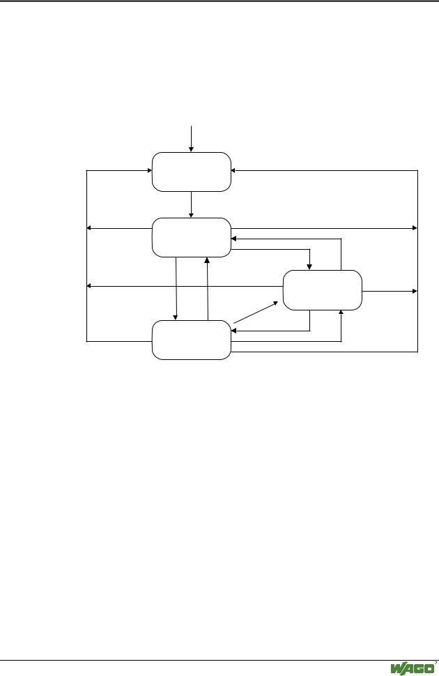
5.3.2.1 CANopen state diagram
The status diagram described in the following figure shows the individual communication states and possible transitions related to the CAN communication.
|
Power On |
|
Reset |
|
|
Communication |
Initialization |
Reset Node |
|
|
|
|
Initialisation finished |
|
|
Pre-Operational |
Enter Pre-Operational |
|
|
Stop Remote Node |
|
Enter |
|
|
Pre-Operational |
|
|
Start |
Stopped |
|
|
|
|
Remote |
Error |
|
Node |
|
|
|
Start Remote Node |
|
Operational |
Stop Remote Node |
Fig. 5-15: State diagram of the fieldbus coupler/controller |
g012422x |
5.3.2.2 INITIALIZATION
Following a power On or a reset (module ID unequal 0), the bus coupler is automatically in the INITIALIZATION status. In this status, the bus coupler performs a self-check to check all functions of its components and the communication interface. The process image is created on the basis of the connected modules and a possibly stored configuration, and the object directory initialized. If no errors are detected during the initialization phase the bus coupler automatically changes to the pre-operational status. If errors were found, a change to the STOP status takes place.
During initialization, the I/O-LED starts blinking orange and changes to red at its higher frequency. If initialization and the change to the pre-operational status have been successfully completed, the I/O LED is lit green and the RUN LED blinks. If errors have occurred (i.e. no end module connected) the I/O LED indicates the error type by a red blinking sequence (see LED status display). In this case, the STOP LED is lit red.
WAGO-I/O-SYSTEM 750
CANopen

138 • CANopen
Network Communication
5.3.2.3 PRE-OPERATIONAL
In this status, communication can be made via SDOs. Communication via PDOs is not possible. The SDOs allow for reading and writing in the entries of the object directories permitting for instance to re-configure the bus coupler by means of the configuration tool. Mapping, bus coupler parameters, IDs etc. can in this manner be adapted to the required conditions. The newly configured configuration can be saved in flash.
A change from the pre-operational status to the operational status is performed by means of the NMT service Start_Remote_Node.
In the pre-operational status the I/O LED is lit green and the RUN LED blinks.
5.3.2.4 OPERATIONAL
This status allows communication via SDOs and PDOs, it does, however, not allow different configurations. It is, for instance, not allowed to change the COB ID in the presence of a valid PDO. For a detailed description, please refer to the corresponding entries in the object directory.
The change from the operational status to the pre-operational status is performed with the NMT service Enter_Pre_Operational_State.
In the operational status, the I/O and the RUN LED are lit.
5.3.2.5 STOPPED
The Stopped status reflects an error status. This is the case if the NMT service Stop_Remote_Node was received or if a fatal internal error has occurred (i.e. module was removed during operation).
This status does not allow communication via SDOs or PDOs. Only the NMT services and the Node Guarding/Heartbeat (if activated) are performed.
You can quit the Stopped status via the NMT services Start_Remote_Node_Indication, Enter_Pre_Operational_State and Reset_Node.
The Stop LED is lit in the Stopped status.
WAGO-I/O-SYSTEM 750
CANopen