
- •Important Comments
- •Legal Principles
- •Copyright
- •Personnel Qualification
- •Intended Use
- •Symbols
- •Font Conventions
- •Number Notation
- •Safety Notes
- •The WAGO-I/O-SYSTEM 750
- •System Description
- •Technical Data
- •Manufacturing Number
- •Component Update
- •Storage, Assembly and Transport
- •Mechanical Setup
- •Installation Position
- •Total Expansion
- •Assembly onto Carrier Rail
- •Carrier rail properties
- •WAGO DIN Rail
- •Spacing
- •Plugging and Removal of the Components
- •Assembly Sequence
- •Internal Bus / Data Contacts
- •Power Contacts
- •Wire connection
- •Power Supply
- •Isolation
- •System Supply
- •Connection
- •Alignment
- •Field Supply
- •Connection
- •Fusing
- •Supplementary power supply regulations
- •Supply example
- •Power Supply Unit
- •Grounding
- •Grounding the DIN Rail
- •Framework Assembly
- •Insulated Assembly
- •Grounding Function
- •Grounding Protection
- •Shielding (Screening)
- •General
- •Bus Conductors
- •Signal Conductors
- •WAGO Shield (Screen) Connecting System
- •Assembly Guidelines / Standards
- •Scope
- •Abbreviation
- •Fieldbus Controller
- •Fieldbus Controller 750-837, /02x-000, 750-838, /02x-000
- •Description
- •Hardware
- •View
- •Variants
- •Device supply
- •Fieldbus connection
- •Display elements
- •Configuration and programming interface
- •Operating mode switch
- •Hardware address (Module ID)
- •Setting the baud rate
- •Operating system
- •Start-up
- •PLC cycle
- •Process Image
- •General Structure
- •Fieldbus specific Process Data Architecture
- •Digital Input Modules
- •Digital Output Modules
- •Analog Input Modules
- •Analog Output Modules
- •Specialty Modules
- •System Modules
- •Data Exchange
- •Communication objects
- •Communication interfaces
- •Memory areas
- •Addressing
- •Fieldbus specific Addressing
- •Absolute Addresses
- •Calculate Addresses
- •Address Range for Flags
- •Example for Absolute Addresses
- •Programming the PFC with WAGO-I/O-PRO CAA
- •WAGO-I/O-PRO CAA Library Elements for CANopen
- •IEC 61131-3 Program transfer
- •Transmission via the serial interface
- •Transmission via the fieldbus
- •Starting up CANopen fieldbus nodes
- •Connecting the PC and fieldbus node
- •Checking and setting the Baud rate
- •Setting the module ID
- •Changing to the OPERATIONAL status
- •Turning on the analog input data
- •Application specific mapping
- •LED Display
- •Fieldbus status
- •Node Status – Blink code from the 'I/O' LED
- •Supply Voltage Status
- •Technical Data
- •I/O Modules
- •General
- •Digital Input Modules
- •Digital Output Modules
- •Analog Intput Modules
- •Analog Output Modules
- •Special Modules
- •System Modules
- •CANopen
- •Description
- •Network Architecture
- •Transmission Media
- •Type of Cable
- •Maximum Bus Length
- •Required Conductor Cross Section
- •Cabling
- •Network Topology
- •Interface Modules
- •Configuration Software
- •Network Communication
- •Communication Objects
- •Process Data Object - PDO
- •PDO Protocol
- •Service Data Object - SDO
- •SDO Protocol
- •Initiate SDO Download
- •Download SDO Segment
- •Initiate SDO Upload
- •Upload SDO Segment
- •SDO Examples
- •Synchronization Object - SYNC
- •SYNC Protocol
- •Emergency Object (EMCY)
- •EMCY Protocol
- •CANopen state diagram
- •INITIALIZATION
- •PRE-OPERATIONAL
- •OPERATIONAL
- •STOPPED
- •Network Management Objects
- •Module Control Protocols
- •Start Remote Node
- •Stop Remote Node
- •Enter Pre-Operational
- •Reset Node
- •Error Control Protocols
- •Node Guarding Protocol
- •Heartbeat Protocol
- •Bootup Protocol
- •Object Directory
- •Initialization
- •Communication Profile Area
- •Object 0x1000, Device Type
- •Object 0x1001, Error Register
- •Object 0x1003, Pre-defined Error Field
- •Object 0x1005, COB-ID SYNC message
- •Object 0x1006, Communication Cycle Period
- •Object 0x1008, Manufacturer Device Name
- •Object 0x1009, Manufacturer Hardware Version
- •Object 0x100A, Manufacturer Software Version
- •Object 0x100C, Guard Time
- •Object 0x100D, Life Time Factor
- •Object 0x1010, Store Parameters
- •Object 0x1011, Restore default Parameters
- •Object 0x1015, Inhibit Time Emergency Object
- •Object 0x1016, Consumer Heartbeat Time
- •Object 0x1017, Producer Heartbeat Time
- •Object 0x1018, Identity Object
- •Object 0x1200– 0x1201, Server SDO
- •Object 0x1280– 0x128F, Client SDO
- •Object 0x1400– 0x141F, Receive PDO Communication Parameter
- •Object 0x1600– 0x161F, Receive PDO Mapping Parameter
- •Object 0x1800– 0x181F, Transmit PDO Communication Parameter
- •Object 0x1A00 – 0x1A1F, Transmit PDO Mapping Parameter
- •Manufacturer Specific Profile Area
- •Object 0x2000, Digital Inputs
- •Object 0x2100, Digital Outputs
- •Object 0x2200, 1 Byte Special Modules, Inputs
- •Object 0x2300, 1 Byte Special Modules, Outputs
- •Object 0x2400, 2 Byte Special Modules, Inputs
- •Object 0x2500, 2 Byte Special Modules, Outputs
- •Object 0x2600, 3 Byte Special Modules, Inputs
- •Object 0x2700, 3 Byte Special Modules, Outputs
- •Object 0x2800, 4 Byte Special Modules, Inputs
- •Object 0x2900, 4 Byte Special Modules, Outputs
- •Object 0x3000, 5 Byte Special Modules, Inputs
- •Object 0x3100, 5 Byte Special Modules, Outputs
- •Object 0x3200, 6 Byte Special Modules, Inputs
- •Object 0x3300, 6 Byte Special Modules, Outputs
- •Object 0x3400, 7 Byte Special Modules, Inputs
- •Object 0x3500, 7 Byte Special Modules, Outputs
- •Object 0x3600, 8 Byte Special Modules, Inputs
- •Object 0x3700, 8 Byte Special Modules, Outputs
- •Object 0x4200-0x4202, Gateway Module Input
- •Object 0x4500, Spacer Module Configuration
- •Object 0x5000, Read Input Process Image
- •Object 0x5001, Write Output Process Image
- •Object 0x5200, Controller Configuration Object
- •Object 0x5201, Diagnostics Configuration Object
- •Standard Device Profile Area – DS 401
- •Object 0x6000, Digital Inputs
- •Object 0x6005, Global Interrupt Enable Digital 8-Bit
- •Object 0x6006, Interrupt Mask Any Change 8-Bit
- •Object 0x6007, Interrupt Mask Low-to-High 8-Bit
- •Object 0x6008, Interrupt Mask High-to-Low 8-Bit
- •Object 0x6200, Digital Outputs
- •Object 0x6206, Error Mode Output 8-Bit
- •Object 0x6207, Error Value Output 8-Bit
- •Object 0x6401, Analog Inputs 16 Bit
- •Object 0x6411, Analog Outputs 16 Bit
- •Object 0x6421, Analog Input Interrupt Trigger Selection
- •Object 0x6423, Analog Input Global Interrupt Enable
- •Object 0x6424, Analog Input Interrupt Upper Limit Integer
- •Object 0x6425, Analog Input Interrupt Lower Limit Integer
- •Object 0x6426, Analog Input Interrupt Delta Unsigned
- •Object 0x6443, Analog Output Error Mode
- •Object 0x6444, Analog Output Error Value Integer
- •Object 0x67FE, Error Behavior
- •Reserved Area
- •Object 0xA000, Integer8 IEC 61131-1 Input variables
- •Object 0xA040, Unsigned8 IEC 61131-1 Input variables
- •Object 0xA080, Boolean IEC 61131-1 Input variables
- •Object 0xA0C0, Integer16 IEC 61131-1 Input variables
- •PDO Transmission
- •Mapping
- •Transmit PDO1
- •Receive PDO1
- •Transmit PDO2
- •Receive PDO2
- •SYNC Monitoring
- •Node Guarding
- •Heartbeat Monitoring
- •Error Message (Emergency)
- •Diagnostic Message of I/O Modules
- •Use in Hazardous Environments
- •Foreword
- •Protective measures
- •Classification meeting CENELEC and IEC
- •Divisions
- •Explosion protection group
- •Unit categories
- •Temperature classes
- •Types of ignition protection
- •Classifications meeting the NEC 500
- •Divisions
- •Explosion protection groups
- •Temperature classes
- •Identification
- •For Europe
- •For America
- •Installation regulations
- •Glossary
- •Literature list
- •Index

46• Fieldbus Controller 750-837, /02x-000, 750-838, /02x-000 Hardware
3.1.2.6 Configuration and programming interface
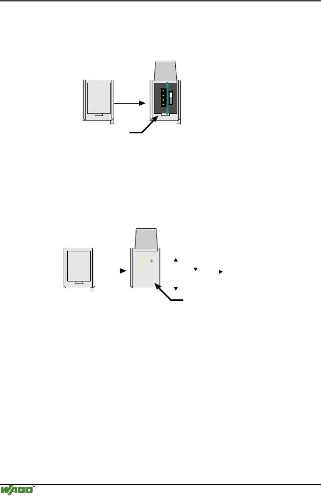
The configuration and programming interface is located behind the cover flap. This is used to communicate with WAGO-I/O-CHECK and for firmware transfer.
open flap
Configuration and programming interface
Fig. 3-6: Configuration and programming interface |
g01xx07e |
The communication cable (750-920) is connected to the 4 pole header.
3.1.2.7 Operating mode switch
The operating mode switch is located behind the cover flap beside the configuration and programming interface.
|
|
|
open |
|
|
|
|
|
|
|
|
|
|
|
||
|
|
|
|
|
|
|
|
|
|
|
|
|
|
|||
|
|
|
flap |
|
|
|
|
|
|
|
Run |
Stop |
Reset |
|||
|
|
|
|
|
|
|
|
|
|
|||||||
|
|
|
|
|
|
|
|
|
|
|||||||
|
|
|
|
|
|
|
|
|
||||||||
|
|
|
|
|
|
|
|
|
|
|
|
|
|
|
|
|
|
|
|
|
|
|
|
|
|
|
|
|
|
|
|
|
(pushing down) |
|
|
|
|
|
|
|
|
|
|
|
|
|
Update firmware |
|||
|
|
|
|
|
|
|
|
|
|
|
|
|
|
|||
|
|
|
|
|
|
|
|
|
|
|
|
|
|
|||
|
|
|
|
|
|
|
|
|
|
|
|
|
mode switch |
|||
|
|
|
|
|
|
|
|
|
|
|
|
|
||||
|
|
|
|
|
|
|
|
|
|
|
|
|
||||
Fig. 3-7: Operating mode switch |
|
|||||||||||||||
|
|
|
|
g01xx08e |
The switch is a push/slide switch with 3 settings and a hold-to-run function.
Operating mode switch |
Function |
From middle to top position |
Activate program processing (RUN) |
|
|
From top to middle position |
Stop program processing (STOP) |
|
|
Lower position, bootstrap |
For original loading of firmware, |
|
not necessary for user |
|
|
Push down |
Hardware reset |
(i.e.with a screwdriver) |
All outputs are reset; variables are set to 0 or to FALSE |
|
or to an initial value. |
|
Retain variables or flags are not changed. |
|
The hardware reset can be performed with STOP as well |
|
as RUN in any position of the operating mode switch! |
|
|
An operating mode is internally changed at the end of a PLC cycle.
WAGO-I/O-SYSTEM 750
CANopen

Fieldbus Controller 750-837, /02x-000, 750-838, /02x-000 |
• 47 |
Hardware |
|
|
|
Attention
If outputs are set when switching over the operating mode switch from RUN to STOP, they remain set! Switching off the software side i.e. by initiators, are ineffective, because the program is no longer processed.
Note
With "GET_STOP_VALUE" (library "System.lib") WAGO-I/O-PRO CAA provides a function which serves to recognize the last cycle prior to a program stop giving the user the possibility to program the behavior of the controller in case of a STOP. With the aid of this function the controller outputs can be switched to a safe condition.
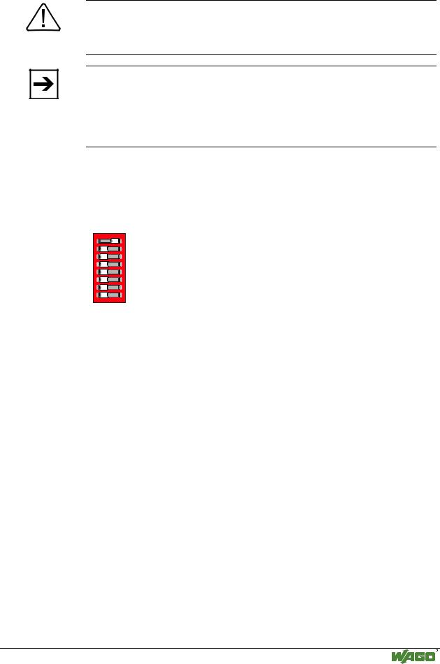
3.1.2.8 Hardware address (Module ID)
The DIP switch is used both for parameterizing the fieldbus coupler and for setting the module ID. This module ID is necessary for calculating the COB IDs (e.g. of PDO1...4, 1. Server SDO, etc.).
1
2
3
4
5
6
7
8
1 2 |
ON |
3 |
|
4 |
|
5 |
|
6 |
|
7 |
|
8 |
|
ON
Fig. 3-8: Setting of station (node) address |
g012440x |
The binary significance of the individual DIP switches increases according to the switch number, i.e. the module ID 1 is set by DIP1 = ON, the module ID 8 by DIP4 = ON, etc.
The nodes of the WAGO-I/O-SYSTEM can have module IDs from 1 to 127.
3.1.2.9 Setting the baud rate
The bus coupler supports 9 different Baud rates. DIP switches are used for setting.
The bus coupler changes to the configuration mode using the set module ID = 0 (all DIP switches off) with subsequent power On. The currently set baud rate is displayed in this status. The baud rate display can be viewed by the top LED group (STOP, RUN, Tx-, Rx-Overflow), whereby STOP = Switch 1, RUN = Switch 2, Tx-Overflow = Switch 3 and Rx-Overflow = Switch 4. The currently set baud rate is displayed by the corresponding LEDs blinking slowly. Now the new baud rate can be set using the DIP switch, by switching the corresponding DIP switches to 'ON'.
The set configuration is saved by displacing DIP8 to ´on´. Following saving, the new baud rate is displayed by the corresponding LEDs having steady light.
WAGO-I/O-SYSTEM 750
CANopen

48• Fieldbus Controller 750-837, /02x-000, 750-838, /02x-000 Hardware
Exception: the baud rate of 1MBaud, this being displayed by all 4 LEDs blinking/being lit.
Example: |
125 kB: Tx-Overflow LED blink / are lit |
|
250 kB: STOP and RUN LED blink / are lit |
1 ON
2
3 |
4
5
6
7
8 |
Fig. 3-9: Example: Saving the baud rate 125 kB |
g012441x |
In this status no data exchange via CAN is possible.
DIP |
Function |
1 |
800 |
500 |
250 |
125 |
100 |
50 |
20 |
10 |
is displayed |
|
|
|
|
Mbit |
kB |
kB |
kB |
kB |
kB |
kB |
kB |
kB |
by LED |
1 |
(LSB) |
Baud rate |
0 |
1 |
0 |
1 |
0 |
1 |
0 |
1 |
0 |
STOP |
2 |
|
Baud rate |
0 |
0 |
1 |
1 |
0 |
0 |
1 |
1 |
0 |
RUN |
3 |
|
Baud rate |
0 |
0 |
0 |
0 |
1 |
1 |
1 |
1 |
0 |
Tx-Overflow |
4 |
(MSB) |
Baud rate |
0 |
0 |
0 |
0 |
0 |
0 |
0 |
0 |
1 |
Rx-Overflow |
5 |
|
|
|
|
|
|
|
|
|
|
|
|
6 |
|
|
|
|
|
|
|
|
|
|
|
|
7 |
|
|
|
|
|
|
|
|
|
|
|
|
8 |
|
Accept- |
´off´ -> |
´on´ : |
Accepting |
the |
configuration |
settings |
|
|
|
|
|
|
ance |
|
|
|
|
|
|
|
|
|
|
Once the baud rate setting / baud rate check is completed, switch off the operating voltage knowing that only the DIP value will be used to calculate the IDs which has been set during power ON. When switched off, the desired module ID (=1 as delivered) can be set on the DIP.
Default baud rate: 125 kB.
WAGO-I/O-SYSTEM 750
CANopen