

PROCEDURE CALLS, INTERRUPTS, AND EXCEPTIONS
A return from an interrupt or exception handler is initiated with the IRET instruction. The IRET instruction is similar to the far RET instruction, except that it also restores the contents of the EFLAGS register for the interrupted procedure. When executing a return from an interrupt or exception handler from the same privilege level as the interrupted procedure, the processor performs these actions:
1.Restores the CS and EIP registers to their values prior to the interrupt or exception.
2.Restores the EFLAGS register.
3.Increments the stack pointer appropriately.
4.Resumes execution of the interrupted procedure.
When executing a return from an interrupt or exception handler from a different privilege level than the interrupted procedure, the processor performs these actions:
1.Performs a privilege check.
2.Restores the CS and EIP registers to their values prior to the interrupt or exception.
3.Restores the EFLAGS register.
4.Restores the SS and ESP registers to their values prior to the interrupt or exception, resulting in a stack switch back to the stack of the interrupted procedure.
5.Resumes execution of the interrupted procedure.
6.4.2Calls to Interrupt or Exception Handler Tasks
Interrupt and exception handler routines can also be executed in a separate task. Here, an interrupt or exception causes a task switch to a handler task. The handler task is given its own address space and (optionally) can execute at a higher protection level than application programs or tasks.
The switch to the handler task is accomplished with an implicit task call that references a task gate descriptor. The task gate provides access to the address space for the handler task. As part of the task switch, the processor saves complete state information for the interrupted program or task. Upon returning from the handler task, the state of the interrupted program or task is restored and execution continues. See Chapter 5, “Interrupt and Exception Handling,” in the Intel® 64 and IA-32 Architectures Software Developer’s Manual, Volume 3B, for more information on handling interrupts and exceptions through handler tasks.
6.4.3Interrupt and Exception Handling in Real-Address Mode
When operating in real-address mode, the processor responds to an interrupt or exception with an implicit far call to an interrupt or exception handler. The processor uses the interrupt or exception vector number as an index into an interrupt table. The
Vol. 1 6-17
PROCEDURE CALLS, INTERRUPTS, AND EXCEPTIONS
interrupt table contains instruction pointers to the interrupt and exception handler procedures.
The processor saves the state of the EFLAGS register, the EIP register, the CS register, and an optional error code on the stack before switching to the handler procedure.
A return from the interrupt or exception handler is carried out with the IRET instruction.
See Chapter 15, “8086 Emulation,” in the Intel® 64 and IA-32 Architectures Software Developer’s Manual, Volume 3A, for more information on handling interrupts and exceptions in real-address mode.
6.4.4INT n, INTO, INT 3, and BOUND Instructions
The INT n, INTO, INT 3, and BOUND instructions allow a program or task to explicitly call an interrupt or exception handler. The INT n instruction uses an interrupt vector as an argument, which allows a program to call any interrupt handler.
The INTO instruction explicitly calls the overflow exception (#OF) handler if the overflow flag (OF) in the EFLAGS register is set. The OF flag indicates overflow on arithmetic instructions, but it does not automatically raise an overflow exception. An overflow exception can only be raised explicitly in either of the following ways:
•Execute the INTO instruction.
•Test the OF flag and execute the INT n instruction with an argument of 4 (the vector number of the overflow exception) if the flag is set.
Both the methods of dealing with overflow conditions allow a program to test for overflow at specific places in the instruction stream.
The INT 3 instruction explicitly calls the breakpoint exception (#BP) handler.
The BOUND instruction explicitly calls the BOUND-range exceeded exception (#BR) handler if an operand is found to be not within predefined boundaries in memory. This instruction is provided for checking references to arrays and other data structures.
Like the overflow exception, the BOUND-range exceeded exception can only be raised explicitly with the BOUND instruction or the INT n instruction with an argument of 5 (the vector number of the bounds-check exception). The processor does not implicitly perform bounds checks and raise the BOUND-range exceeded exception.
6.4.5Handling Floating-Point Exceptions
When operating on individual or packed floating-point values, the IA-32 architecture supports a set of six floating-point exceptions. These exceptions can be generated during operations performed by the x87 FPU instructions or by SSE/SSE2/SSE3 instructions. When an x87 FPU instruction (including the FISTTP instruction in SSE3) generates one or more of these exceptions, it in turn generates floating-point error
6-18 Vol. 1
PROCEDURE CALLS, INTERRUPTS, AND EXCEPTIONS
exception (#MF); when an SSE/SSE2/SSE3 instruction generates a floating-point exception, it in turn generates SIMD floating-point exception (#XF).
See the following sections for further descriptions of the floating-point exceptions, how they are generated, and how they are handled:
•Section 4.9.1, “Floating-Point Exception Conditions,” and Section 4.9.3, “Typical Actions of a Floating-Point Exception Handler”
•Section 8.4, “x87 FPU Floating-Point Exception Handling,” and Section 8.5, “x87 FPU Floating-Point Exception Conditions”
•Section 11.5.1, “SIMD Floating-Point Exceptions”
•Interrupt Behavior
6.4.6Interrupt and Exception Behavior in 64-Bit Mode
64-bit extensions expand the legacy IA-32 interrupt-processing and exceptionprocessing mechanism to allow support for 64-bit operating systems and applications. Changes include:
•All interrupt handlers pointed to by the IDT are 64-bit code (does not apply to the SMI handler).
•The size of interrupt-stack pushes is fixed at 64 bits. The processor uses 8-byte, zero extended stores.
•The stack pointer (SS:RSP) is pushed unconditionally on interrupts. In legacy environments, this push is conditional and based on a change in current privilege level (CPL).
•The new SS is set to NULL if there is a change in CPL.
•IRET behavior changes.
•There is a new interrupt stack-switch mechanism.
•The alignment of interrupt stack frame is different.
6.5PROCEDURE CALLS FOR BLOCK-STRUCTURED LANGUAGES
The IA-32 architecture supports an alternate method of performing procedure calls with the ENTER (enter procedure) and LEAVE (leave procedure) instructions. These instructions automatically create and release, respectively, stack frames for called procedures. The stack frames have predefined spaces for local variables and the necessary pointers to allow coherent returns from called procedures. They also allow scope rules to be implemented so that procedures can access their own local variables and some number of other variables located in other stack frames.
Vol. 1 6-19
PROCEDURE CALLS, INTERRUPTS, AND EXCEPTIONS
ENTER and LEAVE offer two benefits:
•They provide machine-language support for implementing block-structured languages, such as C and Pascal.
•They simplify procedure entry and exit in compiler-generated code.
6.5.1ENTER Instruction
The ENTER instruction creates a stack frame compatible with the scope rules typically used in block-structured languages. In block-structured languages, the scope of a procedure is the set of variables to which it has access. The rules for scope vary among languages. They may be based on the nesting of procedures, the division of the program into separately compiled files, or some other modularization scheme.
ENTER has two operands. The first specifies the number of bytes to be reserved on the stack for dynamic storage for the procedure being called. Dynamic storage is the memory allocated for variables created when the procedure is called, also known as automatic variables. The second parameter is the lexical nesting level (from 0 to 31) of the procedure. The nesting level is the depth of a procedure in a hierarchy of procedure calls. The lexical level is unrelated to either the protection privilege level or to the I/O privilege level of the currently running program or task.
ENTER, in the following example, allocates 2 Kbytes of dynamic storage on the stack and sets up pointers to two previous stack frames in the stack frame for this procedure:
ENTER 2048,3
The lexical nesting level determines the number of stack frame pointers to copy into the new stack frame from the preceding frame. A stack frame pointer is a doubleword used to access the variables of a procedure. The set of stack frame pointers used by a procedure to access the variables of other procedures is called the display. The first doubleword in the display is a pointer to the previous stack frame. This pointer is used by a LEAVE instruction to undo the effect of an ENTER instruction by discarding the current stack frame.
After the ENTER instruction creates the display for a procedure, it allocates the dynamic local variables for the procedure by decrementing the contents of the ESP register by the number of bytes specified in the first parameter. This new value in the ESP register serves as the initial top-of-stack for all PUSH and POP operations within the procedure.
To allow a procedure to address its display, the ENTER instruction leaves the EBP register pointing to the first doubleword in the display. Because stacks grow down, this is actually the doubleword with the highest address in the display. Data manipulation instructions that specify the EBP register as a base register automatically address locations within the stack segment instead of the data segment.
The ENTER instruction can be used in two ways: nested and non-nested. If the lexical level is 0, the non-nested form is used. The non-nested form pushes the contents of
6-20 Vol. 1
PROCEDURE CALLS, INTERRUPTS, AND EXCEPTIONS
the EBP register on the stack, copies the contents of the ESP register into the EBP register, and subtracts the first operand from the contents of the ESP register to allocate dynamic storage. The non-nested form differs from the nested form in that no stack frame pointers are copied. The nested form of the ENTER instruction occurs when the second parameter (lexical level) is not zero.
The following pseudo code shows the formal definition of the ENTER instruction. STORAGE is the number of bytes of dynamic storage to allocate for local variables, and LEVEL is the lexical nesting level.
PUSH EBP; FRAME_PTR ← ESP; IF LEVEL > 0
THEN
DO (LEVEL − 1) times EBP ← EBP − 4;
PUSH Pointer(EBP); (* doubleword pointed to by EBP *)
OD;
PUSH FRAME_PTR;
FI;
EBP ← FRAME_PTR; ESP ← ESP − STORAGE;
The main procedure (in which all other procedures are nested) operates at the highest lexical level, level 1. The first procedure it calls operates at the next deeper lexical level, level 2. A level 2 procedure can access the variables of the main program, which are at fixed locations specified by the compiler. In the case of level 1, the ENTER instruction allocates only the requested dynamic storage on the stack because there is no previous display to copy.
A procedure that calls another procedure at a lower lexical level gives the called procedure access to the variables of the caller. The ENTER instruction provides this access by placing a pointer to the calling procedure's stack frame in the display.
A procedure that calls another procedure at the same lexical level should not give access to its variables. In this case, the ENTER instruction copies only that part of the display from the calling procedure which refers to previously nested procedures operating at higher lexical levels. The new stack frame does not include the pointer for addressing the calling procedure’s stack frame.
The ENTER instruction treats a re-entrant procedure as a call to a procedure at the same lexical level. In this case, each succeeding iteration of the re-entrant procedure can address only its own variables and the variables of the procedures within which it is nested. A re-entrant procedure always can address its own variables; it does not require pointers to the stack frames of previous iterations.
By copying only the stack frame pointers of procedures at higher lexical levels, the ENTER instruction makes certain that procedures access only those variables of higher lexical levels, not those at parallel lexical levels (see Figure 6-6).
Vol. 1 6-21

PROCEDURE CALLS, INTERRUPTS, AND EXCEPTIONS
Main (Lexical Level 1)
Procedure A (Lexical Level 2)
Procedure B (Lexical Level 3)
Procedure C (Lexical Level 3)
Procedure D (Lexical Level 4)
Figure 6-6. Nested Procedures
Block-structured languages can use the lexical levels defined by ENTER to control access to the variables of nested procedures. In Figure 6-6, for example, if procedure A calls procedure B which, in turn, calls procedure C, then procedure C will have access to the variables of the MAIN procedure and procedure A, but not those of procedure B because they are at the same lexical level. The following definition describes the access to variables for the nested procedures in Figure 6-6.
1.MAIN has variables at fixed locations.
2.Procedure A can access only the variables of MAIN.
3.Procedure B can access only the variables of procedure A and MAIN. Procedure B cannot access the variables of procedure C or procedure D.
4.Procedure C can access only the variables of procedure A and MAIN. Procedure C cannot access the variables of procedure B or procedure D.
5.Procedure D can access the variables of procedure C, procedure A, and MAIN. Procedure D cannot access the variables of procedure B.
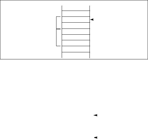
In Figure 6-7, an ENTER instruction at the beginning of the MAIN procedure creates three doublewords of dynamic storage for MAIN, but copies no pointers from other stack frames. The first doubleword in the display holds a copy of the last value in the EBP register before the ENTER instruction was executed. The second doubleword holds a copy of the contents of the EBP register following the ENTER instruction. After the instruction is executed, the EBP register points to the first doubleword pushed on the stack, and the ESP register points to the last doubleword in the stack frame.
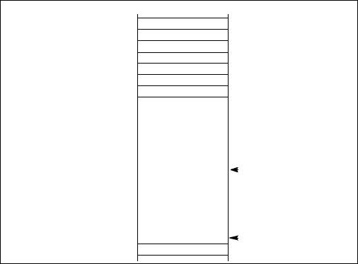
When MAIN calls procedure A, the ENTER instruction creates a new display (see Figure 6-8). The first doubleword is the last value held in MAIN's EBP register. The second doubleword is a pointer to MAIN's stack frame which is copied from the second doubleword in MAIN's display. This happens to be another copy of the last value held in MAIN’s EBP register. Procedure A can access variables in MAIN because MAIN is at level 1.
6-22 Vol. 1
PROCEDURE CALLS, INTERRUPTS, AND EXCEPTIONS
Therefore the base address for the dynamic storage used in MAIN is the current address in the EBP register, plus four bytes to account for the saved contents of MAIN’s EBP register. All dynamic variables for MAIN are at fixed, positive offsets from this value.
Old EBP |
|
EBP |
|
Display
Main’s EBP
Dynamic
Storage
 ESP
ESP
Figure 6-7. Stack Frame After Entering the MAIN Procedure
|
|
|
|
|
|
|
|
|
|
|
|
|
|
|
|
|
|
|
|
|
|
|
|
|
|
|
|
|
|
|
|
|
|
|
|
|
|
|
Old EBP |
|
|
|
||
|
|
|
Main’s EBP |
|
|
|
||
|
|
|
|
|
|
|
|
|
|
|
|
|
|
|
|
|
|
|
|
|
|
|
|
|
|
|
Display |
|
|
Main’s EBP |
|
|
EBP |
||
|
||||||||
|
|
Main’s EBP |
|
|
|
|
|
|
|
|
|
|
|
|
|||
|
|
|
Procedure A’s EBP |
|
|
|
||
Dynamic |
|
|
|
|
|
|
|
|
Storage |
|
|
|
|
|
|
|
ESP |
|
|
|
|
|
|
|
|
|
|
|
|
|
|
|
|
|
|
|
|
|
|
|
|
|
|
|
|
|
|
|
|
|
|
|
|
|
|
|
|
|
|
|
|
|
|
|
|
|
|
|
|
|
|
Figure 6-8. Stack Frame After Entering Procedure A
When procedure A calls procedure B, the ENTER instruction creates a new display (see Figure 6-9). The first doubleword holds a copy of the last value in procedure A’s EBP register. The second and third doublewords are copies of the two stack frame pointers in procedure A’s display. Procedure B can access variables in procedure A and MAIN by using the stack frame pointers in its display.
Vol. 1 6-23
PROCEDURE CALLS, INTERRUPTS, AND EXCEPTIONS
When procedure B calls procedure C, the ENTER instruction creates a new display for procedure C (see Figure 6-10). The first doubleword holds a copy of the last value in procedure B’s EBP register. This is used by the LEAVE instruction to restore procedure B’s stack frame. The second and third doublewords are copies of the two stack frame pointers in procedure A’s display. If procedure C were at the next deeper lexical level from procedure B, a fourth doubleword would be copied, which would be the stack frame pointer to procedure B’s local variables.
Note that procedure B and procedure C are at the same level, so procedure C is not intended to access procedure B’s variables. This does not mean that procedure C is completely isolated from procedure B; procedure C is called by procedure B, so the pointer to the returning stack frame is a pointer to procedure B’s stack frame. In addition, procedure B can pass parameters to procedure C either on the stack or through variables global to both procedures (that is, variables in the scope of both procedures).
Old EBP
Main’s EBP
|
|
|
Main’s EBP |
|
|
|
|
|
|
Main’s EBP |
|
|
|
|
|
|
Procedure A’s EBP |
|
|
|
|
|
|
|
|
|
EBP |
|
|
|
|
|
|
|
|
|
|
|
|
|
|
|
|
|
Procedure A’s EBP |
|
|
|
|
|
|
|
|
||
Display |
|
|
Main’s EBP |
|
|
|
|
|
Procedure A’s EBP |
|
|
|
|
|
|
|
|
|
|
|
|
|
|
Procedure B’s EBP |
|
|
|
Dynamic |
|
|
|
|
|
|
|
|
|
|
|||
Storage |
|
|
|
|
ESP |
|
|
|
|
||||
|
|
|
|
|
|
|
|
|
|
|
|
|
|
Figure 6-9. Stack Frame After Entering Procedure B
6-24 Vol. 1
PROCEDURE CALLS, INTERRUPTS, AND EXCEPTIONS
Old EBP
Main’s EBP
Main’s EBP
Main’s EBP
Procedure A’s EBP
|
|
|
Procedure A’s EBP |
|
|
|
||
|
|
|
Main’s EBP |
|
|
|
||
|
|
|
Procedure A’s EBP |
|
|
|
||
|
|
|
Procedure B’s EBP |
|
|
|||
|
|
|
|
|
|
|
|
EBP |
|
|
|
|
|
|
|
|
|
|
|
|
|
|
|
|
|
|
|
|
|
Procedure B’s EBP |
|
|
|||
|
|
|||||||
Display |
|
|
Main’s EBP |
|
|
|
||
|
|
Procedure A’s EBP |
|
|
|
|||
|
|
|
|
|
||||
|
|
|
Procedure C’s EBP |
|
|
|||
Dynamic |
|
|
|
|
|
|
|
|
|
|
|
|
|
|
|
|
|
|
|
|
|
|
|
|
|
|
Storage |
|
|
|
|
|
|
|
ESP |
|
|
|
|
|
|
|
||
|
|
|
|
|
|
|
|
|
|
|
|
|
|
|
|
|
|
Figure 6-10. Stack Frame After Entering Procedure C
Vol. 1 6-25