

Ceramic Technology and Processing, King
.pdfFiring 283
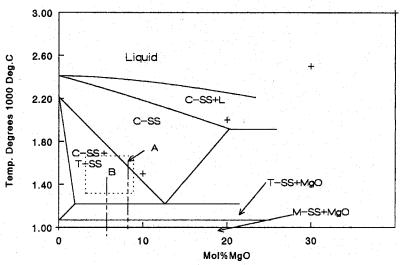
crystal system, but the amount of MgO is variable within the limits shown in the diagram. The region where tetragonal and cubic coexist is of particular interest and commercial importance, and will be discussed at some length.
Fully stabilized zirconia with MgO is a brittle ceramic of little commercial interest. However, if it is only partially stabilized, the ceramic system is of great interest. The area of concern in Figure 8.24 is the dashedlined box containing two compositions marked by vertical dashed lines. In the lower part of the diagram, are the T-MgO and M-MgO regions. Decomposition of the solid solutions is sluggish and does not occur in a normal cool down. One does not generally find MgO. Long aging in these regions will cause decomposition, but this does not normally occur in conventional processing.
Look at the composition on the right. Zirconia is batched with magnesia, milled, dried, and pressed into a part such as a small disc. It is set and fired above the phase boundary into the cubic solid solution region. This temperature is dependant on %MgO, becoming higher as the MgO content decreases, as shown in the phase diagram with the cubic boundary sloping up to the left. In the sketch, the composition was selected to make this temperature about 1800 °C, which is about as high as a gas kiln can fire unless one has special equipment. Even then, oxygen enrichment may be needed in a gas-fired kiln. The sample will sinter to near full density if prepared correctly. It will be monophased cubic with a coarse (40-60 μm) grain structure because of the high temperature. The phase diagram, and not the particle size of the starting powder, dictates the temperature. Unlike other ceramics, the size of the powder particles influences the sintering temperature. However in this example, the temperature is a consequence of the composition not the particle size.
As the ceramic cools, it drops into the C-SS, T-SS area, and the tetragonal phase precipitates out as small (about 0.2 μm), lenticular particles enclosed in the cubic matrix. One can predetermine the tetragonal phase amount from the phase diagram. As expected, there is less tetragonal when close to the cubic boundary, and more when further to the left. This can be estimated by the inverse lever law. Draw a vertical line at the body's composition in the phase diagram. Next, draw a horizontal line at the selected temperature and measure its length in the C-SS, T-SS phase region to the vertical composition and measure the other side up to the left
284 Ceramic Technology and Processing
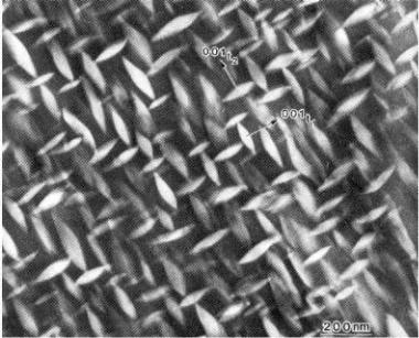
boundary of the phase region. The inverse ratio of these lengths is the equilibrium ratio of the amounts of the two phases. Using transmission electron microscopy, Heuer photographed this structure.2 This is shown in Figure 8.25.
Figure 8.25: Tetragonal Zirconia Inclusions. Tetragonal zirconia inclusions in the cubic solid solution phase impart toughness to the ceramic. Scale bar 0.1 μm.
Look again at the phase diagram. As the temperature decreases, the amount of the tetragonal increases. To reach equilibrium, the ceramic has to be aged at an intermediate temperature such as 1500 °C for about an hour. One can craft the ceramic using the tools in the following list:
•original composition,
•sintering temperature,
•sintering time,
Firing 285
•annealing temperature, and
•annealing time.
Use these tools to craft the ceramic and to optimize the properties that one seeks. After identifying the independent variables, one can craft a statistically-designed experiment and optimize the ceramic manufacturing process.
Crafts are not only related to physical work, but also to a mental exercise. Mental work is central to any craft, especially ceramics. For example, consider an experiment on sintering where the high strength is the objective. Selection of the following independent variables, die pressure, % MgO between 10 and 16 mol % with ZrO2, and a sintering temperature between 1500 and 1700 °C, obviously positions one at the wrong target. After looking at the phase diagram (Figure 8.24) and reading the literature, one would realize that the material is brittle and in the cubic phase region.
Fracture toughness is an important property. If one uses the tools effectively, the ceramic can be toughened. Tetragonal zirconia inclusions within the cubic crystal lattice want to transform to monoclinic, but they are restrained from doing so. As a crack passes through the ceramic, a halo of stress relief precedes the crack tip; the transformation takes place within this halo causing an expansion in volume and squeezing the crack tip shut. Since the crack can no longer proceed, the ceramic is toughened. This is called transformation toughened zirconia. A small sphere of this material can be hammered into a steel block without it breaking. There is extensive literature on transformation toughened zirconia, but extensive detail is beyond the scope of this discussion.
Now consider the composition on the left. Figure 8.24 is repeated below as Figure 8.26. The MgO concentration is lower as it is further to the left. Also, the ceramic is sintered in the two-phase region of the diagram. There will be two phases present as separate grains: C-SS and T-SS. As the ceramic cools, the C-SS starts to decompose as before, precipitating tetragonal inclusions within the cubic grains by rule of the inverse lever law. Tetragonal zirconia occurs in two habits: free standing grains and then, as before, tiny inclusions within the cubic phase. These will transform into monoclinic zirconia at two different temperatures, doing wild things to the thermal expansion curves. Figure 8.27 is of this thermal expansion curve.
286 Ceramic Technology and Processing
Figure 8.26: ZrO2/MgO Phase Diagram. (Figure 8.24 is repeated)
While Figure 8.27 is dramatic in appearance, the shape is a blessing. When compared to fully-stabilized zirconia, this material has a radically reduced thermal expansion. Thermal shock is excellent. One can heat this fine-grained body to a red heat and plunge it repeatedly into cold water without breaking it; however, it will eventually, after 20 to 40 cycles, fatigue and weaken. Tubes of this material have been used as thermocouple protection tubes and can withstand the shock from being plunged directly into molten steel. Additionally, one uses such coarse-grained refractories in foundries where one pours molten alloy directly across the cold lip of the crucible following a melting process by induction heating.
Firing 287
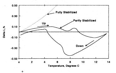
Figure 8.27: ZrO2-MgO, Thermal Expansion. Referring to Figure 8.26, the thermal expansion of B containing both free standing and included tetragonal-monoclinic zirconia produces a thermal expansion with a low value.
Why is there such an odd shape to the curve? The first hump in the curve is due to the freestanding, monoclinic grains transforming to the tetragonal phase. This results in a contraction. The second hump or contraction in the curve to the right denotes the internal, monoclinic inclusions transforming into tetragonal zirconia. Tetragonal grains enclosed in the cubic matrix temporarily restrain them from flipping over to the tetragonal crystal structure. This restraint on increasing the inclusion's volume is responsible for the higher transformation temperature. Overall, the body has a low thermal expansion, which is great for thermal shock resistance. In referring to the list of craft tools, one recalls the sintering temperature. Note, on the phase diagram, that the sintering temperature is lower than that for the first composition. Typically, it is about 1650 °C. At this temperature, zirconia will not fully densify leaving residual porosity. When fully dense, the ceramic produces a high-pitched ring if tapped with
288 Ceramic Technology and Processing
a steel rod. When porous and with a lower modulus, the ceramic produces a flat sound. This is exactly what one needs. The flat sound means that the modulus of elasticity is lower, greatly increasing resistance to thermal shock. The two tools, much lower thermal expansion and lower modulus, enable the ceramic to sustain serious thermal shock for about 20-40 cycles.
Take another look at the phase diagram. It does not take very much MgO to partially stabilize the structure. This makes the ceramic sensitive to chemical changes in composition. For example, when silica is present, it reacts with the MgO, shifting the zirconia composition to the left. Use X- ray diffraction measurements of the ratio of cubic to monoclinic (or tetragonal) to establish a location on the phase diagram. In the example, one can add MgO to correct the composition.
Check List, Zirconia
•Study the phase diagram.
•Select the amount of MgO.
•Establish the firing curve: Binder burnout, Ramp up,
Soak, Anneal, and Ramp down.
•Correct the composition.
•Correct the firing cycle.
Al2O3-glassy bond
These ceramics are commonly used as wear-resistant materials, grinding media, electronic substrates, and jar mills. The microstructure is unique with small (2-4 μm) alumina grains faceted and embedded in a glassy matrix.
Firing 289
Composition. Alumina is present as 85-90% of the composition. Glass is formed by batching in clay, talc, and sometimes CaCO3 or BaCO3. Clays are usually ball clays. The glass formed during firing is an alkaline earth alumina silicate with Na2O picked up from the Bayer Process alumina.
Sintering. Liquid in mass transport also helps densification. This allows a lower temperature (1500-1550 °C or so) for sintering; 1500 °C is cheaper than 1700 °C that may be needed for pure Bayer alumina. Burnout, ramp up, soak, and ramp down are not unusual.
Microstructure. Some regions in the structure are fully dense containing faceted alpha alumina crystals in a small amount of glass matrix. In other regions, there are large pores 10-20 μm in diameter. It is hard to prove, but it is possible that these pores form when the glass coalesces to form an impermeable mass. Then, constituents in the composition continue to degas, resulting in the bubbles that we call porosity. If these speculations are close to being right, then possible solutions could be to soak at a temperature just below that where the gases come off, to substitute non gassing raw materials, or to fire in a vacuum. Dental porcelains are vacuum fired to remove porosity. Vacuum firing is not practical for bulk amounts of a product. Substitution of raw materials could be a more practical solution. Perhaps, it is the ball clay causing the porosity. Ball clay contains all sorts of gas precursors such as water and organic particles. Kaolin eliminates the organic component and calcined kaolin eliminates the water. A few experiments on a degassing soak might be worth considering.
Checklist, Firing alumina/ Glass
•Temperature
•Gas evolution
290 Ceramic Technology and Processing
Recrystallized SiC
SiC is a very tightly, atomically-bonded material that does not shrink when sintered unless additives are included. Whenever the sintering mechanism is either vapor transport or surface diffusion, the ceramic recrystallizes but does not shrink. Strength is higher with higher densities. As it does not densify, it is necessary to obtain a high green density during forming. This is achieved by gap sizing and slip casting.3 Figure 4.29, shown earlier, indicates the general area for obtaining the maximum green density. Casting slips have a high solids content and are dilatant. Deflocculant concentration and pH are both controlled.
As previously mentioned, the kiln is set to a Si-rich atmosphere realized by either siliconizing the furnace, setting in SiC grain, or both. The kiln response determines the shape of the firing curve. A typical case is a curved ramp up to 2200 °C in three hours, a 2-hour soak, and a cooling curve down to 800 °C in less than two hours. The furnace can include a large power supply for a rapid ramp up and a gas circulating system with a heat exchanger for a rapid ramp down.4 Use a vacuum to purge the furnace. Two vacuum stages make the pump down more efficient: a blower and a fore pump. The blower in front of the fore pump makes the fore pump more effective.
Check List, Recrystallized SiC
•High solids slip
•High green density
•Siliconize furnace
•Purging
5.0HOT PRESSING
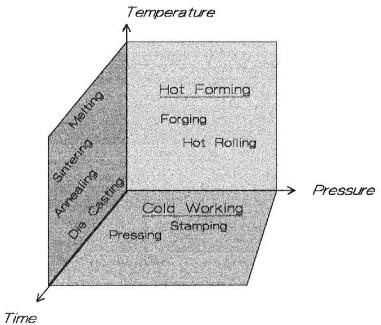
When forming materials, there are three principal, controlling factors: temperature, time, and pressure. Figure 8.28 places some perspective on these parameters.
CLICK TO GO TO NEXT PAGE
Firing 291
Figure 8.28: Forming Methods. On a temperature/pressure/time diagram various forming methods are plotted.
Typical processes are shown in the Figure 8.28. The pressuretemperature plane locates the hot forging and hot rolling processes. Time is a minor factor in this plane. The time/temperature plane locates melting, sintering, die casting, and annealing processes. The pressure/time plane is where the cold working processes appear, such as pressing and stamping. The volume of space is the domain of hot pressing. For ceramics, typical ranges of temperature are from 1300-2700 °C, depending on the ceramic and particle size. Pressures are between 2000-10000 psi and are not strictly
292 Ceramic Technology and Processing
limited to these values. Alumina can be hot pressed from 1400-1700 °C and pressures from 2000-6000 psi in usual cases. With the simultaneous application of both temperature and pressure, the ceramic particles sinter at a higher rate producing a fully dense body at a temperature lower than that used for sintering alone. A finer-grained microstructure is obtained, usually resulting with higher strength and density. While true for most materials, the very high quality, submicron, ceramic powders now available can sinter to structures rivaling those produced by hot pressing.
Hot pressing has the advantage of bypassing some flaws occurring in sintered bodies as the applied pressure overpowers the voids in the ceramic, causing them to collapse. Full density is almost assured for finestarting powders. This is great for ceramic research, but it does not transfer technically to a production sintering process. In these cases where hot pressing is the process of choice, it makes sense to hot press in the lab. Materials that do not sinter readily are candidates for hot pressing. These include refractory carbides, borides, nitrides, some oxides, and composite materials that need a little push to densify. Three subjects: equipment, materials, and procedures will be discussed.
Equipment
Hot presses are electrically heated either by induction or resistance. Commercial equipment is the best choice if one needs a level of sophistication and/or if money is available for purchasing it. Commercial hot presses available for labs are essentially vacuum furnaces with a sealed ram to press on the die.
Induction Heating
An induction furnace was described previously. The hot press differs since the structure has to withstand the stress and to transmit the stress to the die as in Figure 8.29.