

Ceramic Technology and Processing, King
.pdfForming 163
The side port has to include a filter or the mix may end up in the vacuum pump. A wad of cotton works fine when it is stuffed into the side port. When starting to evacuate, the top punch is held above the port. As the vacuum is pulled, the top punch will immediately drop down onto the mix. To fix this, simply tighten a worm gear hose clamp on the top punch against the top of the die body. After removing the air, the clamp is loosened and pressing can begin. For a square die, other types of clamps are effective. A high vacuum is not necessary. All that is required is to remove most of the air, preventing internal air compression sufficient to cause lamination.
Edge relief. This has been mentioned earlier, where a chamfer is ground on the bottom of the die cavity so that spring-back recovery is gradual during stripping. This type of lamination is caused not by air pressure but by mechanical shear stresses.
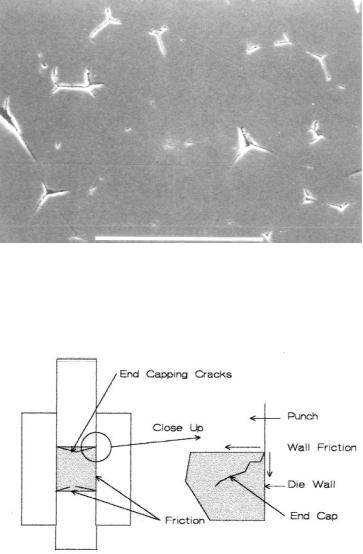
Mix Consistency. For purposes of illustration, consider a spray dried press mix that is being compacted. When the mix is plastic, it will squash together and seal off pockets of air. When the mix is brittle, the granules will fracture and the pressing will remain permeable allowing the air to escape. Depending on the binder system, the plasticity can be adjusted by changing the formulation, often the water content. Some ceramists use bone dry press mixes. Figure 6.19 is of a sintered body where the relic granular structure of the spray dried spheres is evident.
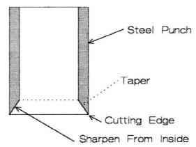
End Capping
This is a crack running in from the top edge of the pressing at an angle to the center, as shown in Figure 6.20.
164 Ceramic Technology and Processing
Figure 6-19: Relict Spray Dried Structure. The spray dried spheres did not coalesce during pressing. Scale bar 100 μm.
Figure 6.20: End Capping. Cracks on the end of the piece are produced during pressing.
Forming 165
There is an analysis by Thompson on end capping.5 It is caused by frictional forces across the punch face and along the die walls. It is also affected by the press mix consistency, with fewer plastic mixes tending to end cap. Decreasing friction between the sample, die, and punch faces can be accomplished by polishing. In the lab, the punch face can be lubricated for each pressing. Try different "lubricants" (the quotes suggest such substances may not necessarily be thought of as lubricants). Stearates can work and are worth a try. In the plant, it would not be practical to lubricate the die for each pressing.
Sticking
Press mixes often stick to the punch faces, causing a reject. Then, before proceeding, the punches have to be cleaned; maybe twice. Solutions to the problem in the lab are not always available in the plant because they can be time-consuming.
Polishing. Polishing the punch faces can help both in the lab and in the plant. A mirror-like, reflective finish is required. The surface will have a minimum area for adhesion, reducing the tendency to stick.
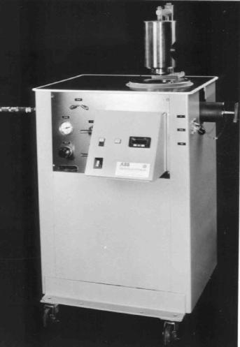
Paper Divider. This is an infallible lab procedure that eliminates sticking. For a round die, a disc of paper is placed on both punch faces to provide a release surface. A paper punch can be made so that the disc fits just right. Make the disc a little undersize so it will go in easily. Figure 6.21 depicts a paper punch design.
Always use the punch on a plastic or wood block. A sharp blow with a mallet will always cut out a perfect disc. In order to preserve the disc diameter, sharpen the cutter by grinding the beveled face.
Release Agents. Some release agents expected to work, fail instead. Silicone release agents do not work well for release. Stearates sometimes work. The best agent for oxides is polyethylene glycol 400 that one applies on the punch faces for each pressing; however, this would be prohibitive
166 Ceramic Technology and Processing
in the plant. A more general approach is to incorporate a release agent in the formulation. Try stearates and try changing the binder or plasticizer.
Figure 6.21: Paper Punch. This punch is useful to cut out precise discs for use in part release.
Hour Glassing
Due to the density gradients in the pressing, the center will have a higher firing shrinkage than the ends. The fired shape resembles an hourglass, or a figure with a waist. When the pressing is single-end pressed, the shape is exaggerated. Hour glassing is a natural consequence of the process. It can be reduced by the following: using a more plastic mix, pressing to a higher pressure, or following pressing with isopressing and green machining. There is additional discussion about this in the chapter on firing.
Warping
Any sporadic difference in green density will result in warping or distortion of the geometry. Warping can also occur when there is a temperature gradient across the piece during firing, where the hot part
Forming 167
sinters more than the cold part. However, the main cause of warping is green density gradients due to an uneven fill. If the kiln has a cold hearth, change it. Raise the hearth so that heat can get under the part as it is firing. The setting technique of the part on the hearth can also cause distortions. This will be discussed in the chapter on firing.
Cracking
Cracks are usually nucleated in pressing. This is usually due to the following factors: shear from uneven cross sections, corners in the die, or differences in thickness. Fine-grained ceramics are also susceptible to thermal shock in firing. The crack is usually formed before the soak. When the crack edges are rounded, the crack is present before sintering. Another factor is that the body is very weak after the binder is burned out. With a very low strength, the part can be easily damaged. Some cracks do not appear on the surface and can only be seen after the part is sectioned. Such cracks are the worst kind as they will become noticeable only after evaluation. The following changes will help eliminate cracks: the tooling geometry, pressing rate, binder/plasticizer, binder strength, pressure reduction, and slowing the temperature rise when firing through the critical region between binder burnout and the start of sintering. In desperation, change the forming method.
Check List, Pressing Problems
•Laminations: bump the press, segmented punch face, vacuum evacuation, stripping edge relief, less plastic mixes
•End Capping: polish the die, less plastic mixes, die lubricants
•Sticking: paper divider, polish the faces, release agents
•Hour glassing: double end press, more plastic mix, higher pressure
•Warping: hot hearth, die design, die fill
•Cracking: die design, even fill, binder/plasticizer, lower pressing rate, stronger binder, slower binder burn change forming method
168 Ceramic Technology and Processing
5.0 OTHER PRESSING TECHNIQUES
Hot pressing and hipping are covered in the chapter on firing. The discussion here is on isopressing.
Isopressing
There are two kinds of isopressing: wet bag and dry bag. In both cases, the press mix is placed in an elastomer bag and compacted with hydraulic pressure on the exterior of the bag. Wet bag isopressing is generally used in the lab as dry bag has dedicated tooling for a particular size and shape.
Wet Bag Isopressing
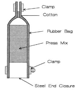
Tooling consists of a rubber bag into which the press mix or preform is placed. The bag is sealed and placed in the isopress. There is a pump that increases the pressure in the press, on the bag, and on the mix; this causes it to compact. Figure 6.22 depicts a photograph of such an isopress.
Features of the isopress are a top closure, a pressure vessel, a diaphragm pump, a fluid storage tank, and a pneumatic lift. The fluid is water with a rust inhibitor. After a bag ruptures by accident, the fluid may become contaminated with ceramic particles that are abrasive and require draining and flushing of the system. Various capacity air pumps are available, with the choice being between speed and cost. For lab work, speed is not too critical.
One makes a rack to hold the samples; this rack is lowered into the cavity. With a loop on top of the rack, it can be snagged with a hook and lifted out of the press. Since shop air may not be clean and dry, it is advisable to filter the air and to add a trap.
After one acquires an isopress, one should choose a large enough ID to adapt to future needs. For general purposes, an ID of between 4" and 6" is about right. Keep in mind that as the volume increases, the pump
Forming 169
capacity also increases by the square of the ID radius. There may be a need for a larger pump.
Figure 6.22: Cold Isopress. Powders or preforms can be uniformly compacted in an isopress. (Courtesy of ABB Autoclave)
170 Ceramic Technology and Processing
One of the principal advantages of isopressing is that the pressing is uniformly compacted, which results in more uniform sintering. Figure 6.23 shows such a typical tooling setup.
Figure 6.23: Isopress Tooling Cylinder. A rubber bag and end closures contain the sample during isopressing.
Basic tooling consists of the following parts: a rubber bag, a base, a clamp, and a wad of cotton. To seal the interior from the liquid, fasten the bag and base with a twisted wire or electrical tape. In the vibrating mode, fill the bag to the base of the neck with press mix. The cotton wad is then pushed down into the neck to prevent aspiration of the mix into the vacuum pump. A vacuum is drawn through the neck and then the mix is sealed with a threaded hose clamp. One can then insert it into the isopress. There are two types of isopress closures: breach block and top plug with a lateral pin. Either closure will do. The plug or breach block is lifted with an air cylinder.
Forming 171
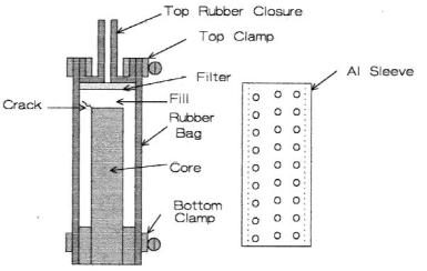
Pressing a closed end tube is a source of unexpected difficulty. The tooling is shown in Figure 6.24.
Figure 6.24: Isopress Tooling, Tube. Pressing around a central rod produces a tube.
The core rod is shown with a square end; however, it is rounded. A square end will always crack at the corner due to shear stresses. The top closure consists of a rubber sleeve with a connecting tube that is folded back on itself. A steel ring provides a structure to clamp against, and another clamp is used to seal the bag when isopressing.
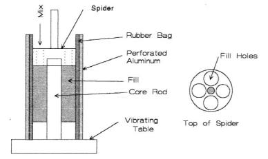
The setup is the same except that there is a central rod to form the ID. Using the same procedure, the tube is pressed at 60,000 psi. When pressing to this high pressure, the rod can bend during the run. Substituting a hardened steel rod, the rod can still bend. The reason for this is obscure. One can circumvent this problem by doing the following: using a spider to center the rod during fill, encasing the bag with a perforated aluminum
172 Ceramic Technology and Processing
cylinder to hold it in shape, and lowering the pressure to 20,000 psi. The setup is sketched in Figure 6.25. The aluminum cylinder is placed around the rubber bag during fill and isopressing.
Figure 6.25: Spider for Centering. The spider centers the core rod for uniform fill. The aluminum cylinder holds the rubber bag in shape.
When there is close control of the firing shrinkage and the mix is pressed around the rod, the center hole in the part is very precise.. The outside diameter of the part is irregular with this tooling and will need to be green machined. Shapes with other cross sections can be made in a similar way. Some rubber companies besides provide sound advice and specialize in making whatever isopress tooling is needed.
Condoms. Unless convenient, it is not necessary to have special tooling to isopress. A pressing can be placed in a condom and simply tied off. It is