

Ceramic Technology and Processing, King
.pdfFiring 233
Bell kilns. Lift the box up to reveal the hearth. As before, there is access to the setting from all sides. Since the hearth is not moved, it is stable. The seal between the bell and the hearth is often a sand seal, at least in larger sizes. For some reason, bell kilns are not common in ceramic laboratories but are common kilns in plants.
Electrical Heating
There are few heating elements for an air atmosphere such as MoSi2, metal, and SiC elements. Metal elements are very dependable but are limited to about 1200-1300 °C. This leaves us with two choices.
SiC. Use of these heating elements is wide spread and has been for a long time. SiC elements are good to about 1550 °C for general use in air. Under certain circumstances, they can be used to 1650 °C. A silica film that forms on the surface of the element inhibits the oxidation of the SiC. During heating and cooling, this film will crack. It will reform during the next heating cycle. However, if the next heating cycle does not reach a high enough temperature to form the film, the SiC will oxidize. Intermediate temperatures of about 600 °C and 1000 °C shorten the life of SiC. One should also remember that resistivity of these elements decreases as the temperature increases. Controls have to adapt to this condition and suitable controls are available.
Electrical contacts and connectors on the ends tend to oxidize, increasing resistance and requiring routine maintenance. There is a problem with the bank of resistors not being in balance. As these get older, the resistivity increases and usually when serviced the old elements are not matched to the newly replaced ones. Some elements run hot and some elements run cold. At worst, one will need to replace the whole bank, and this is expensive. It is important to follow the manufacturer's instructions on the design of the installation. One of these requirements is to leave about 2 inches or 3 inches between the resistor and both the wall and the ware. This helps to avoid hot spots and one is less likely to bump and break the heating element, which is brittle.
234 |
Ceramic Technology and Processing |
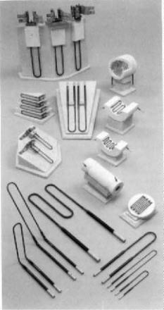
MoSi2. These heaters are wide spread in use. They are good to at least 1600 °C for the regular type. One can extend the temperature to 1900 °C with the super type heaters, but this is pushing it. Use at high temperatures shortens the life of the element, but sometimes this is unavoidable. These elements are available in a variety of sizes and shapes. Figure 8.2 depicts some MoSi2 heating elements.
Figure 8.2: MoSi2 Heating Elements. These elements are available in a variety of sizes and configurations. (Courtesy of Kanthal Corporation, TM).
Firing 235
Try to avoid the smaller diameter elements as they are fragile and warp. As with SiC, a silica film that forms during firing protects the element. When one does not follow the installation instructions, replacing elements can be expensive and the down time extravagant. MoSi2 does not have the problem with resistance change to temperature like SiC, which simplifies the power supply. However, they are very brittle so give them some room to avoid bumping. As with SiC, the elements need clearance from both the refractories and the setting to avoid hot spots. Perhaps the biggest mistake is to buy too small a kiln for general laboratory use. Give the setting and elements some room, and avoid the smallest diameter (3mm) element.
Element life depends on three factors: proper installation, controlled heating and cooling rates, and element bumping. Heating elements are connected in parallel. This increases the amperage of the power supply, but avoids restriction of the element bank by the highestresistance element.
Thermal Insulation
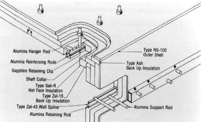
Fiber insulation has been a boon for laboratory kilns. There is a large decrease in thermal mass and an increase in thermal insulation. Fiber refractories are oblivious to thermal shock. With improved electrical heaters and fiber insulation, the ceramist can determine the firing cycle, instead of the kiln's capability. There are several grades of fibers. Differences are largely a matter of the alumina-to-silica ratio. Higher alumina imparts higher temperature capability. However, it is more difficult to blow high alumina fibers, and they are more expensive. They are available in a variety of forms: block, sheets, blankets, paper, bulk, and rope if one needs it. Lab kilns are usually lined with blocks or sheets. Often, pure alumina rods support the fiber blocks especially for the top. Figure 8.3 illustrates the supporting structures.
Type B is especially useful for roofs with larger spans. Hanger rods fastened to the kiln structure hold a hanger body that in turn supports alumina rods and splines. Unless supported, the fiber blocks will sag at high temperatures. Side panels are also supported in a different configuration C as in Figure 8.3.
236 Ceramic Technology and Processing
Figure 8.3: Fiber Block Supports. Rigid fiber panels are supported by alumina rods in the structure. (Courtesy of Zircar, TM)
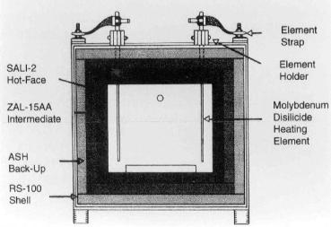
The kiln previously shown in Figure 8.1 has layered insulation as seen in Figure 8.4. Hot face insulation is most critical but, for temperatures above 1600 °C, the fiber block (Zircar SALI (TM)) is currently preferred. Backup insulation consists of an intermediate fiber block with a fiber board against the shell. Note the staggered joints to prevent line-of-sight way for radiation to escape. Again, this is standard practice.
Firing 237
Figure 8.4: Fiber Insulation Structure. Thermal insulation is built up in two or more layers for cost reasons. (Courtesy of Zircar, TM)
Some applications need a hard face when there is a chance for splatters, abrasion, or chemical attack. High alumina refractories are usually a good choice. This type of refractory is not suitable for spanning a distance and the top is an arch, or if one really wants to get fancy, a catenary cross section. If necessary, consult a brick mason as they know the craft.
Traditionally, the backup insulation was fire brick, which comes in several temperature ratings. The higher the temperature rating, the lower its insulating properties. Fiber insulation is becoming almost standard for back up insulation in lab kilns, but not necessarily in production kilns.
Temperature Sensors
The most common temperature sensor is the thermocouple. Most lab kilns use Pt-Pt/Rh thermocouples. At lower temperatures, chromel alumel is very useful because its signal is stronger. It is very important to
238 Ceramic Technology and Processing
calibrate the temperature sensors regularly as measurements can drift into error. Thermocouples are calibrated against an NBS standard, from which one creates secondary standards. One can then use the secondary standard to calibrate the working thermocouples. By placing the working thermocouple close to the secondary standard and making a heating run, the two emfs can provide the data for calibration.
W/Re thermocouples tend to be brittle, but, with time, improvements may rectify this shortcoming. The suppliers of thermocouples have instructions for use that specify temperature settings.
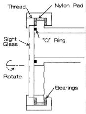
One often uses optical pyrometers, especially at higher temperatures where the limit on thermocouples is exceeded. Two-color pyrometers are preferred. The problem with optics is to keep the sight glass clean. This can be done in two ways: wash it with a gas, or use a sight glass assembly that wipes the glass by rotating an "O" ring wiper that cleans it before the measurement.1 Figure 8.5 shows a sketch of this apparatus.
A gear is built into the rotating mechanism to add a motor to continuously clean the sight glass. It is frustrating to abort a run because the sight glass is fogged up or the sight tube is clogged with deposits. One wastes the entire investment in time and effort when this occurs. To avoid this, put on a self-cleaning sight glass and introduce a gas stream in the tube. This is especially useful for graphite furnaces that when at the desired temperature, exude copious quantities of obscuring materials.
Obviously, the main problem with optics is that they do not function at temperatures below about 700-800 °C. One can use thermocouples for this range and then withdraw them when the optics takes over. Fine tuning of optical pyrometry can get a little complicated when the requirements for temperature control are critical. One can easily avert many of these complications by looking into a black box. All it is, is a refractory block with a hole drilled into it to a depth of about twice the diameter with the temperature reading taken by sighting into the hole. To illustrate this point, read this page illuminated with a halogen light source. The black box eliminates reflections that can mislead an optical pyrometer.
Firing 239
Figure 8.5: Self Cleaning Sight Glass. Rotating the sight glass wipes the "O" ring clean.
Controls
There are many choices of controls. For most uses, the controls are too complicated. One needs a couple of ramps, a soak time at temperature, and a ramp down which often is normal furnace cooling. Whenever the firing cycle is more complicated, a personal computer (PC) is a very good control of choice, but it ordinarily has more capability than needed. It cannot only run the program but can also store the data, analyze the data, signal alarms, store the record, draw graphs, and finally condense a printout. A PC can run a variety of kilns, and they are relatively cheap. A PC is the computer of choice for two reasons: it is less expensive, and there is much more software available. When connected to the appropriate signal conditioners, a PC can do a variety of functions, actuating all kinds of devices.
240 Ceramic Technology and Processing
Hearth
Raise the box kiln hearths to prevent heat from being conducted away from the setting by the hearth plate. A cold hearth will cause uneven sintering. If one has a cold hearth, raise it with an additional refractory plate resting on spacer blocks. These blocks provide an air space under the hearth for hot gas circulation and thermal insulation. The span between the blocks is important, and they should be close enough to resist plate sagging. The hearth plate will still sag a little, but one trick is to put the setting on a bed of coarse refractory grain. If it sags too much, turn it over. Hearth plate materials should be refractory enough, and should be supported enough to resist sagging. Not all alumina are equal, so find one that works. Ask for samples and simply run a sag test by supporting the bar sample over a span and heating to the soak temperature. Measure the sag when cool. Another hearth requirement: it should not react chemically with the setting or the kiln structure. This is highly temperature dependant; Zirconia and alumina are compatible up to 1600 °C. At higher temperatures, alumina will react with stabilized zirconia so one will have to use different setting practices; these will be described in a later section.
Atmospheres
One can use a gasket around the door and a box kiln for firing in other atmospheres, principally nitrogen or argon. Obviously, cool the gasket and securely clamp it to make the seal. When firing in other atmospheres, it is best to evacuate the kiln box and back fill with the gas. Flushing is never complete in a box kiln, especially inside the refractory porosity.
When retrofitting a kiln for atmosphere use, the structure may not be strong enough to support the stresses imposed by the vacuum, in which case the kiln shell will crumple. Remember that gas will expand when heated and pressure will build up. Connect a bubbler to the kiln to avoid this problem. Also remember that the gas will contract as it cools. Never suck water into a hot kiln. A second empty reservoir between the kiln and
Firing 241
the bubbler will catch any back flow. One can purchase atmosphere kilns. Water vapor, CO, CO2, halogens, and hydrogen are harmful to SiC and MoSi2 heating elements. Firing in hydrogen has the additional problem
of being an explosive hazard. Properly designed furnaces are generally safe if maintained. Box kilns are not usually used with hydrogen as they are often not tight enough. An explosion panel is a good idea as it will direct the explosion away from the personnel should the kiln blow up.
Check List, Box Kilns
•Configuration: kiln type and size
•Electrical heating: SiC, Si3N4, installation
•Thermal insulation: fiber
•Temperature sensors: Pt-Pt/Rh, optical, clean sight glass
•Controls: simple, PC
•Hearth: chemically compatible, sag, raised
•Atmosphere: vacuum purging, gas flow control, explosion panel
Tube Furnaces, Air
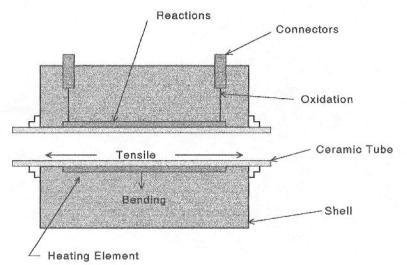
Tube furnaces are usually simple structures with a ceramic tube, a heating element, thermal insulation, and a shell. Most tube furnaces are special purpose furnaces used for a variety of things, some of which will be discussed. It will not be especially helpful to list the furnace types, since these can be obtained from catalogs. Briefly, tubes are made from a variety of materials: dense ceramics, coarse-grained ceramics, fused silica, and metals. Heating elements include: Ni-Cr, Pt, Mo, SiC, MoSi2, and C. The rest of the discussion will focus on problems with air atmosphere, lab-sized tube furnaces, and what to look for when one acquires such a furnace. Figure 8.6 is a simplistic sketch of a typical tube furnace, presented here for reference.
242 Ceramic Technology and Processing
Figure 8.6: Tube Furnace Air Atmosphere. The ceramic tube is subjected to stresses and chemical reactions that can shorten its life.
In the sketch, the tube is subjected to bending stresses if it is not centrally supported. This becomes a little tricky as the conditions at room temperature are different from those at the soak temperature when everything hot expands. Tube failure is usually due to bending stresses at elevated temperatures when the refractory is weak. The worst scenario: when the tube is rigidly supported at the ends and is free to sag in the center. In this case, there are also tensile stresses during cooling, as suggested in the figure, since the kiln structure is cool and does not expand. Figure 8.7 depicts a commercial tube furnace.