

1-6
GENERAL INFORMATION
Oil
Seal, Grease Seal
Do
not remove pressed oil or grease seals unless removal
is
necessary. Replace with new ones whenever removed.
Press
new oil seals with manufacture and size marks facing
out.
Make sure the seal is aligned properly when installing.
Circlips,
Cotter Pins
Replace
circlips or cotter pins that were removed with new
ones.
Install the circlip with its sharp edge facing outward
and
its chamfered side facing inward to prevent the clip from
being
pushed out of its groove when loaded. Take care
not
to open the clip excessively when installing to prevent
deformation.
Lubrication
It
is important to lubricate rotating or sliding parts during
assembly
to minimize wear during initial operation. Lubri-
cation
points are called out throughout this manual, apply
the
specific oil or grease as specified.
Direction
of Engine Rotation
When
rotating the crankshaft by hand, the free play
amount
of rotating direction will affect the adjustment. Ro-
tate
the crankshaft to positive direction (clockwise viewed
from
output side).
http://moto.amoti.ru/
Before Servicing


GENERAL
INFORMATION 1-7
Before
Servicing
Electrical
Wires
A
two-color wire is identified first by the primary color and
then
the stripe color. Unless instructed otherwise, electrical
wires
must be connected to those of the same color.
Y/R
~T\
aJ
<
Oca fe
http://mofo.amofi.rtt/

1-8
GENERAL INFORMATION
ZX636-B1
(Ninja ZX-6R) Left Side View:
ZX636-B1
(Ninja ZX-6R) Right Side View:
G8038080
S
68036081
S
http://mofo.amofi.rtt/


Model Identification
GENERAL
INFORMATION 1-9
ZX600-K1
(Ninja ZX-6RR) Left Side View:
ZX600-K1
(Ninja ZX-6RR) Right Side View:
http://moto.amoti.ru/


Model Identification


Items |
ZX636-B1 (Ninja ZX-6R) |
Dimensions: |
|
Overall length |
2 025 mm (79.7 in.) |
Overall width |
720 mm (28.3 in.) |
Overall height |
1 100 mm (43.3 in.) |
Wheelbase |
1 400 mm (55.1 in.) |
Road clearance |
130 mm (5.1 in.) |
Seat height |
825 mm (32.4 in.) |
Dry mass |
161 kg (1579 N, 355 lb) |
Curb mass: Front |
95 kg (932 N, 209 lb) |
Rear |
93 kg (912 N, 205 lb) |
Fuel tank capacity |
18 L (4.76 US gal) |
Performance: |
|
Minimum turning radius |
3.3 m (10.8 ft) |
Engine: |
|
Type |
4-stroke, DOHC, 4-cylinder |
Cooling system |
Liquid-cooled |
Bore and stroke |
68.0 x 43.8 mm (2.6 x 1.7 in.) |
Displacement |
636 mL (38.8 cu in.) |
Compression ratio |
12.8 |
Maximum horsepower |
87.0 kW (118 PS) @13 000 r/min (rpm), (AU) 84.2 kW (114 PS) @12 000 r/min (rpm), (FR) 78.2 kW (106 PS) @12 500 r/min (rpm), (US), (CAL), (CA) |
Maximum torque |
67.0 N-m (6.8 kgf-m, 49 ft-lb) @11 000 r/min (rpm), (US), (CAL), (CA), (FR) |
Carburetion system |
FI (Fuel Injection), KEIHIN TTK-38 x 4 |
Starting system |
Electric starter |
Ignition system |
Battery and coil (transistorized) |
Timing advance |
Electronically advanced (digital igniter in ECU) |
Ignition timing |
From 12.5: BTDC @1 300 r/min (rpm) to 35' BTDC @4 600 r/min (rpm) |
Spark plug |
NGK CR9E |
Cylinder numbering method |
Left to right, 1-2-3-4 |
Firing order |
1-2-4-3 |
Valve timing: |
|
Inlet Open |
58 BTDC |
Close |
82 ABDC |
Duration |
320* |
Exhaust Open |
62 BBDC |
Close |
34: ATDC |
Duration |
276* |
Lubrication system |
Forced lubrication (wet sump with cooler) |
Items |
ZX636-B1 (Ninja ZX-6R) |
Engine oil: Type |
API SE, SF or SG API SH or SJ with JASO MA |
Viscosity Capacity |
SAE10W-40 4.0 L (4.2 US qt) |
Drive Train: Primary reduction system: Type Reduction ratio Clutch type Transmission: Type Gear ratios: 1st 2nd 3rd 4th 5th 6th Final drive system: Type Reduction ratio Overall drive ratio |
Gear 2.022 (89/44) Wet multi disc 6-speed, constant mesh, return shift 2.923 (38/13) 2.055 (37/18) 1.722 (31/18) 1.450 (29/20) 1.272 (28/22) 1.153 (30/26) Chain drive 2.666 (40/15) 6.223 @Top gear |
Frame: Type Caster (rake angle) Trail Front tire: Type Size Rear tire: Type Size Front suspension: Type Wheel travel Rear suspension: Type Wheel travel Brake Type: Front Rear |
Tubular, diamond 24.5° 95 mm (3.7 in.) Tubeless 120/65 ZR17 M/C (56W) Tubeless 180/55 ZR17 M/C (73W) Telescopic fork (upside-down) 120 mm (4.7 in.) Swingarm (uni-trak) 135 mm (5.3 in.) Dual discs Single disc |
Electrical Equipment: Battery |
12 V 8 Ah |
|
Items |
ZX636-B1 (Ninja ZX-6R) |
Headlight: Type |
|
Semi-sealed beam |
Bulb |
Hi |
12 V 55 W (quartz-halogen) * 2 |
|
Lo |
12 V 55 W (quartz-halogen) |
Tail/brake light |
|
12 V 0.5/3.8 W (LED) |
Alternator: |
Type |
(US), (CAL), (CA) 12 V 0.5/5 W (LED) Three-phase AC |
|
Rated output |
22.5 A /14 V @5 000 r/min (rpm) |
Items |
ZX600-K1 (Ninja ZX-6RR) |
Dimensions: |
|
Overall length |
2 025 mm (79.7 in.) |
Overall width |
720 mm (28.3 in.) |
Overall height |
1 100 mm (43.3 in.) |
Wheelbase |
1 400 mm (55.1 in.) |
Road clearance |
130 mm (5.1 in.) |
Seat height |
825 mm (32.4 in.) |
Dry mass |
161 kg (1579 N, 355 lb) |
Curb mass: Front |
95 kg (932 N, 209 lb) |
Rear |
93 kg (912 N, 205 lb) |
Fuel tank capacity |
18 L (4.76 US gal) |
Performance: |
|
Minimum turning radius |
3.3 m (10.8 ft) |
Engine: |
|
Type |
4-stroke, DOHC, 4-cylinder |
Cooling system |
Liquid-cooled |
Bore and stroke |
67.0 x 42.5 mm (2.6 x 1.7 in.) |
Displacement |
599 mL (36.6 cu in.) |
Compression ratio |
13.0 |
Maximum horsepower |
83.1 kW (113 PS) @13 200 r/min (rpm), (FR) 78.2 kW (106 PS) @13 000 r/min (rpm), (US), (CAL), (CA) |
Maximum torque |
64.4 N m (6.6 kgf-m, 47.5 ft-lb) @12 000 r/min (rpm), (US), (CAL), (CA), (FR) |
Carburetion system |
FI (Fuel Injection), KEIHIN TTK-38 * 4 |
Starting system |
Electric starter |
Ignition system |
Battery and coil (transistorized) |
Timing advance |
Electronically advanced (digital igniter in ECU) |
Ignition timing |
From 12.5 BTDC @1 300 r/min (rpm) to 35: BTDC @4 600 r/min (rpm) |
Spark plug |
NGK CR9E |
Cylinder numbering method |
Left to right, 1-2-3-4 |
Firing order |
1-2-4-3 |
Valve timing: |
|
Inlet Open |
55° BTDC |
Close |
85: ABDC |
Duration |
320= |
Exhaust Open |
62° BBDC |
Close |
34 ATDC |
Duration |
276c |
Lubrication system |
Forced lubrication (wet sump with cooler) |
Items |
ZX600-K1 (Ninja ZX-6RR) |
Engine oil: Type |
API SE, SF or SG API SH or SJ with JASO MA |
Viscosity Capacity |
SAE10W-40 4.0 L (4.2 US qt) |
Drive Train: Primary reduction system: Type Reduction ratio Clutch type Transmission: Type Gear ratios: 1st 2nd 3rd 4th 5th 6th Final drive system: Type Reduction ratio Overall drive ratio |
Gear 2.022 (89/44) Wet multi disc 6-speed, constant mesh, return shift 2.923 (38/13) 2.055 (37/18) 1.722 (31/18) 1.450 (29/20) 1.272 (28/22) 1.153 (30/26) Chain drive 2.666 (40/15) 6.223 @Top gear |
Frame: Type Caster (rake angle) Trail Front tire: Type Size Rear tire: Type Size Front suspension: Type Wheel travel Rear suspension: Type Wheel travel Brake Type: Front Rear |
Tubular, diamond 24.5° 95 mm (3.7 in.) Tubeless 120/65 ZR17 M/C (56W) Tubeless 180/55 ZR17 M/C (73W) Telescopic fork (upside-down) 120 mm (4.7 in.) Swingarm (uni-trak) 135 mm (5.3 in.) Dual discs Single disc |
Electrical Equipment: Battery |
12 V 8 Ah |
|
Items |
ZX600-K1 (Ninja ZX-6RR) |
Headlight: Type |
|
Semi-sealed beam |
Bulb |
Hi |
12 V 55 W (quartz-halogen) * 2 |
|
Lo |
12 V 55 W (quartz-halogen) |
Tail/brake light |
|
12 V 0.5/3.8 W (LED) |
Alternator: |
Type |
(US), (CAL), (CA) 12 V 0.5/5 W (LED) Three-phase AC |
|
Rated output |
22.5 A /14 V @5 000 r/min (rpm) |
Specifications
subject to change without notice, and may not apply to every
country. (US): United States Model (CAL): California Model (CA):
Canada Model (FR): France Model
http://mofo.amofi.rtt/
1-16
GENERAL INFORMATION
Technical
Information - Air Inlet System
Inlet
Duct
Frame
Air
Cleaner Element
Air
Cleaner Housing
Resonator
Air
Duct #1, 4 (Short)
Air
Duct #2, 3 (Long)
Guide
Vane
Center
Ram Air Inlet
The
ram air duct was moved from both left and right side
to
center of the fairing so that incoming air has a straighter
path
to the airbox, increasing ram air efficiency. The duct
was
also designed to maintain optimum airflow despite ex-
treme
changes in bike attitude, such as during hard accel-
eration,
braking, and cornering. With fewer parts and the
duct
also acting as the instrument, the new system also cuts
weight.
http://moto.amoti.ru/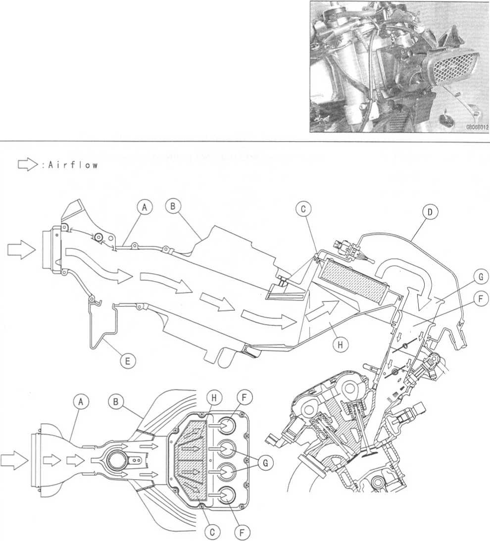
GENERAL
INFORMATION 1-17
Technical
Information - Air Inlet System
Subthrottle
Control System
The
ZX636-B1 and ZX600-K1 utilize large bore throttle bodies to increase
power output. However, sudden changes in throttle opening can cause
hesitation and jerky throttle response with a single butterfly valve
in a large bore. Therefore two throttle valves are placed in each
inlet tract, the main throttle valve located closest to the cylinder
and a subthrottle valve placed further up the inlet tract. The main
throttle valve is operated by the rider when the throttle grip is
turned, while the subthrottle valve is operated by a stepping motor
controlled by the ECU. The subthrottle valve automatically adjusts
air inlet to more precisely match engine demand, so that when the
main throttle is opened quickly there is no hesitation or jerky
response.
The
subthrottle valves allow the fuel injection system to provide smooth
throttle response, similar to that of a constant velocity
carburetor, no matter how quickly the throttle is opened.
Main
Throttle Valve
Subthrottle
Valve
Throttle
Valve
Vacuum
Piston
Inlet
Air
hftp://mofo.amofi.ru/
1-18
GENERAL INFORMATION Technical Information - Air Inlet System
Operation
The
subthrottle control system consists of the subthrottle valve,
subthrottle valve actuator with a stepping motor built in it, ECU,
and subthrottle sensor. The subthrottle valve is built in the each
throttle body.
The
subthrottle control system operates on the signal supplied from the
ECU. The open/close operation of the subthrottle valve is
performed by the subthrottle actuator which is controlled by the ECU
to change the current direction into the motor of the subthrottle
valve actuator.
The
subthrottle sensor detects the subthrottle valve actuator movement
by measuring voltage and the ECU determines the subthrottle valve
angle based on the operation map.
When
turning the ignition switch ON, every time the ECU automatically
drives the subthrottle valve from fully closed position to fully
opened position. The ECU memorizes these positions and turns back
the subthrottle valve to the original point to confirm the
subthrottle valve idling voltage.
Subthrottle
Sensor
Main
Throttle Sensor
Crankshaft
Sensor
Speed
Sensor
http://moto.amoti.ru/
|
Side Stand |
Gear Position |
Clutch Lever |
Engine Start |
Engine Run |
A |
Up |
Neutral |
Released |
Starts |
Continue running |
B |
Up |
Neutral |
Pulled in |
Starts |
Continue running |
C |
Up |
In Gear |
Released |
Doesn’t start |
Continue running |
D |
Up |
In Gear |
Pulled in |
Starts |
Continue running |
E |
Down |
Neutral |
Released |
Starts |
Continue running |
F |
Down |
Neutral |
Pulled in |
Starts |
Continue running |
G |
Down |
In Gear |
Released |
Doesn’t start |
Stops |
H |
Down |
In Gear |
Pulled in |
Doesn’t start |
Stops |
Current
Ignition Interlock Sidestand System |
Side Stand |
Gear Position |
Clutch Lever |
Engine Start |
Engine Run |
A |
Up |
Neutral |
Released |
Starts |
Continue running |
B |
Up |
Neutral |
Pulled in |
Starts |
Continue running |
C |
Up |
In Gear |
Released |
Doesn’t start |
Continue running |
D |
Up |
In Gear |
Pulled in |
Starts |
Continue running |
E |
Down |
Neutral |
Released |
Starts |
Continue running |
F |
Down |
Neutral |
Pulled in |
Starts |
Continue running |
G |
Down |
In Gear |
Released |
Doesn’t start |
Stops |
H |
Down |
In Gear |
Pulled in |
Start |
Continue running |
http://moto.amoti.ru/
1-20
GENERAL INFORMATION
Technical
Information - Tail/Brake Lights Employing LED
Outline
This
model employs a tail/brake light containing 21 Light Emitting Diodes
(LED). The LED emits luminous beams over a longer life span than
those emitted from a traditional electric heated bulb (more than 5
times longer), uses lower voltage, expends lower wattage
(approx.1/5), and is quicker responsing.
Due
Position of LED Installation
The
resistors, the diodes, and the Zener diodes are
mounted
in the electronic circuits [A] of the LED, which
supplies
the steady current and voltage to the light.
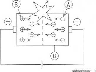
Light
Emitting Diode (LED)
The
Light Emitting Diode (LED) [A] is an element of semi-
conductor
diode that converts applied voltage to light.
The
LED emits luminous beams by the collision of nega-
tive
charge electrons [A] and positive charge holes [B] when
applied
the forward voltage and current to the PN junction
diode
[C],
http://moto.amoti.ru/

Materials of Semi-Conductor |
Emitting Color |
GaAsP, GaAIAs |
Red |
GaP |
Green |
GaN |
Blue |
Ga:
Gallium As: Arsenic
P:
Phosphorus N: Nitrogen Al: Aluminum
http://mofo.amofi.rtt/
1-22
GENERAL INFORMATION
Technical
Information - KAWASAKI LOW EXHAUST EMISSION SYSTEM
Since
the emission regulations become more severe, Kawasaki has adopted a
type of simplified KAWASAKI LOW EXHAUST EMISSION SYSTEM (KLEEN),
which have no catalyst protection system, according to each
regulation of different countries.
The
muffler with built-in catalyst has the same durability as the
conventional muffler, however, do not use leaded gasoline and do not
coast with the ignition system OFF. Running the engine without
ignition damages catalyst.
Refer
to the ZX636A Service Manual (Part No. 99924-1288) for more
information about the KLEEN (theory, maintenance, and handling
precautions), including the secondary air injection system.
Honeycomb
Type Catalytic Converter
oThe
converter is a three-way catalytic converter, and its surface is
covered with alumina upon which platinum and rhodium are applied,
and has a cylindrical metallic honeycomb structure made by bending a
corrugated sheet and a flat sheet of stainless steel into a spiral
of increasing diameter. The honeycomb structure is convenient for
the catalytic converter because it has a large surface area but
small size to react effectively and has low exhaust resistance. In
addition, its inherent strength helps resist vibration, and has
simple structure welded directly on the silencer.
O
Generally, the temperature of the exhaust gas must be higher than
activation temperature, so the converters are installed in the
exhaust manifold rear end where the temperature of exhaust gas is
still high. And, the converters will be activated even under low
load conditions.
O
After the exhaust gas is diluted with the secondary air injection,
the catalytic converter works well because of rich oxygen to reduce
CO, HC, and NOx. Accordingly, we can keep the exhaust gas emission
within regulation.
OThis
type of converter works more efficiently as a three-way catalytic
converter to reduce CO, HC, and NOx than the pipe type catalytic
converter because of its more and denser catalysts.
Manifold
Silencer
Honeycomb
Type Catalyst
Non-Catalyst
(Pipe Type)
Mark
for Manifold
Mark
for Silencer
http://moto.amoti.rtt/
Unit Conversion Table |
||||||
Prefixes for Units: |
|
Units of Length: |
||||
|
Prefix |
Symbol |
Power |
km |
x 0.6214 = mile |
|
|
mega |
M |
|
x 1 000 000 |
m |
x 3.281 = ft |
|
kilo |
k |
|
x 1 000 |
mm |
x 0.03937 = in |
|
centi |
c |
|
x 0.01 |
|
|
|
milli |
m |
|
x 0.001 |
|
|
|
micro |
P |
|
x 0.000001 |
Units of Torque: |
|
|
|
|
|
N-m |
x 0.1020 = kgf-m |
|
|
|
|
|
N-m |
x 0.7376 = ft-lb |
|
Units of Mass: |
|
|
N-m |
x 8.851 = in-lb |
||
kg x |
2.205 |
= lb |
kgf-m |
x 9.807 = N-m |
||
9 x |
0.03527 |
= oz |
kgf-m |
x 7.233 = ft-lb |
||
|
|
|
|
kgf-m |
x 86.80 = in-lb |
|
Units of Volume |
|
|
|
|
||
L x |
0.2642 |
= gal (US) |
Units of Pressure: |
|||
L x |
0.2200 |
= gal (imp) |
kPa |
x 0.01020 = kgf/cm2 |
||
L x |
1.057 |
= qt (US) |
kPa |
x 0.1450 = psi |
||
L x |
0.8799 |
= qt (imp) |
kPa |
x 0.7501 = cm Hg |
||
L x |
2.113 |
= pint (US) |
kgf/cm2 |
x 98.07 = kPa |
||
L x |
1.816 |
= pint (imp) |
kgf/cm2 |
X 14.22 = psi |
||
mL x |
0.03381 |
= oz (US) |
cm Hg |
x 1.333 = kPa |
||
mL x |
0.02816 |
= oz (imp) |
|
|
||
mL x |
0.06102 |
= cu in |
|
|
||
|
|
|
|
Units of Speed: |
||
|
|
|
|
km/h |
x 0.6214 = mph |
|
Units of Force: |
|
|
|
|
||
N x |
0.1020 |
= kg |
|
|
||
N x |
0.2248 |
= lb |
Units of Power: |
|||
kg x |
9.807 |
= N |
kW |
x 1.360 = PS |
||
kg x |
2.205 |
= lb |
kW |
x 1.341 = HP |
||
|
|
|
|
PS |
x 0.7355 = kW |
|
|
|
|
|
PS |
x 0.9863 = HP |
|
Units of Temperature: |
|
|
|
|||
9 ("C + 4 0) 5 |
- 40 |
= °F |
5 (°F +40) 9 |
40 = °C |
||
°F |
|
|
|
|
° F |
|
-4 |
32 |
68 104 |
176 212 248 284 |
|||
-40 -20 i I I_4 |
0 20 J J-. |
40 u±. ... |
60 i 80 100 i 120 I I 1 , lj I |
140 160 =180 200 I I U I |
220 240 j 260 280 i 300 320 L 1=1 li i i |
|
I I I -40 -20 |
f ! ( |
|
i n 1 r 20 •' 40 ! |
l M l I I ! I I I 60 ! 80 : 100 - 120 = 140 ifin |
||
- |
17.8 |
4.4 |
26.7 48.9 |
71.1 93.3 |
116 138 |
|
°C |
|
|
|
|
°C |
|