

Text 7. Optical telegraph
T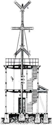 he
first telegraphs came in the form of optical
telegraph including
the use of smoke
signals, beacons
or reflected
light, which have
existed since ancient times. A semaphore
network invented by
Claude
Chappe operated in
France from 1792 through 1846. It helped Napoleon
enough to be widely imitated in Europe and the U.S. In the
Peninsular
War (1807–1814),
several similar telegraphs had been used in the Lines
of Torres Vedras, by
the Anglo-Portuguese army. The Prussian
system was put into
effect in the 1830s. The last commercial semaphore link ceased
operation in Sweden in 1880.
he
first telegraphs came in the form of optical
telegraph including
the use of smoke
signals, beacons
or reflected
light, which have
existed since ancient times. A semaphore
network invented by
Claude
Chappe operated in
France from 1792 through 1846. It helped Napoleon
enough to be widely imitated in Europe and the U.S. In the
Peninsular
War (1807–1814),
several similar telegraphs had been used in the Lines
of Torres Vedras, by
the Anglo-Portuguese army. The Prussian
system was put into
effect in the 1830s. The last commercial semaphore link ceased
operation in Sweden in 1880.
Semaphores were able to convey information more precisely than smoke signals and beacons, and consumed no fuel. Messages could be sent at much greater speed than post riders and could serve entire regions. However, like beacons, smoke and reflected light signals they were highly dependent on good weather and daylight to work (practical electrical lighting was not available until about 1880). They required operators and towers every 30 km (20 mi), and could only accommodate about two words per minute. This was useful to governments, but too expensive for most commercial uses other than commodity price information. Electric telegraphs were to reduce the cost of sending a message thirtyfold compared to semaphores, and could be utilized non-stop, 24 hours per day, independent of the weather or daylight.
Elevated locations where optical telegraphs were placed for maximum visibility were renamed to Telegraph Hill, such as Telegraph Hill, San Francisco, and Telegraph Hill in the PNC Bank Arts Center in New Jersey.
Text 8. E-mail displaces telegraphy
E-mail was first invented for CTSS and similar time sharing systems of the era in the mid-1960s. At first, e-mail was possible only between different accounts on the same computer (typically a mainframe). ARPANET allowed different computers to be connected to allow e-mails to be relayed from computer to computer, with the first ARPANET e-mail being sent in 1971. Multics also pioneered instant messaging between computer users in the mid-1970s. With the growth of the Internet, e-mail began to be possible between any two computers with access to the Internet. This led to the development of a form of communication that is a hybrid between a telegram and an email, namely the Edigram. Such communications could be sent on a round-the-clock basis, and were characterized as being short, concise and lacking any superfluous terms.
Various private networks like UUNET (founded 1987), the Well (1985), and GEnie (1985) had e-mail from the 1970s, but subscriptions were quite expensive for an individual, US$25 to US$50 per month, just for e-mail. Internet use was then largely limited to government, academia and other government contractors until the net was opened to commercial use in the 1980s.
By the early 1990s, modems made e-mail a viable alternative to Telex systems in a business environment. But individual e-mail accounts were not widely available until local Internet service providers were in place, although demand grew rapidly, as e-mail was seen as the Internet's killer app. It allowed anyone to email anyone, whereas previously, different system had been walled off from each other, such that America Online subscribers could only email other America Online subscribers, Compuserve subscribers could only email other Compuserve subscribers, etc. The broad user base created by the demand for e-mail smoothed the way for the rapid acceptance of the World Wide Web in the mid-1990s. Fax machines were another technology that helped displace the telegram.
On Monday, 12 July 1999, a final telegram was sent from the National Liberty Ship Memorial, the SS Jeremiah O'Brien, in San Francisco Bay to President Bill Clinton in the White House. Officials of Globe Wireless reported that "The message was 95 words, and it took six or eight minutes to copy it." They then transmitted the message to the White House via e-mail. That event was also used to mark the final commercial U.S. ship-to-shore telegraph message transmitted from North America by Globe Wireless, a company founded in 1911. Sent from its wireless station at Half Moon Bay, California, the sign-off message was a repeat of Samuel F. B. Morse's message 155 years earlier, "What hath God wrought?"
1. Tom Van Vleck. "The History of Electronic Mail"
2. Samuel F. B. Morse, Examination of the Telegraphic Apparatus and the Processes in Telegraphy, pages 7-8, Philp & Solomons 1869 OCLC 769828711
Text 9. History of television. Part -1
I
 n
its early stages of development, television employed a combination
of optical,
mechanical and electronic
technologies to capture, transmit and display a visual image. By the
late 1920s, however, those employing only optical and electronic
technologies were being explored. All modern television systems
relied on the latter, although the knowledge gained from the work on
electromechanical systems was crucial in the development of fully
electronic television.
n
its early stages of development, television employed a combination
of optical,
mechanical and electronic
technologies to capture, transmit and display a visual image. By the
late 1920s, however, those employing only optical and electronic
technologies were being explored. All modern television systems
relied on the latter, although the knowledge gained from the work on
electromechanical systems was crucial in the development of fully
electronic television.
The first images transmitted electrically were sent by early mechanical fax machines, including the pantelegraph, developed in the late nineteenth century. The concept of electrically powered transmission of television images in motion was first sketched in 1878 as the telephonoscope, shortly after the invention of the telephone. At the time, it was imagined by early science fiction authors, that someday that light could be transmitted over copper wires, as sounds were.
The idea of using scanning to transmit images was put to actual practical use in 1881 in the pantelegraph, through the use of a pendulum-based scanning mechanism. From this period forward, scanning in one form or another has been used in nearly every image transmission technology to date, including television. This is the concept of "rasterization", the process of converting a visual image into a stream of electrical pulses.
I
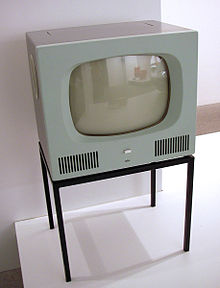
Braun
HF 1 television receiver, Germany, 1958
Text 10. History of television Part -2
Using a Nipkow disk, Scottish inventor John Logie Baird succeeded in demonstrating the transmission of moving silhouette images in London in 1925, and of moving, monochromatic images in 1926. Baird's scanning disk produced an image of 30 lines resolution, just enough to discern a human face, from a double spiral of Photographic lenses. This demonstration by Baird is generally agreed to be the world's first true demonstration of television, albeit a mechanical form of television no longer in use. Remarkably, in 1927 Baird also invented the world's first video recording system, "Phonovision": by modulating the output signal of his TV camera down to the audio range, he was able to capture the signal on a 10-inch wax audio disc using conventional audio recording technology. A handful of Baird's 'Phonovision' recordings survive and these were finally decoded and rendered into viewable images in the 1990s using modern digital signal-processing technology.
In 1926, Hungarian engineer Kálmán Tihanyi designed a television system utilizing fully electronic scanning and display elements, and employing the principle of "charge storage" within the scanning (or "camera") tube.
On December 25, 1926, Kenjiro Takayanagi demonstrated a television system with a 40-line resolution that employed a CRT display at Hamamatsu Industrial High School in Japan. This was the first working example of a fully electronic television receiver. Takayanagi did not apply for a patent.
By 1927, Russian inventor Léon Theremin developed a mirror-drum-based television system which used interlacing to achieve an image resolution of 100 lines.
In 1927, Philo Farnsworth made the world's first working televison system with electronic scanning of both the pickup and display devices, which he first demonstrated to the press on 1 September 1928.
WRGB claims to be the world's oldest television station, tracing its roots to an experimental station founded on January 13, 1928, broadcasting from the General Electric factory in Schenectady, NY, under the call letters W2XB. It was popularly known as "WGY Television" after its sister radio station. Later in 1928, General Electric started a second facility, this one in New York City, which had the call letters W2XBS, and which today is known as WNBC. The two stations were experimental in nature and had no regular programming, as receivers were operated by engineers within the company. The image of a Felix the Cat doll, rotating on a turntable, was broadcast for 2 hours every day for several years, as new technology was being tested by the engineers.
Mexican inventor Guillermo González Camarena also played an important role in early television. His experiments with television (known as telectroescopía at first) began in 1931 and led to a patent for the "trichromatic field sequential system" color television in 1940.
Although television became more familiar in the United States with the general public at the 1939 World's Fair, the outbreak of World War II prevented it from being manufactured on a large scale until after the end of the war. True regular commercial television network programming did not begin in the U.S. until 1948. During that year, legendary conductor Arturo Toscanini made his first of ten TV appearances conducting the NBC Symphony Orchestra, and Texaco Star Theater, starring comedian Milton Berle, became television's first gigantic hit show. Since the 1950s, television has been the main medium for molding public opinion.
Amateur television (ham TV or ATV) was developed for non-commercial experimentation, pleasure and public service events by amateur radio operators. Ham TV stations were on the air in many cities before commercial TV stations came on the air.
In 2012, it was reported that television was growing into a larger component of major media companies' revenues than film.
Text 11. Production of Three-Phase Currents
In an ordinary a.c. circuit the current through all its phases in succession, but at any particular instant the current has only one phase. In the three-phase system there are three circuits, and the currents in these have three different phases at the same instant of time. The phase difference between any two of these three phases is 120.
Imagine an armature core to be rotated in a counter-clockwise direction between the two poles of a magnetic field excited by D. C., as shown in Fig. 5. The two conductors A and A“ are connected in series to form a turn, the front end of the conductor A being considered as the front end of the turn, and the front end conductor A”being considered as the rear end. As the armature core is rotated, a sinusoidal e. m. f. is induced in the turn AA”. Next consider the turn BB”, where B is regarded As the front end and B” the rear end. A sinusoidal e. m. f. will also be induced in this turn, but it does not reach its maximum value in the positive direction until the core has been rotated through 120. In other words, this e. m. f. although having the same maximum and r. m. s. value as induced in the turn AA”, is behind it in phase by 120. Finally, consider the turn CC” in the same way. The induced e. m. f. again has the same maximum and r. m. s. value, but it is a further 120 behind in phase. Following on this, wet another 120 behind in phase,the first turn AA” induces an e. m. f. which is 3X120=360 behind the original e. m. f. induced in AA”. Putting this another way, the turn AA” is now beginning to induce the second cycle of e.m.f. The three e.m.f.”s induced in the three turns are represented graphically in Fig. 6, where it is seen that there is a phase difference of 120, or one third of a cycle, between the e.m.f.”s of each pair. If each of these turns is connected to the ends of a resistance, there currents will be obtained, also having a mutual phase difference of 120, these currents being called three-phase currents.
In practice it is usual to arrange the armature conductors on the stationary element of the machine, now called the stator, the d.c. excited field forming the rotating element, or rotor. Each winding also is made to consist of many turns. It does not matter, however, whether the conductors cut the magnetic flux, or the magnetic flux cuts the conductors; the action is the same.
Text 12. The Telephones
The telephones are connected in series with the detector.
A brief explanation of how the telephone works. Is here necessary. The sensation of sound is excited in the ear by the motion imparted to the air by vibrating bodies. If a flat steel spring be fixed in a vertical position in a vice, and the free end of it be displaced, on releasing it a vibratory motion will follow. The free end will pass backwards and forwards along a gradually decreasing arc. During its first movement to the right, it compresses the air on its right- hand side, and causes a state of rarefaction on its left-hand side. A revers movement has exactly the opposite effect. As long as the spring continues to vibrate, waves of rarefaction and compression are propagated, the frequency of these waves or the number of complete vibrations per second determining whether they are audible or not. It the frequency be anything between 30 and 20,000 per second, audible sounds are produced. The telephone is an instrument capable of producing waves in the air of such a frequency . A disc of thin soft iron, varnished to prevent rusting, takes the palace of the spring just described, and it is set in vibration by fluctuations in the intensity of a magnetic field. Fig. I shows an electro – magnet with its two poles in close proximity to a disc of soft iron D, which is firmly clamped in position by its edges. The core of the magnet is permanently magnetized and exercises a force of attraction on the disc. If a current be passed through the coils wound round its pole pieces, this force of attraction is increased or decreased according to the direction of the current. It the force be increased, the centre ofthe disc is pulled towards the magnet : and if the force be decreased, it is released to some extend . If, then, rapid alternations of current, or intermittent unidirectional currents, be passed through the windings, the disc or “ diaphragm ”, as it is called, is caused to vibrate ; and if the frequency of the vibrations be within the limits stated above, they will produce the sensation of sound in the ear.
On account of its shape the telephone receiver used in a wireless installation is called a “watch” receiver.
Two complete watch receivers are connected in series at the ends of a steel or aluminium strip spring, to form the telephone head-gear . As the space available is very small, the wire used in the coils of the electro-magnets must of necessity by very thin, in order to obtain the necessary ampere-turns required for the high degree of sensitiveness of the telephone. In low resistance telephones the wire is insulated with silk, but where a much greater number of turns is required, as in the case of telephones of from two to eight thousand ohms resistance used with a valve or crystal receiver , the wire insulation usually consists of a coating of enamel, as space is thus economized. In the high resistance telephone a pair of protective spark points is often included, as a guard for the coil windings against excess voltage due either to direct application , inductive kick on suddenly breaking circuit, or high –frequency surge – all tending to damage the insulation. Again, where enamelled wire is used , the interior of case is filled with paraffin wax, further to ensure good insulation and prevent moisture from reaching the windings.
Text 13. Radio waves
Electrical energy that has escaped into free space exists in the form of electromagnetic waves. These waves, which are commonly called radio waves, travel witch the velocity of light and consist of magnetic and electrostatic fields at right angles to each other and also at right angles to the direction of travel.
One half of the electrical energy contained in the wave exists in the form of electrostatic energy, while the remaining half is in the form of magnetic energy.
The essential properties of a radio wave are the frequency, intensity, direction of travel, and plane of polarization. The radio waves produced by an alternating current will vary in intensity witch the frequency of the current and will therefore be alternately positive and negative.
The distance occupied by one complete cycle of such an alternating wave is equal to the velocity of the wave divided by the number of cycles that are sent out each second and is called the wave length.
The relation between wave length in meters and frequency in cycles per second is therefore.
The quantity 300 000 000 is the velocity of light in meters per second. The frequency is ordinaliry expressed in kilocycles, abbreviated KC; or in megacycles, abbreviated MC. A low-frequency wave has a long wave length while a high frequency corresponds to a short wave length.
The strength of a radio wave is measured in terms of the voltage stress produced in space by the electrostatic field of the wave and is usually expressed in microvolts stress per meter.
Since the actual stress produced at any point by an alternating wave varies sinusoidally from instant to instant, it is customary to consider the intensity of such a wave to be the effective value of the stress, which is 0.707 times the maximum stress in the atmosphere during the cycle. The strength of the wave measured in terms of microvolts per meter of stress in space is exactly the same voltage that the magnetic flux of the wave induces in a conductor I meter long when sweeping across this conductor with the velocity of light.
Thus the strength of a wave is not only the dielectric stress produced in space by the electrostatic field, but it also represents the voltage that the magnetic field of the wave will induce in cutting across a conductor.
In fact, the voltage stress produced by the wave can be considered as resulting from the movement of the magnetic flux of the same wave.
The minimum field strength required to give satisfactory reception of a wave depends upon a number of factors, such as frequency, type of signal involved, and amount of interference present. Under some conditions radio waves having signal strengths as low as 5.000 to 30.000 per meter are required to ensure entirely satisfactory reception at all times.
In most cases the weakest useful signal strength lies somewhere between these extremes.
A plane parallel to the mutually perpendicular lines of electrostatic and electromagnetic flux is called the wave front.
The wave always travels in a direction at right angles to the wave front, but whether it goes forward or electromagnetic and electrostatic flux.
If the direction of either the magnetic or electrostatic flux is reversed, the direction of travel is reversed; but reversing both sets of flux has effect.
The direction of the electrostatic lines of flux is called the direction of polarization of the wave. If the electrostatic flux lines are vertical the wave is vertically polarized; when the electrostatic flux lines are horizontal and the electromagnetic flux lines are vertical. The wave is horizontally polarized.
Text 14. Current Transformers
Why Current Transformers are Used.-A current transformer is an instrument transformer for the transformation of current from one value to another,usually a lower one, or for the transformation of current at a high voltage into a proportionate current at a low voltage with respect to earth potential. Current transformers are used in conjunction with alternating-current meters or instruments where the current to be measured is of such magnitude that the meter or instrument current coil cannot conveniently be made of sufficient carrying capacity. They are also used wherever high-voltage current has to be metered,because of the difficulty of providing adequate insulation in the meter itself. In this connection supply voltages exceeding 660 volts are considered to be high voltage. In meter practice current transformers are used wherever the current to be metered exceeds 100 amperes, and in some instances a lower value then this is regarded as the desirable maximum for direct measurement.
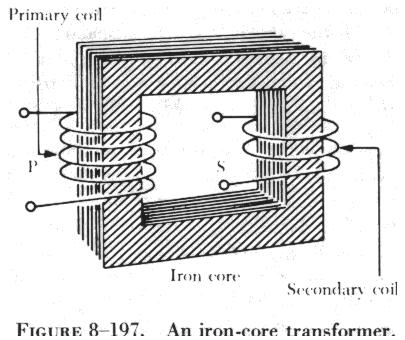
Construction of Current transformers.-A current transformer comprises a magnetic circuit, usually in the form of iron stampings assembled together to form a core, on which are wound two electric circuits called the primary winding and secondary winding respectively. The primary winding carries the current to be measured and is connected in the main circuit. The secondary winding carries a current proportional to the current to be measured and the secondary terminals are connected to the current winding of the meter or instrument: Both windings are insulated from the core and from each other. The secondary insulation is arranged to withstand a test pressure of 2,000 volts applied between the winding and the core for one minute. The insulation of the primary and secondary windings approximately equal to four times the voltage existing under working conditions. During this test the core and the secondary winding are connected together.
The
primary circuit of a current transformer may consist of a single
conductor in the form of a bar or cable instead of s winding, when
the current to be measured is of the order of 600 amperes or more.
In low-voltage circuits the current to be measured may be so heavy
that it is not convenient to provide a primary integral with the
transformer * and the latter then consists of an iron core of
appropriate shape with secondary winding thereon, the whole being
mounted on the busbar or cable. The nominal full-load current of a
transformer is termed the “rated primary current” and is the
value in amperes of the primary current marked on the rating plate.
The secondary winding of a current transformer is usually constructed to deliver five amperes to the meter or instrument when rated primary current flows in the main circuit. This is referred to as the “rated secondary current” and five amperes is the standard value adopted in the most countries. In power-station practice it is not unusual for the meter to be separated from its current transformers by a distance of several hundred feet. The LR loss in the connecting leads together with the loss in the meter current coils may impose a burden in excess of the transformer rating if a five-ampere secondary current the loss in the leads can be substantially reduced and one ampere or 0.5 ampere values are permissible alternatives. Since the loss varies as the square of the current the adoption of one of these alternatives will reduce the loss in the leads to one-twenty-fifths or one-hundredth of the original value respectively.
The magnetic and electric circuits of a current transformer are represented diagrammatically in Fig. 14; the primary winding is shown surrounding one limb of the core and the secondary winding surrounding another. In actual practice the two windings would not be separated in this manner as the primary would be superimposed on the secondary, but they are shown thus for the sake of** clarity in the diagram. The primary terminals by the same letters enclosed in a circle. The cores of current transformers are usually built up with laminations of silicon-steel but where a high degree of accuracy is desired a high-permeability nickel-steel such as Mumetal or Permalloy may be used. Three types of magnetic circuit are in common use, namely, “ring-type”, “core-type”, and “shell-type” and are illustrated in Fig.8.
Text 15. Powerhouse auxiliary motors
A complete description of the many and varied motor applications found in modern steam station is almost the description of the station itself. Every phase of power generation requires some closely associated auxiliary equipment, which, in a modern power plant, id driven almost exclusively by electric motors. Indicative of the large number of water applications in the steam stations, a resent power plant comprising two 75,000-kw turbines required over 700 auxiliary motors. In a typical plant the auxiliaries consume approximately 6 percent of the total power output and have a total horsepower rating of from 12 to 15 percent of the kilowatt rating of the main turbine generations.
No two generating stations are identical. It is impossible to state exactly the motor size and types that will be present in a steam generating station of the particular size. The requirements are governed by such factors as type of fuel, heat cycle, source of water, and anticipated station loading cycle.
Approximate size of the major auxiliary motors are given later as percentages of the nominal rating of the turbine-generator unit. The figures are average values based on a survey of steam stations with turbine-generator units of 100 megawatts and bellow.
Characteristics of Powerhouse Auxiliary Motors.- The primary characteristics to be considered in selecting auxiliary motors are size, speed, motor type, torque requirements, operating conditions, class of insulation, and type on enclosure. In addition, motors for central-station service must have special features that insure reliability and ease of operation, features such as special moisture-resistant insulation, adequate provision for oil0ring inspection on motors with sleeve bearings, easy accessibility of the bearings and windings for servicing and inspection, and adequate terminal boxes. The reliability, efficiency, and simplicity of installation and control of the squirrel-cage indication motor have made it the almost universal choice for powerhouse applications.
Powerhouse auxiliary motors range in size from less than one horse power, used to open and close valves, to several thousand horsepower, used to pump water into the boiler. They usually have drip-proof enclosures with class A insulation, and are designed to have low starting current and normal starting torque. However, some auxiliary require special torque or speed characteristics, or present unusual service conditions such as excessive dirt, moisture, abrasive flyash, or high temperature; or the plant may be an outdoor installation. Motors for such applications must have special characteristics to satisfy these requirements.
Text № 16. Pump Motors
Pumping is one of the major duties performed by powerhouse auxiliary equipment, and usually the largest motors in the station are those that drive the boiler-feed-pumps. In a typical station the total horsepower rating of the boiler-feed-pump motors is between five and six percent of the kilowatt rating of the associates turbine. At least two and usually three boiler-feed pumps of equal rating are used. These pumps operate against a very high head of water and require 3,600-rpm driving motors.
The output of the boiler-feed pumps is controlled by throttling or by varying the speed of the pump. The latter method is attractive because of reduced operating cost. Variable-speed control, when used, is achieved with a variable-speed coupling or by using a wound-rotor motor and a liquid rheostat.
The torque requirements of boiler-feed pumps and most of other pumps are satisfied by motors with low starting current and normal starting torque. Most boiler-feed pump motors are rated for a temperature rise of 40 degrees C above ambient and have class A insulation. Where the ambient temperature is above 40 degrees, class B insulation is used.
Although drip-proof construction is usual, special enclosures are sometimes use to reduce the noise level of the motor or to protect the motor from flyash and other unfavorable atmospheric conditions. Noise can be reduces by using pipe-or base-ventilated motors in which the inlet and exhaust for cooled by air-to-air at a remote location. In particularly dirty locations enclosed motors are used. Air for such motors is cooled by either an air-to-air or an air-to-water heat exchanger. Since outside air is never drawn into the motor, the windings are protected from contamination.
In addition to boiler-feed pump, numerous other pumps are associated directly with the water cycle of the plant or perform auxiliary functions. These include pumps for handling circulating water, condensate, drain water, raw water, water-purification chemicals, ash, flood water, water for fire protection, sump water, lubricating oil, and station water supply. Usually the largest of these are the circulating water pumps. In a typical station, there are two circulating water pumps per turbine with the total horsepower for slightly less than one percent of the turbine rating. The size od driving motor in a particular application is determined by the head and capacity requirements, which are influenced by the nature of the water source.
Text 17. Reception of radio signals
In the reception of signals it is first necessary to abstract energy from the radio waves passing the receiving point. After this has been done, the radio receiver must next separate the desired signal from other signals that may be present, and then reproduce the original intelligence from the radio waves. In addition, arrangements are ordinarily provided for amplification of the received energy so that the output of the radio receiver can be greater than the energy abstracted from the wave. Any antenna system capable of radiating electrical energy is also able to abstract energy from a passing radio wave, because the electromagnetic flux of the wave in cutting across the antenna conductors induces a voltage that varies with time in exactly the same wave as the current flowing in the radiating the wave. The energy represented by the current flowing in the receiving antenna system is abstracted from the passing wave and will be greatest when the reactance of the antenna system has been reduced to a minimum by making the antenna circuit resonant to the frequency of the wave to be received. Since every wave passing the receiving antenna inducts its own voltage in the antenna conductor, it is necessary that the receiving equipment be capable of separating the desired signal from the unwanted signals that are also inducting voltages in the antenna. This separation is made on the basis of the difference infrequency between transmitting stations and is carried out by the use of resonant circuits which can be made to discriminate very strongly in favor of a particular frequency. It has already been pointed out that, by making the antenna circuit resonant to a particular frequency will be much greater than the energy from waves of other frequencies; this alone gives certain of separation between signals. Still greater action can be obtained by the use of additional suitably adjusted resonant circuits located somewhere in the receiver in much a way as to reject all but the desired signal.
The ability to discriminate between radio waves of different frequencies is called selectivity and the process of adjusting circuits to resonance with the frequency of a desired signal is spoken of as tuning. Although intelligible radio signals have been received from stations thousands of miles distant, using only the energy abstracted from the radio wave by the receiving antenna, much more satisfactory reception can be obtained if the received energy is amplified. This amplification may be applied to the radio-frequency currents before detection, in which case it is called radio-frequency amplification; or it may be applied to the rectified currants after detection, which is called audio-frequency amplification. The use of amplification makes possible the satisfactory reception of signals from waves would otherwise be too weak to give an audible response. The only satisfactory method of amplifying radio signals that has been discovered, radio reception had available only the energy abstracted from the radio wave by receiving antenna.
Text 18. Detection
The progress by which the signal being transmitted is reproduced from the radio-frequency currents present at the receiver is called detection, or sometimes demodulation. Where the intelligence is transmitted by varying the amplitude of the radiated wave, detection is accomplished by rectifying the radio-frequency currents. The rectified current thus produced varies in accordance with the signal originally modulated on the wave radiated at the transmitter and so reproduces the desired signal. Thus, when the modulated wave is rectified, the resulting current has an average value that varies in accordance with the amplitude of the original signal. In the transmission of code signals by radio, the rectified current reproduced the dots and dashes of the telegraph code and could be used to operate a telegraph sounder. When it is desired to receive the telegraph signals directly on a telephone receiver, it is necessary to break up the dots and dashes at an audible rate in order to give a note that can be heard, since otherwise the telephone receiver would give forth a succession of unintelligible clicks. The detection of a frequency-modulated wave involves two steps. First, the wave is transmitted through a circuit in which the relative output obtained from the circuit depends upon the frequency. The circuit output is then an amplitude-modulated wave since, as the frequency of the constant-amplitude input wave varies, the output will vary correspondingly. The resulting amplitude-modulated wave is then rectified.
Modulation
The transmission of information by radio waves requires that some means be employed to control the radio waves by the desired intelligence. One way to do this, termed amplitude with is to vary the amplitude of the radiated wave in accordance with the intelligence to be transmitted. In radio telegraphy, this involves turning the radio transmitter on and off in accordance with the dots and dashes of the telegraph code. In radio-telephone transmission by amplitude modulation the radio-frequency wave is varied in accordance with the pressure of the sound wave being transmitted.
Similarly in picture transmission, the amplitude of the wave radiated at any one time is made proportional to the light intensity of the part of the picture that is being transmitted at that instant. Intelligence may be transmitted by other means than by varying the amplitude. For example, one may the amplitude constant and vary the frequency that is radiated in accordance with the intelligence, thus obtaining frequency modulation. Frequency modulation has many advantaged and is widely used in very high-frequency communication systems.
Text 19. Difference between A.C. and D.S.
A direct current (D.C.) flows continuously through a conducting circuit in one direction only, although it may not be steady so far as magnitude is concerted. It is unidirectional in character. An alternating (A.C.), on the other hand, continually reverses in direction, as its name implies. Starting from zero, its grows in one direction, reaches a maximum, dies down to zero again, after which is rises in the opposite direction, reaches a maximum, again dying down to zero. It is thus continually changing in magnitude as well as direction, and this continual change causes certain effects of far-reaching importance. It can be shown that high voltages are desirable for the economic transmission of a given amount of electric power. Take, for example, the transmission of 1000 kW. If the transmission voltage is 100 volts the current must be 10,000 amperes, but if the transmission voltage is 10,000 volts the current is only 100 amperes. The cross-section of the cables transmitting the power is determined by the current to be carried, and so in the former case the cabbies would need to be very much largest than in the latter case. It is true that the high-voltage cable would need to have more insulation, but even so, it would be very much cheaper than the larger low-voltage cable. A high voltage is therefore essential for the economic transmission of electric power. Again, a.c. generators can be designed and built for much higher voltages than can d.c. generators, the voltage of the latter being limited by the problem of sparking at the commutator, a component which is absent in the a.c. generator. Then there is the most important factor that it is easy to transform a.c. power from one voltage to another by means of the transformer, an operation that is denied to the d.c. system. The transformer also enables the voltage to be stepped down at the receiving end of the transmission line to values which can readily be used by the various consumers. If necessary, it can be converted to the d.c. form for actual use, although this is not often necessary. There are certain processes for which D.C. is either in the a.c. form is growing steadily. At the present day, by far the greater part of the generation, transmission, and utilization of electric power is carried out by means of A.C.
Text 20. Radiation of electrical energy
Every electrical circuit carrying alternating current radiates a certain amount of electrical energy in the form of electromagnetic waves, but the amount of energy thus radiated is extremely small unless all the dimensions of the circuit approach the order of magnitude of a wave length at 60 cycles is more than 3 000 miles, and 20 ft. is negligible in comparison.
On the hand. a coil 20 ft. in diameter and carrying a 2 000-kc current will radiate a considerable amont of energy because 20 ft. is comparable with the 150-meter wave length of the radio wave.
From these considerations it is apparent that the sise of radiator required is inversely proportional to the frequency.
High-frequency waves can therefore be produced by a small radiator, while low-frequency waves require a large antenna system for effective radiation.
Every radiator has directional characteristics as aresult of which it sends out stronger waves in certain directions than in others.
Directional characteristics of antennas are used to consentrate the radiation toward the point to which it is desired to transmit, or to favor reception of energy arryiving from particular directions.
LITERATURE
1. Annie Boadhead”Objective” Felicity O’Dell, -Cambridge University Press-2009
2 . Michael Harris, David Mower “New Opportunities”– Intermediate, Longman-2010
3. http://www.miguelmllop.com/practice/intermediate/readingcomprehension/.htm
4. http://readtheory.org/intermediate/Ana_Finds_an_Apartment.htm
5. http://readtheory.org/intermediate/Canopy_of_Nature.htm
WRITING
Bank of tests for lwriting practice
Writing 1
Theme: COMMUNICATION
Writing extra
Task1. The Cambridge Learner Corpus shows that the following are common spelling errors made by IELTS candidates. Correct each word.
1 goverment 6 wich
2 contries 7 shoud
3 becose 8 enviroment
4 advertisment 9 thrugh
5 acheive 10 begining
Task 2. Work with a partner. You should each write down ten dates or numbers which are important to you. They could be birthdays, house numbers, telephone numbers, etc.
Tell your partner why they are important to you.
EXAMPLE: 29 th December . This day is important to me because it’s my birthday.
Task 3. Look at the task below. There are some notes with some information missing. Fill in them.
Name of shop: ________________________________
Shop open: ________________________________
Price range: ________________________________
Address of shop : ________________________________
Location of shop: ________________________________
Nearest car park: ________________________________
Method of payment: ________________________________
Ask to see: _______________________________
Writing 2
Theme: WHAT IS JOB SATISFACTION?
Writing extra
Task 1.In the GT Writing Module you may be asked to write a letter of application for a job. You will need to use a range of vocabulary, some quite specialized , in your letter.
Complete the letter with words from the box.
Dear Sir, I am writing to apply for the 1 ______________ of Sales Manager advertised on 3rd of March in The Times newspaper. I have worked for the past two years as a junior 2 _______________ in an electronics company in the Marketing 3 ______________ . I feel now is the right time to apply for a higher position as I believe I have gained the necessary 4 ______________ .I am a 5 ____________ engineer ( see the enclosed 6 ___________ ) and believe I have excellent management 7 ____________ . My 8 ________ at present is £ 25,000 a year. I realize that the 9 ____________ date for applications was last Friday, but I hope that you will still be willing to consider my application. I am available for 10 ____________ at any time. I look forward to hearing from you in the near future. Yours faithfully, JASON STEPHENSON
|
Closing CV Department experience interview manager post qualified Salary skills
|
Task 2. Structuring the essay
You will gain marks if you essay is structured appropriately. This model may help you:
an introductory paragraph followed by
two to three paragraphs giving your reasons and examples from your own knowledge or experience followed by
a concluding paragraph
Useful language The Introduction First of all, I would like to say that… There is no doubt that… Although some people say that…, I believe that…
Giving reasons and examples from experience The most important point is… Secondly… Next… I can illustrate this with an example from my own experience. … such as …
The Conclusion Finally,… To sum up, … In conclusion, …
|
Task 3. Writing a letter. You will have to write a letter.
The letter will be about a particular situation / problem .
Useful language Purpose of letter I am writing to … suggest that… apologise for… complain about … ask for your help with… explain… apply for …. invite you to….. give advice about…. thank you for… say how sorry I am about/ that…
Polite requests I would appreciate it if you would/could … I would be greatful if you would/could …
Saying ‘No’ politely I’m afraid that… I’m sorry that…
Ending I look forward to hearing from you soon. I hope to hear from you in the near future.
|
Writing 3
Theme: A PLACE TO WORK OR LIVE IN
Writing extra
Task 1. Complete the letter using words from the box below. There are some extra words which you won’t need.
agree also attention hear because hearing conclusion however is know limit make meet next past receive run since stop when where would |
Dear Professor Simpson, I have been living in International house now for the 1 ______________ six months and feel very much at home as it is very comfortable and reasonably priced. 2 _________, I would like to draw your 3 ________ to the following problems .First of all ,the computer room in the basement has been closed for the last two weeks 4 __________ of a shortage of technical staff . 5 _________ is not be possible to pay computer science students to 6 _______ the hall’s computer room on a rota basis? Secondly, noise levels from student parties have increased recently . I think it would be a good idea 7 ________ parties to Friday or Saturday nights and from 8.00 to 12.30 in term time . I am sure you will 8________ that it is very hard to study 9 _______ someone is having an all night party in the middle of the week. I look forward to 10 _______ from you in the near future. Yours sincerely,
|
Task 2. Write the following letter.
You are due to move into a rented apartment next month but you will not be able to because you have some
problems .
Write a letter to the landlord. In your letter
Explain your situation
Describe your problems
Tell him/ her when you think you can move in.
You should write at least 150 words.
Task 3. Write a description of the place where you live.
Writing 4
Theme: SPORT: JUST FOR FUN?
Writing folder
Task 1. You can improve your written work by using a variety of connecting words. Decide whether the following words are closest in meaning to and , but or so, and write them in the correct column.
Though however
Unfortunately although
Consequently also
In addition (to) what is more
As a result of therefore
In fact this means/ meant ( that)
Despite ( the fact that)
and |
but |
So |
|
|
|
|
|
|
|
|
|
|
|
|
|
|
|
|
|
|
Task 2. Write about the following topic.
People today spend far more time watching sport than actually doing any themselves. What are the factors