

ENG 7B removal
.pdf
|
CFM56-7B |
TRAINING MANUAL |
|
||
|
|
|
THRUST REVERSER TOOLING
Identification (1.A.a)
The C78018 tool.
EFFECTIVITY 737-600/700/800/900/BBJ/C40A/B/C/P8A/MMA/AWAC |
|
CFM PROPRIETARY INFORMATION |
71-00-00 |
181 |
|
||||
|
|
|
Sept. 2006 |
|
|
CFM56-7B |
TRAINING MANUAL |
|
||
|
|
|
THRUST REVERSER TOOLING
EFFECTIVITY 737-600/700/800/900/BBJ/C40A/B/C/P8A/MMA/AWAC |
|
CFM PROPRIETARY INFORMATION |
71-00-00 |
182 |
|
||||
|
|
|
Sept. 2006 |
|

|
CFM56-7B |
TRAINING MANUAL |
|
||
|
|
|
THRUST REVERSER TOOLING
Identification (1.A.a)
The C78018 tool.
EFFECTIVITY 737-600/700/800/900/BBJ/C40A/B/C/P8A/MMA/AWAC |
|
CFM PROPRIETARY INFORMATION |
71-00-00 |
183 |
|
||||
|
|
|
Sept. 2006 |
|
|
CFM56-7B |
TRAINING MANUAL |
|
||
|
|
|
THRUST REVERSER TOOLING
EFFECTIVITY 737-600/700/800/900/BBJ/C40A/B/C/P8A/MMA/AWAC |
|
CFM PROPRIETARY INFORMATION |
71-00-00 |
184 |
|
||||
|
|
|
Sept. 2006 |
|

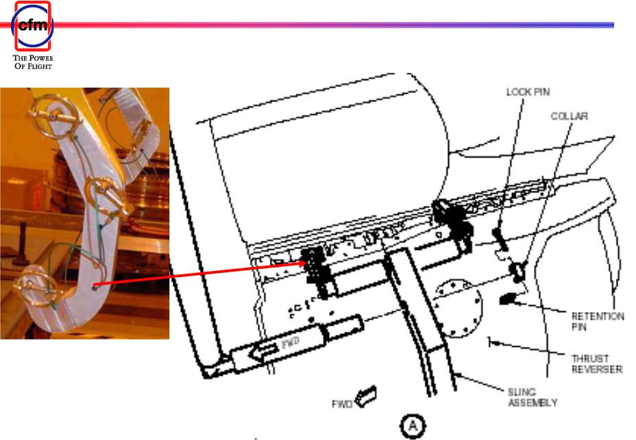
CFM56-7B
THRUST REVERSER TOOLING
Identification (1.A.a)
The C78018 tool.
After the thrust reverser segments have been reinstalled on the strut, they must be closed and locked.
As the segments are closed, seals located at the upper bifurcation of the segments are compressed providing resistance to the closure. To help overcome this resistance, a latching tool C78020 has been developed that attaches to the locking latch on the reverser segment and helps draw the segments together for locking.
EFFECTIVITY 737-600/700/800/900/BBJ/C40A/B/C/P8A/MMA/AWAC |
CFM PROPRIETARY INFORMATION |
TRAINING MANUAL
71-00-00 185
Sept. 2006
|
CFM56-7B |
TRAINING MANUAL |
|
||
|
|
|
THRUST REVERSER TOOLING
EFFECTIVITY 737-600/700/800/900/BBJ/C40A/B/C/P8A/MMA/AWAC |
|
CFM PROPRIETARY INFORMATION |
71-00-00 |
186 |
|
||||
|
|
|
Sept. 2006 |
|

|
CFM56-7B |
TRAINING MANUAL |
|
||
|
|
|
THRUST REVERSER TOOLING
Identification (1.A.a)
The C78018 tool.
EFFECTIVITY 737-600/700/800/900/BBJ/C40A/B/C/P8A/MMA/AWAC |
|
CFM PROPRIETARY INFORMATION |
71-00-00 |
187 |
|
||||
|
|
|
Sept. 2006 |
|
|
CFM56-7B |
TRAINING MANUAL |
|
||
|
|
|
THRUST REVERSER TOOLING
EFFECTIVITY 737-600/700/800/900/BBJ/C40A/B/C/P8A/MMA/AWAC |
|
CFM PROPRIETARY INFORMATION |
71-00-00 |
188 |
|
||||
|
|
|
Sept. 2006 |
|

|
CFM56-7B |
TRAINING MANUAL |
|
||
|
|
|
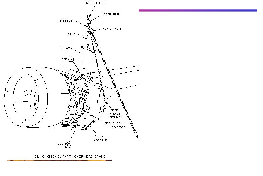
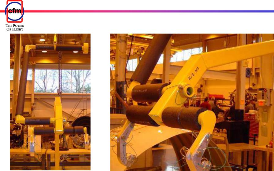
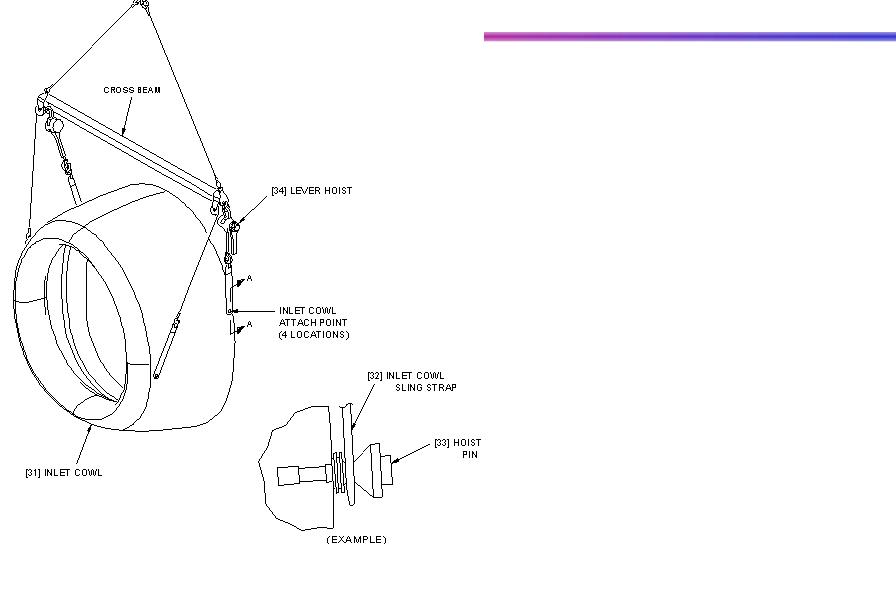
ENGINE INLET COWL TOOLING
Identification (1.A.a)
The inlet cowl may be installed/removed using a sling with an overhead hoist B71040 and dynamometer. Refer to the AMM TASK 71-11-01-000-801-F00 for removal of the inlet cowl. There is more than 1 tool to remove the inlet cowl.
Using this method of installation/removal requires caution to prevent damage to engine components,
accessories and fittings. The EEC cooling hose, TAI duct and T12 sensor must be removed.
The inlet cowl and ground handling points and the sling and how it attaches to the inlet cowl.
CAUTION: ADJUST THE SLING TO HOLD ONLY THE WEIGHT OF THE INLET COWL. MORE FORCE CAN
CAUSE DAMAGE TO THE INLET COWL. THE INLET
COWL WEIGHS 310 LBS.
EFFECTIVITY 737-600/700/800/900/BBJ/C40A/B/C/P8A/MMA/AWAC |
|
CFM PROPRIETARY INFORMATION |
71-00-00 |
189 |
|
||||
|
|
|
Sept. 2006 |
|
|
CFM56-7B |
TRAINING MANUAL |
|
||
|
|
|
ENGINE INLET COWL TOOLING
EFFECTIVITY 737-600/700/800/900/BBJ/C40A/B/C/P8A/MMA/AWAC |
|
CFM PROPRIETARY INFORMATION |
71-00-00 |
190 |
|
||||
|
|
|
Sept. 2006 |
|