

Introduction to 3D Game Programming with DirectX.9.0 - F. D. Luna
.pdf34 Part II
Chapter 7, “Blending”—In this chapter, we look at a technique called blending. This technique allows us to implement a number of special effects—in particular, glass-like transparency.
Chapter 8, “Stenciling”—This chapter describes the stencil buffer, which, like a stencil, allows us to block pixels from being drawn. To illustrate the ideas of this chapter, we include thorough discussions on implementing reflections and planar shadows using the stencil buffer.
|
|
Y |
|
L |
|
|
F |
|
|
M |
|
A |
|
|
E |
|
|
T |
|
|
Team-Fly®

Chapter 1
Direct3D Initialization
Initialization of Direct3D has historically been a tedious chore. Fortunately, version 8.0 adopted a simplified initialization model, and Direct3D 9.0 follows that same model. However, the initialization process still assumes that the programmer is familiar with basic graphics concepts and some fundamental Direct3D types. The first few sections of this chapter address these requirements. With these prerequisites met, the remainder of the chapter explains the initialization process.
Objectives
To learn how Direct3D interacts with graphics hardware
To understand the role that COM plays with Direct3D
To learn fundamental graphics concepts, such as how 2D images are stored, page flipping, and depth buffering
To learn how to initialize Direct3D
To become familiar with the general structure that the sample applications of this book employ
1.1Direct3D Overview
Direct3D is a low-level graphics API (application programming interface) that enables us to render 3D worlds using 3D hardware acceleration. Direct3D can be thought of as a mediator between the application and the graphics device (3D hardware). For example, to instruct the graphics device to clear the screen, the application would call the Direct3D method IDirect3DDevice9::Clear. Figure 1.1 shows the relationship between the application, Direct3D, and the hardware.
35

36 Chapter 1
Figure 1.1: The relationship between the application, Direct3D, and the hardware
The Direct3D part of Figure 1.1 is the defined set of interfaces and functions Direct3D exposes to the application/programmer. These interfaces and functions represent the entire features set that the current version of Direct3D supports. Note that just because Direct3D exposes a feature, it doesn’t imply that available graphics hardware supports it.
As Figure 1.1 shows, there is an intermediate step between Direct3D and the graphics device—the HAL (Hardware Abstraction Layer). Direct3D cannot interact directly with graphics devices because there are a variety of different cards on the market, and each card has different capabilities and ways of implementing things. For instance, two different graphics cards may implement the clear screen operation differently. Therefore, Direct3D requires device manufacturers to implement a HAL. The HAL is the set of device-specific code that instructs the device to perform an operation. In this way Direct3D avoids having to know the specific details of a device, and its specification can be made independent of hardware devices.
Device manufacturers implement all the features that their device supports into the HAL. Features exposed by Direct3D but not supported by the device are not implemented into the HAL. Calling a Direct3D function that is not implemented by the HAL results in failure, unless it’s a vertex processing operation, in which case the desired functionality can be emulated in software, if using software vertex processing, by the Direct3D runtime. Therefore, when using esoteric features that are only supported by a minority of devices on the market, be sure to verify that the device supports the feature (device capabilities are explained in section 1.3.8).
1.1.1 The REF Device
You may wish to write programs that use functionality that Direct3D exposes but are not implemented on your device. For this purpose, Direct3D provides a reference rasterizer (known as a REF device), which emulates the entire Direct3D API in software. This allows you to write and test code that uses Direct3D features that are not available on your device. For example, in Part IV of this book, we use vertex and pixel shaders, which many cards do not support. If your graphics card

Direct3D Initialization 37
does not support shaders, you can still test the sample code with the REF device. It is important to understand that the REF device is for development only. It ships only with the DirectX SDK and cannot be distributed to end users. In addition, the REF is slow enough that it’s not practical to use for anything but testing.
1.1.2 D3DDEVTYPE
In code, a HAL device is specified by D3DDEVTYPE_HAL, which is a member of the D3DDEVTYPE enumerated type. Similarly, a REF device is specified by D3DDEVTYPE_REF, which is also a member of the D3DDEVTYPE enumerated type. These types are important to remember because we will be asked to specify which type to use when creating our device.
1.2 COM
Component Object Model (COM) is the technology that allows DirectX to be language independent and have backward compatibility. We usually refer to a COM object as an interface, which for our purposes can be thought of and used as a C++ class. Most of the details of COM are transparent to us when programming DirectX with C++. The only thing that we must know is that we obtain pointers to COM interfaces through special functions or the methods of another COM interface; we do not create a COM interface with the C++ new keyword. In addition, when we are done with an interface, we call its Release method (all COM interfaces inherit functionality from the IUnknown COM interface, which provides the Release method) rather than delete it. COM objects perform their own memory management.
There is, of course, much more to COM, but more detail is not necessary for using DirectX effectively.
Note: COM interfaces are prefixed with a capital I. For example, the COM interface that represents a surface is called
IDirect3DSurface9.
1.3 Some Preliminaries
The initialization process of Direct3D requires us to be familiar with some basic graphics concepts and Direct3D types. We introduce these ideas and types in this section, making the next section that discusses Direct3D initialization more focused.
P a r t I I

38 Chapter 1
1.3.1 Surfaces
A surface is a matrix of pixels that Direct3D uses primarily to store 2D image data. Figure 1.2 identifies some components of a surface. Note that while we visualize the surface data as a matrix, the pixel data is actually stored in a linear array.
Figure 1.2: A surface
The width and height of a surface are measured in pixels. The pitch is measured in bytes. Furthermore, the pitch may be wider than the width, depending on the underlying hardware implementation, so you cannot assume that pitch = width · sizeof(pixelFormat).
In code, we describe surfaces with the IDirect3DSurface9 interface. This interface provides several methods for reading and writing data directly to a surface as well as a method to retrieve information about the surface. The most important methods of IDirect3DSurface9 are:
LockRect—This method allows us to obtain a pointer to the surface memory. Then, with some pointer arithmetic, we can read and write to each pixel in the surface.
UnlockRect—After you have called LockRect and are done accessing the surface’s memory, you must unlock the surface by calling this method.
GetDesc—This method retrieves a description of the surface by filling out a D3DSURFACE_DESC structure.
Locking a surface and writing to each pixel can be somewhat confusing at first, considering the surface pitch, so we have provided the following code block that locks a surface and colors each pixel red:

Direct3D Initialization 39
//Assume _surface is a pointer to an IDirect3DSurface9 interface.
//Assumes a 32-bit pixel format for each pixel.
//Get the surface description.
D3DSURFACE_DESC surfaceDesc; _surface->GetDesc(&surfaceDesc);
// Get a pointer to the surface pixel data. |
|
|
D3DLOCKED_RECT lockedRect; |
|
|
_surface->LockRect( |
|
|
&lockedRect,// pointer to receive locked data |
|
|
0, |
// lock entire surface |
|
0); |
// no lock flags specified |
|
// Iterate through each pixel in the surface and set it to red. |
|
|
DWORD* imageData = (DWORD*)lockedRect.pBits; |
|
|
for(int i = 0; i < surfaceDesc.Height; i++) |
|
|
{ |
|
II |
for(int j = 0; j < surfaceDesc.Width; j++) |
t |
|
{ |
|
r |
|
Pa |
|
|
// index into texture, note we use the pitch and divide by |
|
// four since the pitch is given in bytes and there are // 4 bytes per DWORD.
int index = i * lockedRect.Pitch / 4 + j;
imageData[index] = 0xffff0000; // red
}
}
_surface->UnlockRect();
The D3DLOCKED_RECT structure is defined as:
typedef struct _D3DLOCKED_RECT {
INT Pitch; // the surface pitch
void *pBits; // pointer to the start of the surface memory } D3DLOCKED_RECT;
Here are a few comments about the surface lock code. The 32-bit pixel format assumption is important since we cast the bits to DWORDs, which are 32-bits. This lets us treat every DWORD as representing a pixel.
Also, do not worry about understanding how 0xffff0000 represents red, as colors are covered in Chapter 4.
1.3.2 Multisampling
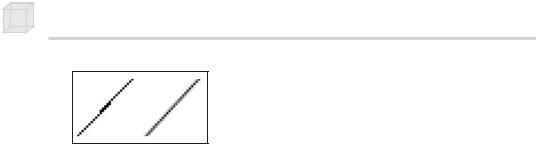
Multisampling is a technique used to smooth out blocky-looking images that can result when representing images as a matrix of pixels. One of the common uses of multisampling a surface is for full-screen antialiasing (see Figure 1.3).
40 Chapter 1
Figure 1.3: On the left we have a jagged line. On the right we have a sampled antialiased line, which is smoother.
The D3DMULTISAMPLE_TYPE enumerated type consists of values that allow us to specify the level of multisampling of a surface. They are:
D3DMULTISAMPLE_NONE—Specifies no multisampling
D3DMULTISAMPLE_1_SAMPLE… D3DMULTISAMPLE_16_ SAMPLE—Specifies multisampling levels from 1 to 16
There is also a quality level associated with the multisampling type. This is described as a DWORD.
In this book’s sample programs, we do not use multisampling because it slows down the application too much. If you wish to include it, remember to use the IDirect3D9::CheckDeviceMultiSampleType method to verify that your graphics device supports the multisampling type that you wish to use and check for valid quality levels.
1.3.3 Pixel Formats
We often need to specify the pixel format of Direct3D resources when we create a surface or texture. The format of a pixel is defined by specifying a member of the D3DFORMAT enumerated type. Some formats are:
D3DFMT_R8G8B8—Specifies a 24-bit pixel format where, starting from the leftmost bit, 8 bits are allocated for red, 8 bits are allocated for green, and 8 bits are allocated for blue
D3DFMT_X8R8G8B8—Specifies a 32-bit pixel format where, starting from the leftmost bit, 8 bits are not used, 8 bits are allocated for red, 8 bits are allocated for green, and 8 bits are allocated for blue
D3DFMT_A8R8G8B8—Specifies a 32-bit pixel format where, starting from the leftmost bit, 8 bits are allocated for alpha, 8 bits are allocated for red, 8 bits are allocated for green, and 8 bits are allocated for blue
D3DFMT_A16B16G16R16F—Specifies a 64-bit, floating-point pixel format. Starting from the leftmost bit, 16 bits are allocated for alpha, 16 bits are allocated for blue, 16 bits are allocated for green, and 16 bits are allocated for red.

Direct3D Initialization 41
D3DFMT_A32B32G32R32F—Specifies a 128-bit, floating-point pixel format. Starting from the leftmost bit, 32 bits are allocated for alpha, 32 bits are allocated for blue, 32 bits are allocated for green, and 32 bits are allocated for red.
For a complete list of supported pixel formats, look up D3DFORMAT in the SDK documentation.
Note: The first three formats (D3DFMT_R8G8B8, D3DFMT_X8R8G8B8, and D3DFMT_A8R8G8B8) are common and supported on most hardware. The floating-point pixel format and some of the other formats available (see the SDK docs) are not as widely supported. When using these not-so-widely supported formats, be sure to verify that your card supports a particular format before using it.
1.3.4 Memory Pools
Surfaces and other Direct3D resources can be placed in a variety of memory pools. The memory pool is specified by one of the members of the D3DPOOL enumerated type. The memory pools available are:
D3DPOOL_DEFAULT—The default memory pool instructs Direct3D to place the resource in the memory that is best suited for the resource type and its usage. This may be video memory, AGP memory, or system memory. Note that resources in the default pool must be destroyed (released) prior to an IDirect3DDevice9::Reset call, and must be reinitialized after the reset call.
D3DPOOL_MANAGED—Resources placed in the manage pool are managed by Direct3D (that is, they are moved to video or AGP memory as needed by the device automatically). In addition, a back-up copy of the resource is maintained in system memory. When resources are accessed and changed by the application, they work with the system copy. Then, Direct3D automatically updates them to video memory as needed.
D3DPOOL_SYSTEMMEM—Specifies that the resource be placed in system memory
D3DPOOL_SCRATCH—Specifies that the resource be placed in system memory. The difference between this pool and D3DPOOL_ SYSTEMMEM is that these resources must not follow the graphics device’s restrictions. Consequently, the device cannot access resources in this pool. But the resources can be copied to and from each other.
P a r t I I

42 Chapter 1
1.3.5 The Swap Chain and Page Flipping
Direct3D maintains a collection of surfaces, usually two or three, called a swap chain that is represented by the IDirect3DSwapChain9 interface. We do not go into the specifics of this interface since Direct3D manages it and we rarely need to manipulate it. Instead we will simply outline the purpose of it.
Swap chains and, more specifically, the technique of page flipping are used to provide smooth animation between frames. Figure 1.4 shows a swap chain graphically with two surfaces.
Figure 1.4: A swap chain with two surfaces: a front buffer and a back buffer
In Figure 1.4, the surface in the front buffer slot is the surface that corresponds to the image presently being displayed on the monitor. The monitor does not display the image represented by the front buffer instantaneously; it takes one-sixtieth of a second on a monitor with a refresh rate of 60 hertz, for instance. The application’s frame rate is often out of sync with the monitor’s refresh rate (for example, the application may be able to render frames faster than the monitor can display them). However, we do not want to update the contents of the front buffer with the next frame of animation until the monitor has finished drawing the current frame, but we do not want to halt our rendering while waiting for the monitor to finish displaying the contents of the front buffer either. Therefore, we render to an off-screen surface (back buffer); then when the monitor is done displaying the surface in the front buffer, we move it to the end of the swap chain and the next back buffer in the swap chain is promoted to be the front buffer. This process is called presenting. Figure 1.5 shows the swap chain before and after a presentation.

Direct3D Initialization 43
Figure 1.5: Presenting two times. When using a swap chain that contains two surfaces, we see that presenting basically amounts to swapping the surfaces.
Thus, the structure of our rendering code is:
1.Render to back buffer.
2.Present the back buffer.
3.Goto (1).
1.3.6Depth Buffers
The depth buffer is a surface that does not contain image data but rather depth information about a particular pixel. There is an entry in the depth buffer that corresponds to each pixel in the final rendered image. So if the rendered image had a resolution of 640x480, there would be 640x480 depth entries.
P a r t I I
Figure 1.6: A group of objects that partially obscure each other because one is in front of another
Figure 1.6 shows a simple scene where some objects partially obscure the objects behind them. In order for Direct3D to determine which pixels of an object are in front of another, it uses a technique called depth buffering or z-buffering.
Depth buffering works by computing a depth value for each pixel and performing a depth test. The depth test basically compares the depths of pixels competing to be written to a particular pixel location.